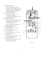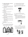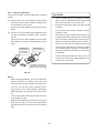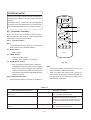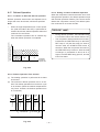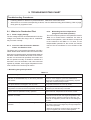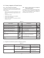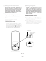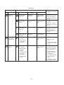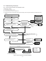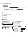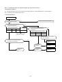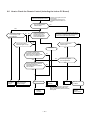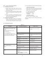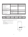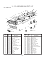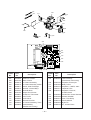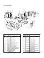
1
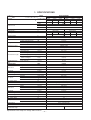
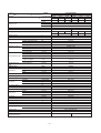
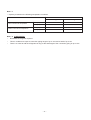
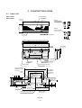
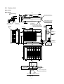
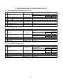
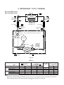
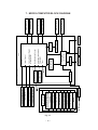
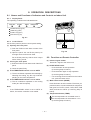
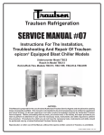
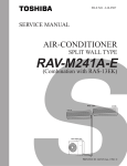
FILE NO. A10-9508
SERVICE MANUAL
AIR-CONDITIONER
SPLIT WALL TYPE
RAS-07EKH/RAS-07EAH
RAS-09EKH/RAS-09EAH
TOSHIBA
PRINTED IN JAPAN, Dec., 1995 S
CONTENTS
1. SPECIFICATIONS....................................................................................................... 3 ~ 5
2. CONSTRUCTION VIEWS ........................................................................................... 6 ~ 7
2-1.
2-2.
Indoor Unit ........................................................................................................................................ 6
Outdoor Unit ...................................................................................................................................... 7
3. CAUTION IN INSTALLATION.................................................................................... 8 ~ 12
3-1.
3-2.
3-3.
Installation of Indoor Unit .................................................................................................................. 8
Flaring ............................................................................................................................................. 10
Pipe Process Points ......................................................................................................................... 11
4. WIRING DIAGRAM ......................................................................................................... 13
5. SPECIFICATIONS OF ELECTRICAL PARTS ................................................................. 14
5-1.
5-2.
5-3.
RAS-07EKH/RAS-07EAH (Indoor Unit) .......................................................................................... 14
RAS-07EAH (Outdoor Unit) ............................................................................................................ 14
RAS-09EAH (Outdoor Unit) ............................................................................................................ 14
6. REFRIGERANT CYCLE DIAGRAM ............................................................................. 15
7. MICRO-COMPUTER BLOCK DIAGRAM ........................................................................ 16
8. OPERATION DESCRIPTIONS............................................................................... 17 ~ 31
8-1.
8-2.
8-3.
8-4.
8-5.
8-6.
8-7.
8-8.
8-9.
8-10.
8-11.
8-12.
8-13.
8-14.
8-15.
8-16.
8-17.
Names and Functions of Indicators and Controls on Indoor Unit .................................................... 17
Functions on Remote Controller ...................................................................................................... 17
Names and Functions of Indicators on Remote Controller .............................................................. 19
Handling the Remote Controller ...................................................................................................... 19
Automatic Operation ....................................................................................................................... 21
Heating/Cooling/Fan Only Operation .............................................................................................. 22
Dry Operation .................................................................................................................................. 23
Timer Operation .............................................................................................................................. 23
ADJUSTING AIR FLOW DIRECTION ............................................................................................. 25
FAN ONLY Operation ...................................................................................................................... 27
COOL Operation ............................................................................................................................. 27
HEAT Operation .............................................................................................................................. 28
ECONO. Mode ................................................................................................................................ 28
DRY Operation ................................................................................................................................ 29
AUTO Operation ............................................................................................................................. 29
Cool Airflow Prevention Control....................................................................................................... 30
Defrost Operation ............................................................................................................................ 31
9. TROUBLESHOOTING CHART ............................................................................... 32 ~ 44
9-1.
9-2.
9-3.
9-5.
9-6.
What to be Rechecked First ............................................................................................................
Primary Judgement of Trouble Sources ..........................................................................................
Troubleshooting Flowcharts ............................................................................................................
How to Check the Remote Control (Including the Indoor PC Board) ...............................................
PC Board Layout .............................................................................................................................
32
33
37
40
43
10. EXPLODED VIEWS AND PARTS LIST .............................................................. 45 ~ 47
10-1. Indoor Unit ...................................................................................................................................... 45
10-2. Outdoor unit .................................................................................................................................... 47
–2–
1. SPECIFICATIONS
Model
RAS-07EKH/EAH
Item
Capacity
220V
1.78
6070
kW
*1
Btu/h
Phase
V
Hz
W
%
A Indor/Outdoor
Power source
Power consumption
Power factor
Running current
Starting current
Moisture removal
Noise
Refrigerant
Indoor (H/M/L)
Outdoor (220/230/240V)
Name of refrigerant
Rated volume
A
lit/h
dB
dB
kg (oz)
Refrigerant control
Interconnection pipe
Condensale drain
pipe
INDOOR UNIT
Dimensions
Gas side size
Connection type
Liquid side size
Connection type
Maximum length (of one way)
Maximum height
Indoor unit higher
Outdoor unit higher
Outer diameter
Height
Width
Depth
Net weight
Evaporator type
Indoor fan type
Air volume
High fan
Medium fan
Low fan
Fan motor output
Air filter
OUTDOOR UNIT
Dimensions
Net weight
Condenser type
Outdoor fan type
Air flow volume
Fan motor output
Compressor
Safety device
Auto louver
Usable outdoor
temperature range
Height
Width
Depth
mm (in)
mm (in)
m (ft)
*2
240V
1.82
6210
220V
1.83
6240
Heating
230V
1.85
6310
240V
1.87
6380
Single
220/230/240
50
560/570/580
490/500/510
100/100/99
100/100/100
220V
230V
240V
220V
230V
240V
0.19/2.36 0.20/2.28 0.22/2.22 0.19/2.04 0.20/1.97 0.22/1.91
10
0.8
43/36/31
47/48/49
R22
0.65 (22.9)
Capillary tube
9.52 (3/8)
Flare connection
6.35 (1/4)
Flare connection
10 (32.8)
m (ft)
m (ft)
mm (in)
5 (16.4)
5 (16.4)
16 (5/8)
RASmm (in)
mm (in)
mm (in)
kg (lbs)
07EKH
265 (10.4)
790 (31.1)
155 (6.1)
8 (17.6)
Finned tube
Cross flow fan
462 (274)
370 (215)
300 (175)
m3/h (CFM)
m3/h (CFM)
m3/h (CFM)
W
RASmm (in)
mm (in)
mm (in)
kg (lbs)
m3/h (CFM)
W
Model
Output
Cooling
230V
1.80
6140
W
°C
Polypropylene net filter (Washable)
07EAH
530 (20.9)
770 (30.3)
200 (7.9)
29 (63.9)
Finned tube
Propeller
1500 (890)
18
PH70T1-4C
500
Fuse, Overload relay
Yes
21 – 43
Specifications are subject to change without notice.
–3–
–10 – 21
Model
RAS-09EKH/EAH
Item
Capacity
220V
2.28
7780
kW
*1
Btu/h
Phase
V
Hz
W
%
A Indor/Outdoor
Power source
Power consumption
Power factor
Running current
Starting current
Moisture removal
Noise
Refrigerant
Indoor (H/M/L)
Outdoor (220/230/240V)
Name of refrigerant
Rated volume
A
lit/h
dB
dB
kg (oz)
Refrigerant control
Interconnection pipe
Condensale drain
pipe
INDOOR UNIT
Dimensions
Gas side size
Connection type
mm (in)
Liquid side size
Connection type
Maximum length (of one way)
Maximum height
Indoor unit higher
Outdoor unit higher
Outer diameter
mm (in)
Height
Width
Depth
Net weight
Evaporator type
Indoor fan type
Air volume
High fan
Medium fan
Low fan
Fan motor output
Air filter
OUTDOOR UNIT
Dimensions
Net weight
Condenser type
Outdoor fan type
Air flow volume
Fan motor output
Compressor
Safety device
Auto louver
Usable outdoor
temperature range
Height
Width
Depth
m (ft)
240V
2.32
7920
220V
2.47
8430
Heating
230V
2.50
8530
240V
2.53
8630
Single
220/230/240
50
740/750/760
670/680/690
95/94/92
94/92/89
220V
230V
240V
220V
230V
240V
0.19/3.34 0.20/3.27 0.22/3.22 0.19/3.05 0.20/3.03 0.22/3.00
14
1.2
43/36/31
47/48/49
R22
0.67 (23.6)
Capillary tube
9.52 (3/8)
Flare connection
6.35 (1/4)
Flare connection
10 (32.8)
*2
m (ft)
m (ft)
mm (in)
5 (16.4)
5 (16.4)
16 (5/8)
RASmm (in)
mm (in)
mm (in)
kg (lbs)
09EKH
265 (10.4)
790 (31.1)
155 (6.1)
8 (17.6)
Finned tube
Cross flow fan
462 (274)
370 (215)
300 (175)
m3/h (CFM)
m3/h (CFM)
m3/h (CFM)
W
RASmm (in)
mm (in)
mm (in)
kg (lbs)
m3/h (CFM)
W
Model
Output
Cooling
230V
2.30
7850
W
°C
Polypropylene net filter (Washable)
09EAH
530 (20.9)
770 (30.3)
200 (7.9)
29 (63.9)
Finned tube
Propeller
1500 (890)
18
PH94T1-4C
750
Fuse, Overload relay
Yes
21 – 43
Specifications are subject to change without notice.
–4–
–10 – 21
Note: *1
• Capacity is based on the following temperature conditions.
JIS C9612-1994
Indoor unit inlet air temperature
Outdoor unit inlet air temperature
Cooling
Heating
(DB)
27°C
20°C
(WB)
19°C
–
(DB)
35°C
7°C
(WB)
24°C
6°C
Note: *2 CHARGELESS
•
No additional refrigerant required.
•
This air conditioner accepts a connection piping length of up to 10m and a head of up to 5m.
•
There is no need to add the refrigerant as long as the total length of the connection piping is up to 10m.
–5–
2. CONSTRUCTION VIEWS
2-1. Indoor Unit
RAS-07EKH
RAS-09EKH
Heal exchanger
Air filter
Air inlet
Wireless
remote controller
265
136
790
55
16
59.6
5
112.8
Remote
controller holder
Air outlet
Single phase 220-240V (50Hz)
790
222
Front panel
Hanger
346
155
222
392
Back body
Hanger
Drain hose
Connecting pipe (0.47m)
(0.53m)
(Flare ø6.35)
Connecting pipe (0.37m)
Terminal block
(Flare ø9.52)
659
450
For stud bolt
346
(ø8 ~ ø10)
For stud bolt
(ø6)
40 or more
Minimum distance
to ceiling
21
3
20
44
Detail of installing
dimensions of the
main unit
Hanger
Minimum
distance to wall
120 or more
289
Center line
Installation plate center line
790
Installation
plate outline
Fig. 2-1
–6–
106
40
106
2-ø65
Piping hole
30
Minimum
distance to wall
40
231
30
265
20
170 or more
2-2. Outdoor Unit
RAS-07EAH
RAS-09EAH
600
A Detail Drawing
A
85
111
36
Gas side (flare ø9.52)
ø25 Drain hole
600
50
216
230
216
30
230
R10
25
36
ø11x14 Hole
Liquid side (flare ø6.35)
50
ø6 Hole
8-ø6 Holes
(For fixing the outdoor unit)
4-ø11x14 Long holes
(For anchor bolt ø8-ø10)
111
Handle
5
11
11
Fan guard
200
ø420
TOSHIBA
Electric
parts cover
525
530
Z
268
54 62
5
89
Access for
charging
770
59
Z View
Inlet port
600 or more
Inlet port
100 or more
Visible outline (Minimum distance
of the product of the wall)
400 or more
230
45 or more
600
Outlet
port
4-ø11x14 Long holes
(For anchor bolt ø8-ø10)
Center
port
Mounting dimension of anchor bolt
Fig. 2-2
–7–
250
3. CAUTION IN INSTALLATION
3-1. Installation of Indoor Unit
3-1-1. Removing the Front Panel
(1) Open the screw caps and remove the two screws
securing the front panel.
(2) Close the screw caps as behind.
(3) Open the air outlet direction (up-down) louver horizontally by hand.
(4) Slightly open the lower part of the front panel,
then pull the upper part of the front panel toward
you to remove it from the rear plate.
Open it upward by
putting your finger
on the edge.
(4)
(4)
Fig. 3-1 Opening the screw cap
(1)(2) (3)
(1)(2)
Air outlet direction
louver.
Fig. 3-2 Removing the front panel
Caution When Connecting the Connecting Cable
When connecting the connective cable, follow the
instructions below.
Note:
•
(1) Remove the front panel.
Rear plate
Screws
Connect the indoor and outdoor units with a
connective cable over the shortest distance as
possible.
70mm
Rear plate
busing
Grounding wire
10mm
Screw
(4)
(3)
(2)
(1)
10mm
50mm
Wiring cover
Front panel
Cord clamp
Fig. 3-4
Fig. 3-3
–8–
(2) Insert the connective cable fully into the terminal block and secure it by screw tightly.
(5) Fix the wiring cover, rear plate bushing and front
panel on the indoor unit.
(3) Secure the connective cable with the cord clamp.
(4) Tightening torque should be 1.2 N.m (12 kgf.cm)
Connecting
cable
4
Wiring cover
1
2
3
Cord clamp
Screws
Grounding wire
Screw
Connecting cable
Fig. 3-6
Cord clamp
Fig. 3-5
3-1-2. Caution in Mounting the Front Panel
When the panel is removed and mounted again, follow the step described below.
3-1-3. Precautions for Refrigerant Piping
(1) Under-side connection with piping
(1) After fastening two screws, be sure to hook the
inside clicks (1) and (2) of the front panel shown
in Fig. 3-7, right gap is left between the front panel
and the rear plate.
Slit part
Pipe holder
Push
Push
(1)
(2)
Rear plate
Pipe holder
Fig. 3-8
Fig. 3-7
(1) Cut out the knockout piece from the right below
of the rear plate with a knife, etc. Smooth the cut
edge.
Note:
•
If cooling (dry) operation is made without pushing the air outlet, dew can be attached on the
front panel surface. In addition, a gap between
the front panel and the body will become wider,
spoiling the appearance.
(2) Set the drain hose in the inner part of the indoor
unit and connecting cable in lower part of it.
(3) Wind the tape round them.
Indoor unit
Piping
Connecting
cable
Wall
Drain hose
Installation plate
–9–
Fig. 3-9
3-2. Flaring
(2) Left-hand connection with piping
When the piping runs to the left, be sure to use a tool
such as a pipe bender to bend the pipe.
Note:
•
3-2-1. Pipe Cutting
(1) Cut the pipe little by little advancing the blade of
pipe cutter slowly.
If the pipe is bent incorrectly, the air conditioner
could be raised.
1/4 Thickness
Connection pipes
Fig. 3-12
Auxiliary
pipes
Note:
Fig. 3-10
(1) When the piping runs to the left, remove the left
side body bushing of the rear panel. You may
need the body bushing when you relocate the unit,
so be sure make the customer keep it in a safe
place.
•
For fine work, do not advance the blade by force
in order to prevent distortion of the pipe, and extra burrs.
•
Cut the pipe a little longer than required.
(2) After passing the connection pipe through the pipe
hole, connect the connection pipe to the auxiliary
pipes and wrap covering tape around them.
(3) For left-hand connection with piping, bend the
pipes as shown in Fig. 3-11.
Connection pipes
120mm
3-2-2. Burr Removal
(1) Raise burrs with the burr stick or the burr remover.
(Hold the flaring end down to prevent burrs from
dropping inside pipe)
43 mm
Indoor unit external shape
Fig. 3-13
Wall
Fig. 3-11
Note:
•
Bend the connection pipe so that the distance
between the pipe and the wall be 43 mm or less.
Fig. 3-14
– 10 –
Note:
•
Be sure to remove burrs to avoid unevenness on
the flare face which will cause gas leaks.
•
•
Fine flaring work shows even brightness on the
flared surface and uniform thickness of pipe.
•
Unsuccessful flaring work causes gas leaks,
therefore rework it.
Cover the pipe end with a polyethylene bag and
on sheet.
Slant
Scratch
Crack
Uneven
thickness
Fig. 3-17
•
The above faulty flaring will cause gas leaks.
Fig. 3-15
3-2-3. Point of Flaring
(1) The exact length of pipe protruding from the face
of the flare die is determined by the flaring, too.
3-2-4. Finishing Work
(1) Fix the pipe firmly on the flare die. Match the centers of both the flare die and the flaring punch,
and tighten flaring punch fully.
D
A
3-3. Pipe Process Points
3-3-1. Pipe Bending
(1) Carefully bend by hand.
Note:
Fig. 3-16
•
Collapsed pipe cause cooling failure.
Note:
•
Too long a protrusion of pipe from the flaring tool
will result in too long a flare; If this happens, the
flare nut will not tighten and the joint will not seat.
•
Too small a protrusion will cause gas leaks.
CAUTION:
•
•
Too large protrusion of pipe results in impossible tightening of the flare nut.
Fig. 3-18
•
Too small a protrusion of pipe will cause gas
leaks due to insufficient flare surface.
(2) Bend with pipe bender. (Since the insulation is
wound on, use the bender by sliding the insulation to one side, or cutting it halfway.)
Table 3-1 shows the use of an imperial die and a
rigid die.
Table 3-1
Type of pipe
A (mm)
D (mm)
Imperial
Rigid
1/4”
6.35
1.3
0.7
3/8”
9.52
1.6
1.0
Fig. 3-19
– 11 –
(3) The radius of the pipe bend should be 100 mm or
more.
Note:
•
Insufficient tightening causes gas leaks. Over
tightening results in cracks the flared surface.
R
100mm
CAUTION:
Fig. 3-20
(4) Too small a radius causes collapse of pipe.
10
•
Do not use the spanner from the beginning of
tightening.
•
When processing 1/4 inch pipe, tighten lightly
with spanner and then tighten additionally by
90 – 120 degree with torque wrench and spanner.
7
Table 3-2 Tightening torque of flare nut
Pipe size
Standard
torque
The distortion ratio
must be less than 10:7.
6.35 mm (1.4")
9.52 mm (3/8")
15.7 (160)
29.4 (300)
(Unit: N.m (kgf.cm))
Fig. 3-21
3-3-2. Pipe Connection
(1) Connect the flare pipe close to the air conditioner
unit so both faces fit well.
Note:
•
Forcing to tighten the nut without the center axis
coincided causes gas leaks.
Fig. 3-24
Match centers
Flare nut
Fig. 3-22
Fig. 3-25
(2) Use a torque wrench and spanner to tighten or
untighten the flare nut. Tightening should be done
by finger first, then use the torque wrench. A
torque wrench helps to provide adequate torque
for tightening.
Fig. 3-23
– 12 –
4. WIRING DIAGRAM
RAS-07EKH/RAS-07EAH
RAS-09EKH/RAS-09EAH
LOUVER
MOTOR
1o 50Hz
220/230/240V~
INDICATION&SWITCH
PARTS
THERMAL
FUSE 77 C
(FAN MOTOR)
RY08
COMMON
GROUND RELAY
TERMINAL
3
4
CN12
IC03
3 RY07
POWER
4 RELAY
T3.15A
250V
R900
TNR
C51
IC
C60
3 3
BLK
1 1
RED
RUNNING
CAPACITOR
1 1
CN01
2 2
PTH
TH01
IC05
CN29
CN17
1 2 3
1 2 3
4
4
RED
WHI
BLK
1
1
CN06
1 2 3
1 2 3
1
1
PJ18 1 2 3
1 2 3
GRN
&YEL
BLU
1 2 3
CN03
RED
IC04
GRY
ZC
BLU
ZC
1
1
CN05
3
3
3
CN32
3
INFRARED RAY
RECEIVE PARTS
4
TRANSFORMER
3 2 1
CN33
3 2 1
INDOOR
OUTDOOR
OVER LOAD
RELAY
1 2 3 4
GRN&YEL
BLK
BLK
RUNNING
CAPACITOR
RED
RUNNING
CAPACITOR
COLOR IDENTIFICATION
BRW
RED
WHI
YEL
BLU
BLK
GRY
PNK
ORN
GRN&YEL
BLK
SOLENOID COIL
BLK
CHASSIS
WHI
RED
BLK
COMPRESSOR
Fig. 4-1
– 13 –
1 1
2 2
WHI
C.T.
T01
RED
WHI
THERMAL
PROTECTER
(90 C)
YEL
1 1
CN13 2 2 GRY
3 3 BRW
CN10
WHI
5 5
F01 FUSE
BLK
WHI
RED
GRN&YEL
GRN
&YEL
6 5 4 3 2 1
6 5 4 3 2 1
CN31
1 2 3
1 2 3
1 2 3 4 5 6 7 8
CN24
R901 TNR
SG01 DSA
P04
FAN MOTOR
BLU
PNK
YEL
ORN
RED
BRW
WHI
GRY
1 2 3 4 5 6 7 8
CN25 1 2 3 4 5 6 7 8
GRY
BRW
BLU
GRN&YEL
:
:
:
:
:
:
:
:
:
:
BROWN
RED
WHITE
YELLOW
BLUE
BLACK
GRAY
PINK
ORANGE
GREEN &
YELLOW
HEAT
EXCHANGER
SENSOR
(TC)
THERMO.
SENSOR
(TA)
5. SPECIFICATIONS OF ELECTRICAL PARTS
5-1. RAS-07EKH, RAS-09EKH (Indoor Unit)
No.
1
Fan motor (For indoor)
MMF-200-18-2C
2
3
Thermo sensor (TA sensor)
Runing
for indoor fan motor
capacitor
Transformer
Microcomputer
Power relay, Common relay
Heat exchanger sensor
(TC-sensor)
(microporcessor)
Specifications
Output (Rated) 18W, 2 pole, 1 phase, 220 – 240V, 50 Hz
White-Black
Winding resistance (Ω)
Red-Black
(at 20°C)
209.4
101.6
Adjustable range: 17 – 30°C
EVN40M105UL1
400WV, 1µF
TTZ-200/240-1
TMP87CH40N
G4A-1A
(microprocessor)
Primary 200 – 240V, Secondary 15V
4
5
6
7
Parts name
Type
Coil: 12V 90mA, Rated 250V 20A
10 KΩ at 25 °C
5-2. RAS-07EAH (Outdoor Unit)
Parts name
No.
1
Type
Compressor
PH70T1-4C
Fan motor (For outdoor)
UE6-21A5P
2
3
4
5
6
Running capacitor (For fan motor)
Running capacitor (For compressor)
Solenoid coil
Overload relay
EEP2G155HQA104
SK-40CMF15UT
LB60012
J-MRA99259-9201
Specifications
Output (Rated) 500W, 2 pole, 1 phase, 220 – 240V, 50 Hz
White-Black
Winding resistance (Ω)
Red-Black
(at 20°C)
6.55
4.46
Output (Rated) 18W, 6 pole, 1 phase, 220 – 240V, 50 Hz
Red-Black
White-Black
Winding resistance (Ω)
(at 20°C)
366.2
368.5
400V AC, 1.5µF
400VAC, 15µF
AC: 200/240V
AC: 200/240V
5-3. RAS-09EAH (Outdoor Unit)
No.
1
Parts name
Type
Compressor
PH940T1-4C
Fan motor (For outdoor)
UE6-21A5P
2
3
4
5
6
Running capacitor (For fan motor)
Running capacitor (For compressor)
Solenoid coil
Overload relay
EEP2G155HQA104
EAG40M206UF2
LB60012
J-MRA99260-9200
Specifications
Output (Rated) 750W, 2 pole, 1 phase, 220 – 240V, 50 Hz
White-Black
Winding resistance (Ω)
Red-Black
(at 20°C)
8.73
4.53
Output (Rated) 18W, 6 pole, 1 phase, 220 – 240V, 50 Hz
Winding resistance (Ω)
Red-Black
White-Black
(at 20°C)
366.2
368.5
400V AC, 1.5µF
400V AC, 15µF
AC: 200/240V
AC: 200/240V
– 14 –
6. REFRIGERANT CYCLE DIAGRAM
RAS-07EKH/RAS-07EAH
RAS-09EKH/RAS-09EAH
Indoor unit
Evaporator
TI
Cooling
0.37m
(Connecting pipe)
/ 9.52
Heating
0.47m
(Connecting pipe)
/ 6.35
Cross flow fan
O.D. : 9.52mm
Optional piping kits
RB-P31BEF1 (3m)
RB-P51BEF1 (5m)
RB-P71BEF1 (7m)
P
O.D.:6.35mm
Packed valve
( / 9.52)
Cooling
PH70T1-4C(RAS-07EAH) (Rated volume 0.65 kg)
Heating
4-way valve
Heating Cooling
Packed valve
( / 6.35)
PH94T1-4C(RAS-09EAH) (Rated volume 0.67 kg)
Compressor
Accumulator
Dryer
Condenser
Capillary tube
RAS-07EAH
/1.5x1700
RAS-09EAH
/1.5x1500
Propeller fan
Cooling
Heating
Outdoor unit
Mark(
)means check points of Gas Leak
Fig. 6-1
Table 6-1
Standard pressure
P (kg/cm2G)
Cooling Heating
50Hz
Model
Standard
High temperature
Low temperature
Standard
High temperature
Low temperature
RAS-07EKH
12.6
17.1 ~ 19.9
10.4
6.5
6.2
4.6
RAS-09EKH
14.2
19.8 ~ 22.8
11.9
6.2
6.9
4.5
Surface temp. of heat
exchanger
interchanging pipe T 1 (°C)
RAS-07EKH
34.5
45.5 ~ 52.0
29.5
12.5
18.5
3.0
RAS-09EKH
38.5
52.0 ~ 59.0
34.1
11.4
14.6
2.4
Fan speed
(indoor)
High
Low
High
High
High
Low
Ambient temp.
conditions DB/WB
(°C)
Indoor
20/–
27/–
20/–
27/19
32/23
21/15
Outdoor
7/6
21/15
–10/–10
35/24
43/26
21/15
Note:
• Measure the heat exchanger temperature at the center of U-bend (By means of thermistor thermometer.)
During heating overload, the high temperature limit control operation is included.
– 15 –
Infraed
Rays
Fig. 7-1
– 16 –
1/ 50Hz
AC 220/230/240V
ECONO.
Transformer
Louver Direction Setting
Louver AUTO Swing
OFF TIMER Setting
ON TIMER Setting
Fan Speed Selection
Thermo Setting
Operation Mode Selection
AUTO,COOL,DRY,HEAT
FAN ONLY
Operation
(START/STOP)
Power Source
Compressor
Power Relay
4-Way Valve
Power Photocoupler
Louver Motor
Relay Driver
Louver Driver
Compressor
ON/OFF Signal
Phase Output
Processing (Temperature
Processing)
Clock Frequency
Oscillator Circuit
50Hz input
DC5V
Timer
Motor Revolution Control
Initializing Circuit
3-minute Delay at Restart
for Compressor
Current Sensor
Infrared Signal Receiver
Louver Control
Functions
C.P.U.
Termo. Sensor
Heat Exchanger Sensor
Main Unit Control Panel
Outdoor Fan Motor
Indoor Fan Motor
PRE-DEF.Sign Display
ECONO Sign Display
Timer Display
Operation Display
7. MICRO-COMPUTER BLOCK DIAGRAM
8. OPERATION DESCRIPTIONS
8-1. Names and Functions of Indicators and Controls on Indoor Unit
8-1-1. Display Panel
The operating conditions are indicated below.
PRE.-DEF
ECONO.
TIMER
OPERATION
OPERATION lamp (green)
TIMER lamp (yellow)
ECONO. lamp (green)
PRE.-DEF lamp (red)
Fig. 8-1
TEMPORARY
8-1-2. Control Panel
AUTO
Lift the front panel to perform control panel setting.
TEST RUN
(COOL)
(1) Opening the front panel
1) Push the PUSH on both lower corners of the
front panel.
Fig. 8-2
2) Open the panel. You can lift the panel up to
an angle where it will remain fixed.
Do not lift the panel any further when it stops
with a clicking sound.
(2) Closing the front panel
1) Push the PUSH on both lower ends of the front
panel.
8-2. Functions on Remote Controller
(a) Infrared signal emitter
Transmits a signal to the indoor unit.
(b) START/STOP button
2) Close the panel firmly.
•
Push the button to start operation.
(A receiving beep is heard.)
•
Push the button again to stop operation.
(A receiving beep is heard.)
•
If no receiving sound is heard from the indoor
unit, push the button twice.
(3) If the TEMPORARY switch is set to AUTO
1) The air conditioner operates automatically by
selecting the cooling, dry, fan only mode depending on the room temperature.
(4) If the TEMPORARY switch is set to COOL
1) The air conditioner operates in the cooling
mode (at a low fan speed).
(c) Mode select button (MODE)
Push this button to select modes. Each time you
push the button, a mode is selected in a sequence
that goes from AUTO, COOL, DRY, HEAT, FAN
ONLY, and back to AUTO. (A receiving beep is
heard).
Note:
•
REMOTE CONTROL
If the TEMPORARY switch is set to AUTO or
COOL, the remote controller is not usable.
(d) Temperature button (TEMP.)
The set temperature is increased to 30°C.
The set temperature is decreased to 17°C.
(A receiving beep is heard.)
– 17 –
(e) Fan speed button (FAN)
(a)
•
Push this button to select fan speed.
•
When you select AUTO, the fan speed is automatically adjusted according to the room
temperature. You can also manually select the
desired fan speed from three settings.
(A receiving beep is heard.)
•
Push this button to swing the louver.
(A receiving beep is heard.)
•
(i)
(d)
START/STOP
To adjust the air flow direction by the wireless
REMOTE CONTROLLER during the air conditioner operation, push this button.
(A receiving beep is heard.)
While this button is kept depressed, the receiving tone continuously sounds.
(j)
(b)
ECONO.
(e)
AUTO
SET
(f)
(g)
Push this button to set the OFF timer.
MODE
TIMER
(k)
(i)
Push this button to reserve timer settings.
(A receiving beep is heard.)
ON
OFF RSV
(h)
(l)
Push this button to cancel on timer and off
timer. (A receiving beep is heard.)
TOSHIBA
Economy button (ECONO.)
•
Push this button to set the economical operation mode of the air conditioner.
(A receiving beep is heard.)
Fig. 8-3
– 18 –
CNL
(j)
(k) Cancel button (CNL)
•
(c)
Push this button to set the ON timer.
Reserve button (RSV)
•
FAN
(l)
On timer button (ON)
•
HIGH
Push this button again to stop louver swinging. (A receiving beep is heard.)
(h) Off timer button (OFF)
•
AUTO
LOW
MED.
TEMP.
(g) Set louver button (SET)
•
FAN
AUTO
COOL
DRY
HEAT
FANONLY
(f) Auto louver button (AUTO)
•
TEMP.
MODE
8-3. Names and Functions of Indicators
on Remote Controller
8-4. Handling the Remote Controller
(a) Transmission indicator
Keep the remote controller where its signals can reach
the receiver of the air conditioner (a distance of 7m is
allowed.)
•
8-4-1. Location of the Remote Controller
This transmission indicator lights when remote
controller transmits signals to the indoor unit.
(b) ON/OFF display
•
Displayed by pushing the START/STOP button.
•
Push the START/STOP button again to disappear.
7m
(c) MODE display
•
Displays the current operation mode.
(d) TEMP. display
•
•
Fig. 8-5
Displays the temperature setting
(17°C to 30°C)
8-4-2. Remote Controller Mounting Fixture
When you set the operating mode to FAN
ONLY, no temperature setting is displayed.
A mounting fixture for the remote controller is supplied with it.
(1) Installing the mounting fixture
(e) ECONO. display
•
Displayed by pushing the ECONO. button.
•
Push the ECONO. button again to disappear.
Before you actually install the mounting fixture
on a wall or the pillar, check whether the remote
control unit signals from the location where you
will install the fixture can be received by the indoor unit.
(r) FAN speed display
•
Displays the selected fan speed. AUTO and
three fan speed levels “LOW”, “MED”, “HIGH”
can be indicated.
•
Displays AUTO when the operating mode is
either AUTO or DRY.
(g) TIMER display
The time set for timer operation is indicated.
Note:
•
In Fig. 8-4, all displays are indicated for the sake
of clarity. During operation, only the relevant displays will be shown on the remote controller.
Fig. 8-6
(2) Mounting and removing the remote controller
(c)
(e) (a)
MODE
(d)
TEMP.
AUTO
COOL
DRY
HEAT
FANONLY
(b)
(f)
To mount, hold the remote controller parallel to
the mounting fixture and push it in fully. To remove, slide the remote controller upwards and
out from the mounting fixture.
FAN
AUTO
LOW
MED.
Hr.ON OFF TIMER HIGH
(g)
Fig. 8-4
– 19 –
Fig. 8-7
8-4-3. Replacing Batteries
The remote controller uses two alkaline dry batteries
(LR03).
(1) Remove the cover of the battery compartment at
the back of the remote controller by sliding it out
in the direction of the arrow.
CAUTIONS:
•
The air conditioner will not operate if curtains
doors or other materials block the signal from
the remote controller to the indoor unit.
•
Prevent any liquid from failing into the remote
controller.
Remove the used batteries and insert new batteries.
(2) Press a coin or the similar object against the unit
to reset, and perform resetting. Then, close the
rear lid.
(Once the cell has been replaced, the controller
may malfunction. Perform resetting (ACL) accordingly.)
Be careful not
to reverse the
+ position and
the - position.
Do not expose the remote controller to direct
sunlight or heat.
•
If the infrared signal receiver at the indoor unit
is exposed to direct sunlight, the air conditioner
may not function properly. Use curtains to prevent the sunlight from falling on the receiver.
•
If the room using the air conditioner has fluorescent lighting with electronic starters, signals
may not be properly received. If you are planning to use such florescent lamps, consult your
local dealer.
•
If other electrical appliances react to the remote control, either move these appliances or
consult your local dealer.
Press a coin or
the similar object.
If the display should turn
out abnormal, the normal
display may be restored.
Fig. 8-8
Notes:
•
When replacing batteries, do not use used batteries or batteries of a different type. Such use
may cause the remote controller to malfunction.
•
If you do not use the remote controller over a
long period, remove the batteries. Otherwise,
battery leakage may damage the remote controller.
•
The average battery life during normal use is approximately one year.
•
Replace the batteries when there is no receiving
beep from the indoor unit or if the transmission
indication lamp on the remote control unit fails to
light.
– 20 –
OPERATING MODE:
Once you select the operating mode, the operating
conditions are saved in the unit’s microcomputer
memory.
MODE
TEMP.
FAN
AUTO
Thereafter, the air conditioner will start operating
under the same conditions when you simply push
the START/STOP button of the remote controller.
AUTO
TEMP.
(2)
START/STOP
(3)
8-5. Automatic Operation
When you set the air conditioner in AUTO mode, it
will automatically select cooling, or fan only operation
depending on the room temperature.
ECONO.
FAN
AUTO
SET
8-5-1. Operation Steps
•
(1)
MODE
Start
TIMER
The OPERATION lamp (green) on the display
panel of the indoor unit starts flashing.
ON
OFF RSV
CNL
(1) Mode button
•
Select AUTO.
TOSHIBA
(2) TEMP. button
•
Push the TEMP. button.
•
Normally, set it between 21°C to 28°C.
(3) START/STOP button
Fig. 8-9
•
Push this button to start the air conditioner.
•
The OPERATION lamp (green) on the display
panel of the indoor unit lights. The operating
mode is selected in accordance with the room
temperature and operation starts after approximately 3 minutes.
Note:
•
If the AUTO mode is uncomfortable, you can select the desired conditions manually.
•
When you select the AUTO mode, you do not
have to set the fan speed. The FAN speed display will show AUTO and the fan speed will be
automatically controlled.
Stop: START/STOP button
•
Push this button again to stop the air conditioner.
Table 8-1
Room temperature of operation
Operating conditions
The set temperature +1°C or higher
(when hot)
Cooling operation
Performs the cooling operation at a temperature 1°C higher than the setting.
The set temperature –1°C to +1°C
Fan only operation
Performs the fan only oepration (low speed)
while monitoring the room temperature.
When the room temperature changes, the air
conditioner will select the cooling or heating
mode.
The set temperature –1°C or lower (when
cool)
Heating operation
Performs the heating operation at a temperature 1°C lower than the setting.
– 21 –
8-6. Heating/Cooling/Fan Only Operation
8-6-1. Operation Steps
MODE
Start
COOL
•
TEMP.
FAN
AUTO
The OPERATION lamp (green) on the display
panel of the indoor unit starts flashing.
TEMP.
(1) Mode button
•
(2)
START/STOP
Select HEAT, COOL or FAN ONLY.
(4)
(2) TEMP. button
•
Push the TEMP. button.
•
Cooling 21°C or higher.
ECONO.
FAN
AUTO
SET
(3)
(3) FAN button
•
Select any of the “AUTO”, “LOW”, “MED” and
“HIGH”.
TIMER
(4) START/STOP button
•
Push this button again to stop the air conditioner.
•
The OPERATION lamp (green) on the display
panel of the indoor unit lights. The operating
mode is selected in accordance with the room
temperature and operation starts after approximately 3 minutes. (If you select FAN ONLY
mode, the unit will start immediately.)
ON
OFF RSV
CNL
TOSHIBA
Fig. 8-10
Stop: START/STOP button
•
(1)
MODE
Push this button again to stop the air conditioner.
Note:
•
– 22 –
The FAN ONLY mode does not control temperature. Therefore, perform only steps (1), (3) and
(4) to select this mode.
8-7. Dry Operation
8-8. Timer Operation
8-7-1. Operation Steps
8-8-1. Operation Steps
Start
The timer-reserved time indicates the time remaining
available. The time indicated on the remote controller
changes accordingly.
•
The OPERATION lamp (green) on the display
panel of the indoor unit starts flashing.
(1) ON or OFF TIMER button
(1) Mode button
•
Select DRY.
•
Push the ON or OFF TIMER buttons as required.
•
Each time the button is pressed, the timer
setting changes and set time flashes.
•
The indication changes as follows:
0.5 → 1.0 → 1.5 → 2.0 → 3.0 → ... → 23 →
24 Hr.
(2) TEMP. button
•
Push the TEMP. button.
•
The fan speed indicator displays AUTO.
•
The indoor fan speed will be automatically selected low.
(4) START/STOP button
(2) Reserve button (RSV)
•
Push this button again to stop the air conditioner.
•
The OPERATION lamp (green) on the display
panel of the indoor unit lights, and operation
starts after approximately 3 minutes.
•
Push this button. Check that the TIMER lamp
(yellow) on the display panel of the indoor unit
is lit.
•
Push the button once more and you will be
able to confirm the available remaining time
in the timer.
Stop: START/STOP button
•
Push this button again to stop the air conditioner.
(3) Cancel button (CNL)
•
MODE
TEMP.
Push the CNL button to cancel the timer setting.
FAN
AUTO
MODE
DRY
TEMP.
FAN
AUTO
AUTO
LOW
MED.
TEMP.
Hr.ON
HIGH
(2)
TEMP.
(3)
START/STOP
START/STOP
ECONO.
FAN
AUTO
SET
(2)
(3)
ECONO.
FAN
AUTO
SET
(1)
MODE
TIMER
MODE
TIMER
ON
OFF RSV
CNL
(1)
(3)
ON
OFF RSV
TOSHIBA
TOSHIBA
Fig. 8-11
Fig. 8-12
– 23 –
CNL
(2)
(2) ON TIMER (Stop ∅ Operation)
CAUTION:
The ON TIMER feature is useful when you wake
up in the morning or when you return home. The
air conditioner will automatically start operating
at the time set.
When you select the timer operation, the remote
controller automatically transmits the timer signal
to the indoor unit at the specified time. Therefore,
keep the remote controller in a location from which
it can transmit the signal to the indoor unit properly.
Example:
To turn on the air conditioner 5 hours later.
1) Continue pushing the “ON” TIMER button until you get “5.0”.
Changing
2) Push the RSV button.
•
Push the ON or OFF TIMER button once.
•
The indication of set time will start flashing.
•
Perform steps (1) and (2) to change the setting.
Hr.
Operation
8-8-2. Example of Timer Setting
(1) OFF TIMER (Operation → Stop)
Stop
The OFF TIMER feature is useful when you go
to sleep. The air conditioner will stop automatically at the time set.
5.0 hr.
Example:
To turn off the air conditioner 7 hours later.
Fig. 8-14
1) Continue pushing the “OFF” TIMER button
until you get “7.0”.
2) Push the RSV button.
Hr. OFF
ON TIMER
TIMER
Stop
Operation
7.0 hr
Fig. 8-13
– 24 –
8-9. ADJUSTING AIR FLOW DIRECTION
(4) During cool and dry operation, change the air flow
direction within the range indicated.
8-9-1. Adjustment of Vertical Air Flow Direction
(1) When using the wireless auto louver, the air flow
direction is automatically set to the desired position of the last time adjusted during operation.
When the cooling
or dry operation,
set the louver in
the blue zone.
The air flow direction
is automatically set to
the desired position of
the last time adjusted.
Louver indicator
Fig. 8-15
(2) When you stop operation using the remote controller, the louver is closed.
Fig. 8-17
Note:
•
In the Cool or Dry operation, remember not to
continue the downward air flowing for a long time
to avoid conceivable dewing on the louver surface and resultant dripping trouble.
•
It is also possible to adjust the air flow direction
by the remote controller even when the wireless
auto louver is in use, but once the air conditioner
operation was stopped and restarted thereafter,
the air flowing direction automatically becomes
horizontal.
•
The air flow cannot be adjusted with the remote
controller when the air conditioner is stopped.
(Also when the ON TIMER is indicated on the
display.)
Fig. 8-16
(3) When setting the air flow direction to your preference, hold down the SET LOUVER button of the
remote controller and set the air flow in the direction you desire.
– 25 –
8-9-2. Adjusting the Horizontal Air Flow
Direction
Preparation:
For the cooling or dry operation, move the vertical air
flow louver downward using the SET button on the
remote controller.
(1) Take hold of the lever on the horizontal air flow
grilles and move them to adjust the air flow direction as required.
Fig. 8-20
CAUTIONS:
Lever
•
The SET and AUTO buttons will be disabled
when the air conditioner is not in operation (including when the ON TIMER is set).
•
Do not operate the air conditioner for long hours
with the air flow direction set downward during
the cooling or dry operation. Otherwise, condensation may occur on the surface of the vertical louver and cause dew dripping.
•
Do not move the vertical louver manually. Always use the SET button. If you move the louver manually, it may malfunction during operation. If the louver malfunctions, stop the air conditioner once, and restart.
•
When the air conditioner is started immediately
after it was stopped, the vertical louver might
not move for 10 seconds or so.
•
The angle of the two vertical louvers may differ when they move downward and upward.
Fig. 8-18
(2) You can adjust the air flow at the left, right locations of the grilles.
(3) For the cooling or dry operation, return the vertical air flow louver to the original position using
the SET button on the remote controller.
Fig. 8-19
8-9-3. Adjusting the Automatic Swing Air Flow
Direction
Perform this function while the air conditioner is in
operation.
(1) Push the AUTO button on the remote controller.
(2) To stop the function, push the AUTO button again.
(3) To change the swing direction, push the SET button.
– 26 –
Table 8-2 Manual setting of FAN SPEED
PREPARATION:
•
•
•
Indication of FAN SPEED
Air volume
LOW
LOW
MED
MED
HIGH
HIGH
When the power plug (or cord) is connected to
EKH: AC 220/230/240V (50 Hz) outlet, the OPERATION (ON) lamp starts flashing, indicating that power has been turned on (or that
power failure occurred).
Confirm that the remote control TEMPORARY
switch is set to the REMOTE CONTROL position.
8-11. COOL Operation
(The remote controller’s MODE button is set to the
COOL position)
When the remote controller’s START/STOP
button is pushed, a receive tone is heard from
the main unit and the following operations are
carried out.
(1) Once the setting is made, the operation mode is
memorized in the microcomputer so that the same
operation can be effected thereafter simply by
pushing the START/STOP button.
8-10. FAN ONLY Operation
(The remote controller’s MODE button is set to the
FAN ONLY position.)
(1) Once the setting is made, the operation mode is
memorized in the microcomputer so that the same
operation can be effected thereafter simply by
pushing the START/STOP button.
(2) Relay RY07, RY08 is turned on to energize the
outdoor unit, and a cool operation is carried out.
The indoor fan motor operates as shown in Fig.
8-22 when FAN SPEED button is set to AUTO.
The motor operates with a constant air volume
as listed in Table 8-2, when the FAN SPEED button is set to LOW, MED, or HIGH.
(Room temp. - Set temp.)
(2) When the FAN SPEED button is set to the AUTO
position, the indoor fan motor operates as shown
in Fig. 8-21. When the FAN SPEED button is set
to LOW, MED, or HIGH, the motor operates with
a constant air volume as listed in Table 8-2. Power
relay RY7 is turned off.
(Room temp.)
Set
temp.
27
HIGH
HIGH
+4
MED
+3
LOW (+)
+2
LOW
+1
LOW
(continuous)
0
RY07 OFF
Set
temp.
HIGT
Fig. 8-22 AUTO
HIGT
26
MED
25
LOW (+)
24
LOW
23
LOW
Fig. 8-21 Auto setting of air volume
8-11-1. Louver control
(1) When the SET LOUVER button of the remote
controller is pushed during the operation, the louver is automatically set to the desired position.
(2) When the SET button is pushed, the louver vertically swings within range of 25°.
(3) The louver position is stored in the microcomputer, and at the next operation, the louvers will
be set to the position automatically.
– 27 –
8-12. HEAT Operation
8-13. ECONO. Mode
(The remote control MODE button is set to the Heat
position.)
(The remote controller’s ECONO. button is pushed
and ECONO. display is lit.)
(1) Once the setting is made, the operation mode is
memorized in the microcomputer so that the same
operation can be effected thereafter simply by
pushing the START/STOP button.
(1) When the ECONO. button is pushed, the indoor
unit operates quietly and mildly with controlling
airflow.
Set
temp.
0
(3) The airflow fan will operate in the Low position.
(Room temp. - Set temp.)
(Room temp. - Set temp.)
(2) Relay RY07, RY08 are turned on to energize the
outdoor unit, and a heat operation is carried out.
The indoor fan motor operates as shown in Fig.
8-23, when FAN SPEED button is set to AUTO.
The motor operates with a constant air volume
as listed in table 8-2, when the FAN SPEED button is set to LOW, MED, or HIGH.
(2) In the ECONO. mode, the indoor unit will operate at set temperature for one hour from starting
time, and next 1 hour, operate at temperature
adding 1°C to set temperature, and then at temperature adding 2°C to set temperature since 2
ours ago.
LOW
-1
LOW
-2
LOW ( + )
-3
MED ( - )
-4
+2
+1
Set temp.
0H
1H
2H
TIME
MED
Fig. 8-24
Fig. 8-23
(1) When the SET LOUVER button of the remote
controller is pushed during the operation, the louver is automatically set to the desired position.
(2) When the SET LOUVER button is pushed, the
louver vertically swings within range of 25°.
(3) The louver position is stored in the microcomputer, and at the next operation, the louvers will
be set to the stored position automatically.
(4) In the ECONO. mode, the indoor unit will operate at set temperature for one hour from starting
time, and next 1 hour, operate at temperature lowering 1°C to set temperature, and then at temperature lowering 2°C to set temperature since 2
ours ago.
(5) The airflow fan will operate in the Low position.
0H
1H
Set temp.
(4) When a temperature setting is changed during
the heating operation, or when the room temperature becomes close to the temperature setting,
the vertical louver might close once and then open
again.
8-12-2. Cool Air Flow Control
(1) If the indoor heat-exchanger temperature detected by the indoor heat-exchanger sensor is
20°C or below, the indoor fan stops and if the
temperature rises to 32°C or above, the fan is
restarted.
– 28 –
(Room temp. - Set temp.)
8-12-1. Louver Control
-1
-2
Fig. 8-25
2H
TIME
8-14. DRY Operation
Table 8-3
(The remote controller’s MODE button is set to the
DRY position.)
Relation between room
temp. (TA) and
set temp. (TS)
OFF
period
a
ON
period
b
(1) In this mode, a microprocessor control lowers humidity while maintaining a constant temperature.
TA > T S + 2
4 min.
6 min.
T S + 2 > T A > TS
5 min.
5 min.
TS > TA
6 min.
4 min.
(2) The microprocessor turns the compressor on and
off at regular intervals (4 to 6 minutes on and/or
off). During the compressor off, the airflow fan
will operate in the ultra low position.
(3) The compressor and airflow fan will operate independent of the temperature control, though the
pattern of operation depends on the relation between room temperature (TA) and set temperature (TS), as shown below:
b
a
minutes
b
Compressor
Stop
Airflow fan
Stop
Low
Low
*U.L.
Stop
Low
U.L.
Stop
Low
U.L.
U.L.
•
The airflow fan will operate in the Low position,
independent of the position of the airflow setting
control.
8-15. AUTO Operation
(The remote controller’s MODE button is set to the
AUTO position and AUTO display is lit.)
(1) One of the 3 modes, Cooling, Fan only and Heating is selected according to room temperature at
which operation is to start, as shown in Fig. 8-27.
The Fan mode will continue until room temperature reaches a level at which another mode is
selected.
8-15-1. Temporary Auto
When the TEMPORARY switch is set to AUTO., the
set temperature is fixed at 24°C and controlled in accordance with the chart shown in Fig. 8-27.
*Ultra Low
Room temperature (T A) measurement timing
Time
(Room temp. - Set temp.)
Fig. 8-26
Cooling mode
(The same cooling mode as when the room temperature control is
is set at set temp. + 1 C)
The Lover moved MID-SUMMER control.
Cooling mode
(The same cooling mode as when the room temperature control is
is set at set temp. + 1 C)
Fan only mode
(Low position)
Cooling mode
(The same cooling mode as when the room temperature control is
is set at set temp. + 2 C)
+4
+1
-1
Fig. 8-27
Note:
•
Operation is controlled at temperature above, independent on the position of the room temperature control.
– 29 –
8-15-2. Current Limit Control and High-temperature Limit Control (during Heating)
8-16. Cool Airflow Prevention Control
When the load increases (overload) or the line voltage drops during operation of the air conditioner, the
operating current increases, and when the power capacity is exceeded, the circuit breaker is activated.
This control is performed automatically when the current (heat exchanger temperature) exceeds a certain
value so that it is decreased automatically to prevent
overload to the supply. Control is performed as described in (1) and (2).
(1) When control is performed with a thermostat, and
the thermostat is set to off, the indoor fan stops
operating, and restarts at the ultra low speed after 2 minutes and 20 seconds.
Set temperature
-1
(1) Current limit control'
Control is performed as shown below by detecting the compressor operation current with a current sensor.
I3
I2
I1
I0
ON
OFF
ON
Indoor fan
ON
ON(OFF)
ON
Fig. 8-30
When the value than I2 point continues for 5 minutes
the compressor is tuned off.
When the value than I3 point
continues for 3 seconds
(A)
the compressor is tuned off.
8.2
6.9
5.8
5.5
Thermostat
(2) When the heat operation starts, the indoor fan is
kept off until the indoor heat exchanger temperature reaches a set temperature.
Outdoor fan operation
(Control is performed
according to the air volume
changeover position.)
( C)
Heat
exchanger
temperature
33
UL
Fan ON
Compressor
Outdoor fan
ON
OFF
ON
ON
OFF
ON
25
UL
Fan OFF
20
Fan stop
Fig. 8-28
(2) High-temperature limit control
Control is performed as shown in Fig. 8-29 by
detecting the heat exchanger temperature with a
heat exchanger sensor (TC).
Fig. 8-31
(3) As soon as the defrost operation starts, the indoor fan stops.
( C)
Heat
exchanger
temperature
Compressor
Outdoor fan
60
53
52
ON
ON
OFF
OFF
ON
ON
Fig. 8-29
– 30 –
8-17-3. Ending condition at Defrost Operation
8-17. Defrost Operation
8-17-1. Condition to Start the Defrost Operation
Defrost operation starts when the elapsed time is
longer than 40 to 90 minutes, whichever specified.
Note:
•
When the compressor current becomes 5.5A or more
during defrost operation, the defrost operation stops
and the heat operation restarts. (The current sensor
detects the compressor current.) The defrost operation continues for at most 6 minutes.
When the high-temperature limit control operation (with the outdoor fan OFF) is performed for
a total of 90 minutes, defrost operation starts and
continues for 10 minutes.
Indoor hcal excanger temperature (Tc)
-indoor intel temperature (TA)
(21) C
The cumulative operation time is cleared only
when the defrost operation is completed.
D
A
B
40 minutes
C
Cumulative
compressor
operation time
90 minutes
Fig. 8-32
8-17-2. Defrost Operation Time Control
(1) The heating operation is performed for at least
40 minutes.
(2) The maximum defrost operation time is 6 minutes. The defrost operation time for the 4th cycle
is 10 minutes. (When the outdoor temperature is
very lower, however, the defrost operation time
is 10 minutes.)
Max 6 minutes
Defrist
Heating
minutes
40
Defrist
Heating
minutes
40
Defrist
Heating
minutes
40
Defrist
Heating
minutes
40
10 minutes
1 cycle
Fig. 8-33
– 31 –
DEFROST LAMP:
•
During defrost operation, the PRE-DEF. lamp
is on and the indoor and outdoor fans are off.
•
The compressor start protection timer is interlocked with the PRE-DEF. lamp. So the PREDEF. lamp is off (the fans stop) for about 3
minutes after the START/STOP button is
turned on. When the compressor is turned on,
the PRE-DEF. lamp comes on. After the heat
exchanger is preheated to about 30°C or
higher, the PRE-DEF. lamp goes off, and the
indoor fan starts.
9. TROUBLESHOOTING CHART
Troubleshooting Procedures:
•
Following details of “What to be prechecked first”, make sure of the basic items.
•
When there is no trouble corresponding to above, check in detail the faulty parts following “How to judge
faulty parts by symptoms” later.
9-1-3. Misleading but Good Operations
(Program Controlled Operation)
9-1. What to be Prechecked First
9-1-1. Power Supply Voltage
The line voltage must be AC 220/230/240V. If the line
voltage is not within this range, this air conditioner
may not work normally.
9-1-2. Incorrect Cable Connection between
Indoor and Outdoor Units.
The microcomputer performs the operations listed in
Table 9-1 to control the air conditioner. If a claim is
made on the operation, check whether it corresponds
to the contents in the Table 9-1. If it does, it is an
indispensable operation for the control and maintenance of the air-conditioner: it is not a failure of the
unit.
The indoor unit is connected to the outdoor unit with 5
cables. Make certain that the indoor and outdoor units
have been connected properly, with terminals assigned
the same numbers wired to each other. If the connectors are not connected as specified, the outdoor unit
will not operate normally. It should be noted that if
terminals 1 and 3 or terminals 1 and 4 are connected
together by mistake, some copper foil patterns on the
control section PC board may be broken.
• Misleading but good operations
Table 9-1
Description
Operation of air-conditioner
When the POWER plug socket of the indoor unit is
inserted, the OPERATION lamp on the setting indication
part flashes.
The OPERATION lamp flashes, indicating that power is
turned on. If this happens, press the START/STOP
button once to cause the lamp to stop flashing. A power
outage also causes the lamp to flash.
Fan speed remains unchanged in teh dry mode.
Fan speed is fixed at Low in the dry mode.
Room temperature is in the range under which the
compressor is turned off, but the compressor will not stop.
The compressor will not stop while the compressor onhold timer (two-minute timer) is actuated.
The compressor will not switch on or off even when the
thermo control is operated in the dry operation.
In the dry mode, the compressor goes on and off at
regular intervals, independent of the Thermo control.
The PRE.-DEF. lamp comes on when the heating
operation is started.
The PRE.-DEF. lamp comes on during defrost operation
and when the indoor heat exchanger temperature is low
when the heating operation is started. At this time, the
indoor fan is stopped to prevent cold air from drifting into
the room.
The outdoor fan stops once in a while during the heating
operation.
• Whent eh indoor heat exchanger temperature is high,
the outdoor fan may be stopped by teh high-temprature
limit control operation.
• When the compressor current is large, the outdoor fan
may be stopped by teh current control operation.
– 32 –
9-2. Primary Judgement of Trouble Sources
9-2-1. Role of Indoor Unit Controller
9-2-2. Display of Abnormalities and Judgement
of the Abnormal Spots
The indoor unit controller receives the operation commands from the remote control and assumes the following functions.
•
Measurement of the draft air temperature of the
indoor heat exchanger by using the thermo. sensor (TA)
•
Louver motor control
•
Control of the indoor fan motor operation
•
Control of the LED display
•
Control of the outdoor unit compressor and the
outdoor fan motor.
The indoor unit of this machine observes the operation condition of the air conditioner and displays the
contents of the self-diagnosis as block displays on
the display panel of the indoor unit.
Table 9-2
Check
code
Block display
OPERATION display flashing (1 Hz)
–
Check
code
Self-diagnosis
Power failure (When power is on)
OPERATION display flashing (5 Hz)
Thermo sensor (TA) short/break
OPERATION display flashing (5 Hz)
Heat exchanger sensor (TC) short/break
OPERATION display flashing (5 Hz)
Indoor fan lock, abnormality of indoor fan,
IC03, D15 short/break
OPERATION display flashing (5 Hz)
Indoor PC board failure
OPERATION and TIMER display flashing
(5 Hz)
Thermal fuse is blown. (Indoor fan motor is
overheat.)
OPERATION, TIMER and PRE.-DEF display
flashing (5 Hz)
• Gas shortage, other refrigerant cycle trouble
–
• Heat exchanger sensor operan/short
• Overload relay trouble
• Compressor trouble
OPERATION, TIMER and PRE.-DEF display
flashing
(1) Judgement from defective operation or abnormal operation
Table 9-3
Check
System
No reaction on remote control
operation
The outdoor fan does not rotate
Turn off the power
once, turn it on again
and try to operate the
remote control again.
Primary judgement
Remote control is not
possible.
The indoor part (including the
remote control) is defective.
Remote control is
possible.
O.K.
The compressor operates.
The outdoor part is defective
(outdoor fan motor)
The compressor does not operate.
The inside part is defective.
– 33 –
(2) Self-diagnosis with remote controller
2) Selecting ordinary mode
With the indoor unit controller, self-diagnosis of
protective circuit action can be done by turning
the remote controller operation into service mode,
operating the remote controller, observing the remote controller indicators and checking whether
OPERATION lamp flashes (5 Hz).
Note:
•
To perform this self-diagnosis, the remote controller with the service code of 43069666 is required.
<How to select remote controller
operation mode>
1) Selecting service mode
Push the switch button provided on rear bottom of the wireless remote control with a tip
of pencil for more than 3 seconds. Make sure
the setting temperature “ ” is displayed on
the display and other display is turned off.
Push the all clear button (ACL) on the rear
bottom of the wireless remote control with a
tip of pencil for more than 3 seconds. Make
sure the operation mode display, wind volume
display, clock display and setting temperature
display are turned on and “ : ” of the clock
display is blinking.
<Cautions when doing service>
1) After completion of servicing, always push the
all clear (ACL) button to return the operation
mode to the normal mode.
2) After completion of servicing by the check
code, turn off the power once and then turn
on the power to reset memorized contents of
the microcomputer to the initial status.
All clear button
Switch for selecting
service mode
ACL
CLOCK
ACL CLOCK
Rear bottom cover
(Rear bottom of remote controller)
Fig. 9-1
– 34 –
<Self-diagnosis by check codes>
2) Remote control key operation under the service mode is conducted by ON/OFF or TEMP.
1) The self-diagnosis by the check codes is conducted under the block displays of item B-E.
The remote control display by each key operation is varied as shown below. Two digit
number is displayed in a hexadecimal number.
Table 9-4
Indication after operation
,,
1 is added to data before operation.
(Example)
TEMP.
(Down)
1 is subtracted from data before operation.
(Example)
,,
“AUTO” LOUVER
10 is subtracted from data before operation.
(Example)
,,
“SET” LOUVER
Data before operation is directly transferred.
(Example)
,,
,,
,,
,,
,,
3) The self-diagnosis by the check codes is conducted with procedures shown below.
a) Enter the service mode and make sure the off
timer display of the remote control shows “ ”.
b) Operate the “ON/OFF” key and make sure the
timer lamp on the display section is flashing
(5 Hz).
c) At the same time, also make sure the operation lamp is also flashing. This shows that the
protection circuit on the indoor PC board is
working.
– 35 –
,,
,,
(Up)
,,
,,
TEMP.
,,
ON/OFF
,,
Operating key
,,
,,
,,
,,
d) Operate the TEMP.
key and make sure the
remote control display shows “ ” and flashing of the operation lamp. If the operation lamp
is flashing, it shows the protection circuits for
connecting cable is working or thermal fuse is
blown.
e) In the same way, operate the TEMP.
key
so that the display is increased one by one to
continue checks by the self-diagnosis as
shown is the next table. From “ ” up to “ ”
check operations of protection circuits for each
block, and “ ” to “ ” check operations of the
typical protection circuits.
Table 9-5
Block level
Check
code
Block
Indoor PC
board
Cable
connection/
Thermal fuse
Refrigerant
system
Diagnosis function
Check
code
Symptom
Air conditioner
status
Judgement and action
Condition
Thermo sensor
short/break.
Continued
operation
Indicated when
detected abnormal.
• Check thermo sensor.
Heat exchanger
sensor short/
break.
Continued
operation
Indicated when
detected abnormal.
• Check heat exchanger
sensor.
Indoor fan lock,
abnormality of
indoor fan.
All off.
Indicated when
detected abnormal.
• Check motor.
Abnormality of
other indoor unit
PC board.
Continued
operation
Indicated when
detected abnormal.
Replace PC board.
• Thermal fuse
cut off.
All off.
Indicated when
detected abnormal.
• Check thermal fuse.
• Indoor fan lock,
abnormality of
indoor fan.
• Gas shortage.
(gas leak)
• If it is OK, check PC
board. (Around sensor
circuit)
• If it is OK, check PC
board. (Around sensor
circuit)
• Replace PC board, if
the same failure
occurs, after the motor
check.
• If it is OK, check
motor.
• If motor is OK, check
PC board. (12V power
circuit)
All off.
• Other refrigerant cycle
trouble.
Indicated when
detected abnormal.
• Check gas quantity.
(Check gas leakage)
• If it is OK, check heat
exchanger sensor.
• If heat exchanger
sensor is OK, check
overload relay.
• Heat exchanger
sensor off/
break/short.
• If overload relay is OK,
check refrigerant
cycle.
• Overload relay
break
• If refrigerant cycle is
OK, check PC board.
– 36 –
9-3. Troubleshooting Flowcharts
9-3-1. Power cannot be Turned on (No Operation at All)
<Preliminary checks>
(1) Is the supply voltage normal?
(2) Is the connection to the AC output O.K.?
(3) Are the connection of the primary side and the secondary side of the power transformer inserted into the PC
board?
Turn the power off for about 5 seconds
and then turn it on again.
Operations
Check items
NO
Probable main
causes
Does the OPERATION lamp flash?
NO
Is the termal fuse set on?
Remedies
Replace.
Thermal fuse is defective.
Item by
symptoms
YES
Does operation start when you press
the START/STOP button of the remote
control ?
NO
Does the transmission
indicator of the remote
control blink normally,
and is the transmission
really performed?
YES
NO
Remote control
is defective.
Replace.
YES
(Normal)
NO
Is the voltage display on the rear
panel of the PC board normal?
(12V DC or 5V DC)
YES
Is 50Hz 220/230/240V AC supplied to the
primary side of the power source transformer?
YES
Refer to the below.
NO
Is 12V AC supplied to the secondary
side of the power transformer?
YES
Refer to above "Preliminary checks".
Or there is a defect before the power
transformer.
NO
Power transformer
is defective.
Replace power
transformer or the
PC board.
Microcomputer is
defective.
Replace the
PC board.
Refer to the figure below.
Primary side
Color identification
WHI : WHITE
RED : RED
YEL : YELLOW
BLU : BLUE
Secondary side
CN32
CN33
Transformer PC board (MCC-629)
CN06
CN05
Main PC board (MCC-639)
Fig. 9-2 Power transformer connection diagram
– 37 –
9-3-2. Relay RY07, RY08 do not Operate.
Louver is not controlled automatically.
Turn the power ON.
NO
Does the OPERATION lamp flash?
See "Power cannot be turned on".
YES
Relay driver IC02 or C.P.U.
IC01 is defective.
Replace PC board.
Note:
•
When wiring to the thermal fuse has been broken, the timer lamp and operation lamp will flash with 5 Hz.
9-3-3. Only the Indoor Fan does not Operate.
<Preliminary checks>
Does it neither work in COOL or FAN ONLY operation?
< Check procedure >
Turn the power ON.
NO
Does the OPERATION lamp flash?
See "Power cannot be turned on".
YES
Is the photocoupler IC03 normal?
Point for placing the tester bar
Polarity : +
Polarity : -
+5V
Pin 3 of IC04
NO
Microcomputer
is defective.
NO
PC board
is defective.
Replace PC board.
MF capacitor
is defective.
Replace MF capacitor.
Fan motor is
defective.
Replace.
Normal voltage
value
On fan operation:
0.5V DC
YES
Is any voltage supplied to the fan motor?
Point for placing the tester bar
CN13 terminal No. CN13 terminal No.
1
3
YES
Normal voltage
value.
On fan operation:
120V AC
Check after the fan motor has
been connected.
– 38 –
9-3-4. Compressor does not operate. (Indoor fan also does not turn.)
< Preliminary checks >
(1) Is the temperature set on the remote control higher than the room temperature in cool operation?
(2) Is contact of the crossing wiring O.K.?
< Check procedure >
Turn the power ON.
NO
Does the operation lamp flash?
Refer to "Power cannot be turned on".
YES
NO
Does power relay RY07 switch due
to temperatue adjustment?
Point for placing the tester bar
Polarity : +
Polarity : -
Condition
Is the resistance value of the thermo
sensor (TA) and heat exchanger sensor
(TC) normal?
Normal voltage
value
Pin 6 of RY07 Pin 5 of RY07 RY07 ON
DC 12V
NO
Approximate resistance value of the sensor
YES
Normal voltage value under
power relay ON condition.
10 C
20 C
30 C
20.7k W
12.6k W
7.97k W
YES
Thermo sensor or heat exchanger
sensor is defective.
Is 220/ 230/ 240V AC supplied between
pins 1 and 2 of terminal block ?
NO
Replace TA
sensor or TC
sensor
YES
Outdoor unit is
defective.
– 39 –
Microcomputer
is defective.
Replace
PC board.
Power relay RY07
is defective.
Replace
power relay.
9-5. How to Check the Remote Control (Including the Indoor PC Board)
Push the START/STOP F button
There is no reception tone from
the receptor.
The operation lamp of the air
conditioner main unit does not
light.
NO
Does the transmission
indicator flash?
YES
Is there direct sunlight
on the receptor of the
air conditioner?
NO
NO
Is operation possible
when the transmitter is
moved nearer to the
infrared signal receiver
of the air conditioner?
YES
Short-circuit the metal terminal at the side of
the bettery compartment (all-clear terminal)
with a pencil. (wait about 10 seconds).
YES
Is there any thyristor
fluorescent light near by?
NO
Does the transmission
indicator light?
YES
YES
Battery life
Is operation possible when
setting the control operation
switch of the air conditioner main
unit to "COOL" or "AUTO"?
NO
NO
NO
YES
Is there any reception
tone and operation?
YES
Can any signal tone be heard in
a transistor radio when
transmitting within 5cm distance
from the radio?
NO
YES
Avoid direct
sunlight.
Keep the air conditioner
away from thyrstor
fluorescent light.
PC board is failure.
Replace the
batteries.
Note:
Replace
PC board.
– 40 –
Normal
After battery replacement, shortcircuit
the metal terminal at the side of the
battery compartment (all-clear terminal)
with a pencil.
Remote control
is failure.
Replace
remote control.
9-5-1. How to check the PC board
(1) Operating precautions
2) The PC board consists of the following 4 parts:
a. Main PC board part:
1) When removing the front panel or the PC
board, be sure to disconnect the power plug
from the AC outlet.
Power relay, indoor fan motor drive circuit and
control circuit, C.P.U. and peripheral circuits,
buzzer drive circuit and buzzer.
2) When removing the PC board, hold the edge
of the PC board and do not apply force to the
parts.
b. Light receiving unit:
Light receiving circuit
c. Display:
3) When connecting or disconnecting the connectors on the PC board, hold the whole housing. Do not pull at the lead wire.
(2) Inspection procedures
1) When a PC board is judged to be defective,
check for disconnection, burning, or discoloration of the copper foil pattern or this PC board.
LED
d. Switch PC board:
Wireless-control, temporary switch
Check the defects of the PC board following the
list below.
(3) Checking procedure
Table 9-7
Procedure
• Disconnect the power plug from the
AC outlet and remove the PC board
assembly from the electronic parts
base.
Check point (Symptom)
Is the fuse blown?
Trouble cause
• Application of shock voltage
• Short-circuit of the indoor fan
motor
• Remove the flat cable from the
terminal plate.
• Turn the power ON.
Check power supply voltage.
• If the operation lamp flash (0.5 sec.
ON, 0.5 sec. OFF), steps 1 – 3 in the
right column are not necessary.
1.Between pins 1 and 3 of CN01
(220/230/240V AC)
• Defective power cord, power
switch, fuse or line filter, or wrong
wiring
2.Between pins 1 and 3 of CN02
(12V AC)
• Defective power transformer
3.Between Q01 emitter and GND
(5V DC)
• Defective power circuit or shortcircuited load
4.Between Q03 emitter and GND
(12V DC)
• Defective power circuit or shortcircuited load
5.Between pin 1 and GND of CN11
(12V DC)
• Thermal fuse operation
Push the START/STOP button once to
set in operation mode.
(Do not set to the fan only or on-timer
mode.)
Start operation by using the anti-restart
timer.
Check power supply voltage.
1.Power relay coil voltage (12V DC)
(pins 5 and 6 of RY7)
• Relay coil cable is broken, relay
driver (IC181) is defective.
2.Between pins 1 and 2 of PF
terminals
• Relay contact is defective, PF
terminal is defective.
• All LEDs of the operation lamp, the
timer lamp and the FAN ONLY lamp
light up.
Display is defective or defect in the
4P housing assembly.
• After 3 seconds, normal display
does not appear.
– 41 –
Procedure
Check point (Symptom)
Push the START/STOP button once to
set in operation mode.
Trouble cause
1. The compressor does not operate.
• The temperature of the Indoor
heat exchange unit is extremely
low.
2. The operation lamp flashes.
• Defective control PC board.
Connect the motor connector to
“MOTOR” and turn the power ON.
Start operation as follows:
1. There is a voltage of 120V or more
between the red and black motor
connector leads.
• Indoor fan motor is defective.
1.Set the operation mode to “FAN
ONLY”.
2. The motor does not rotate. (But the
key operation of the remote control
is accepted.)
• Contact of the motor connector is
defective.
3. Motor rotates but vibrates hard.
• Main PC board is defective.
1.Setting the anti-resistor timer
2.Cooling operation
3.Fan speed: AUTO
4.Set the temperature sufficiently
lower than the room temperature.
5.Continuous operation
2.Set the fan speed to “HIGH”.
3.Continuous operation
Table 9-8 Approximate value of the sensor (thermistor) resistance (TA, TC)
Sensor
Temperature
Thermo Sensor
(= kΩ)
0°C
10°C
20°C
25°C
30°C
35.8
20.7
12.6
10.0
7.92
9-5-2. How to Reduce the Operation Time of the Anti-restart Timer
•
Drill 2 holes on the rear of the wireless remote
control unit.
Wireless remote controller
Attach the diode (1S1555 or equivalent) to the
rivet inside the unit.
•
Push the START/STOP button to start operation
with the diode attached.
Timer short diode
Fig. 9-3
– 42 –
9-6. PC Board Layout
Top view
– 43 –
Bottom view
– 44 –
10. EXPLODED VIEWS AND PARTS LIST
10-1. Indoor Unit
204
202
226
206
229
208
214
207
217
219
203
218
224
216
209
211
201
233
205
223
221
228
213
232
210
215
227
222
225
220
212
230
231
234
Location
No.
Part
No.
201
202
203
204
205
206
207
208
209
210
211
212
213
214
215
216
217
43005210
43003218
43007963
43007967
43011503
43007964
43019836
43020244
43021990
43007842
43039250
43086989
43006216
43022321
43007098
43007843
43044559
Description
Front Panel (EKH)
Rear Plate
Bush, Rear Plate, Right
Lid, Rear Plate
Pipe Sealed
Bush, Rear Plate, Left
Holder Pipe
Fan, Cross Flow
Fan Motor, AFP-200-18-2B
Latch
Motor Band Left
Owner’s Manual (EKH)
Cover, E-Parts (EK)
Bearing
Cap Screw
Bushing
Evaporator
– 45 –
Location
No.
Part
No.
218
219
220
221
222
223
224
225
226
227
228
229
230
231
232
233
234
43047331
43047332
43069858
43021794
43070090
43070140
43009450
43080359
43082271
43063278
43009498
43039251
43080358
43011499
43008691
43019822
43080349
Description
Pipe, Delivery
Pipe, Suction
Remote Controller
Motor, Louver
Hose, 3M, Drain
Hose, Drain
Drain Pan and Grill
Air-Filter, Left
Plate, Inst, Assembly
Holder, Remote Controller
Grille
Base Bearing
Air-Filter, Right
Pipe Sealed
Terminal Cover
Holder, Sensor
Frame Filter
415
414
402
413
411
412
408
401
409
424
403
405
407
410
406
404
416
421
420
419
423
418
425 426 422
Location
No.
Part
No.
401
402
403
404
405
406
407
408
409
410
411
412
413
414
43063286
43061195
43068418
43068419
43068011
43069573
43060794
43097195
43069627
43060023
43082263
43060007
43068355
43060025
Description
Holder-P.C. Board
Base, E-Parts
P.C. Board Assembly
P.C. Board Assembly Switch
Sensor, Heat Exchanger
Receiver, Infrared Rays
Terminal-Block
Tamper-Proof-Screw
SS-Sensor, Thermostat
Cord, Power
Screw-Driver
Thermal Fuse Set
P.C. Board Assembly, Trans
Lead Assembly
(Transformer Primary)
417
Location
No.
Part
No.
415
43060026
416
417
418
419
420
421
422
423
424
425
426
– 46 –
Description
Lead Assembly
(Transformer Secondary)
43033182 Capacitor, Electrolytic
43054399 Relay Power
43055412 Capacitor, 1.0MFD, 400V
43033211 Capacitor, Film
43033213 Capacitor, ECQ-UV,
0.1MFD, 250V
43055284 Toshiba Non Linear Resistor
43032488 Posistor, 820HM
43060013 Fuse, Time Delay
43060778 Terminal-Block
43060548 Nylon Tie
43058193 CT, Current-Trans
10-2. Outdoor unit
16
23
24
6
17
25
9
5
12
15
13
19
3
19
8
9
10
11
2
20
21
22
18
7 : CAPILLARY TUBE
1
Location
No.
Part
No.
1
2
3
4
5
6
7
8
9
10
11
12
13
14
15
16
43019769
43020223
43005037
43043548
43062194
43005038
43047491
43046229
43047401
43046228
43147196
43046248
43021928
43047549
43046255
43019727
Description
Guard, Fan
Fan, Propeller
Front Cabinet
Condenser
Cover, E-Parts
Back Cabinet
Capillary Tube 1.5DIA
Packed Valve, 3/8
Bonnet, 3/8
Packed Valve, 6.35
Bonnet, 6.35DIA
4 Way-Valve, VH7100D
Fan-Motor, UE6-21A5P
Flange, Nut
Solenoid Coil
Handle
– 47 –
Location
No.
Part
No.
17
18
19
20
21
43049643
43032441
43019770
43069988
43054400
21
43054401
22
43041142
22
43041564
23
43055470
24
25
43055409
43060049
Description
Rubber-Cushion
Nipple, Drain
Stopper, Guard
Holder, OL-Relay
Relay, Overload
(RAS-07EAH)
Relay, Overload
(RAS-09EAH)
Compressor, PH70T1-4C
(RAS-07EAH)
Compressor, PH94T1-4C
(RAS-09EAH)
Capacitor, Plastic Film,
15MFD, 400V
Capacitor, 1.5MHD, 400V
Terminal Block, 5P
TOSHIBA CORPORATION
1–1, SHIBAURA 1– CHOME, MINATO – KU, TOKYO 105 – 01, JAPAN