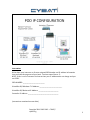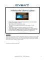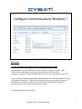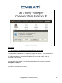
1
Copyright 2011-‐2013 – CYBATI/cyba:.org 1 This area le? inten:onally blank. Copyright 2011-‐2013 – CYBATI/cyba:.org 2 Instruc(ons Write down your Instructor or Proctor assigned POD Number and IP address informa:on here and take this page out of your book. You have two of them. J NOTE: If this is not an instructor led course then your IP addresses do not change and you are POD 1. POD NUMBER: _________________________ VirtualBox O/S Windows 7 IP Address: __________________________ VirtualBox O/S Backtrack IP Address: _______________________ Controller IP Address: ___________________________________ (Instruc:ons con:nued on next slide) Copyright 2011-‐2013-‐2012 – CYBATI/ cyba:.org 3 Instruc(ons This screen provides the current RUN mode (REMOTE) and the current status of inputs (I) and outputs (O). Pressing the momentary push buYons or toggling the ON/OFF switches, you will no:ce that the PLC indicates the current state of the inputs. The MicroLogix 1400 (the MicroLogix 1100 is depicted above) will have a smaller font screen with more inputs and outputs indicated. (Instruc:ons con:nued on next slide) Copyright 2011-‐2013 – CYBATI/cyba:.org 4 Instruc(ons Power up all components. If there are any problems during the ini:aliza:on process, please contact your instructor or proctor. You will log in to the computer with the username and password pair of student / cyba:. At this :me you will not log in to the controller. We will discuss the controller screen in a couple of slides. (Instruc:ons con:nued on next slide) Copyright 2011-‐2013 – CYBATI/cyba:.org 5 Instruc(ons DF1 / RS-‐485 is a legacy serial communica:ons interface and protocol. It is s:ll commonly used in industrial environments for direct connec:vity and smaller, legacy deployments. DF1 / RS-‐485 will be used for ini:al configura:on of the controller and por:ons of Lab 2, a?erwards the labs will focus on Ethernet / IP communica:ons. Your instructor or proctor should have assigned a POD number to your group. Unique IP addresses will be used for each POD replacing the leYer P with the number assigned. For example if your group is Pod 1 your IP addresses would be 172.16.1.10 for the controller. (Instruc:ons con:nued on next slide) Copyright 2011-‐2013 – CYBATI/cyba:.org 6 Instruc(ons **** Ask instructor if the laptops are to be assigned via DHCP or sta(c. The commands to set your Windows 7 laptop IP address sedng are scripted. Open CYBATI_Labs on the desktop , then click on the folder Labs, then the folder ip_address_assignment. Open Windows and then click on your pod number’s batch file. You can verify the sedngs by opening the Shortcuts folder on the desktop and then clicking on “Network Connec:ons”. Right click on Local Area Connec:on and select Proper:es. Double-‐click on “Internet Protocol Version 4 (TCP/IPv4) and modify the sedngs are prescribed by your POD number and shown in the slide. (Instruc:ons con:nued on next slide) Copyright 2011 – CYBATI/cyba:.org 7 Instruc(ons **** Ask instructor if the laptops are to be assigned via DHCP or sta(c. The commands to set Backtrack’s IP address at run:me are scripted. These commands will need to be re-‐issued at each restart. Open CYBATI_Labs on the desktop, then Labs, then ip_address_assignment, then Backtrack and then select your pod number. Run the command in the terminal. You can verify these sedngs by opening the command terminal prompt and execu:ng ifconfig eth0 and route –n. (Instruc:ons con:nued on next slide) Copyright 2011 – CYBATI/cyba:.org 8 Instruc(ons Open RSLinx Classic from the Windows 7 Desktop by clicking the Start buYon and typing RSLinx in the “Search programs and files” input box. Select RSLinx Classic. Review the ac:ve connec:ons under AB_DF1-‐1, DH-‐485. You should see a 01 ML1[1,4]00 without an X through it. If you see an X through the icon you are currently unable to communicate with the controller and there is a port conflict and proceed to the sec:on below FIX MY COM PORT. If you see the un-‐Xed version of the controller icon, right-‐click on it and select Driver Diagnos:cs. You should see the Total Packets Sent and Replay Packets Received incremen:ng sequen:ally. Close the windows – you have now validated the previously defined serial communica:ons to the controller. FIX MY COM PORT -‐-‐-‐-‐-‐-‐-‐-‐-‐-‐-‐-‐-‐-‐-‐-‐-‐-‐-‐-‐-‐-‐-‐-‐-‐-‐-‐-‐ We are going to find out what com port has been assigned to the USB to RS485 interface. We have yet to be able to find a way to hard code this value a?er imaging worksta:ons using Clonezilla. 1. In Windows 7 click the Start buYon; then, type “device manager” in to the “Search programs and files” input box. Click on device manager located in the Control Panel category. 2. Select the Ports (COM & LPT) menu tree item and iden:fy what COM port has been selected for the DGYCGK device. Write this COM port down, or memorize it – whichever you prefer. 3. Using RSLinx Classic, select the Communica:ons menu item and then Configure Drivers. 4. Click the AB_DF1-‐1 driver which should also indicate a Status of Conflict. Select “Configure” 5. Change the COM port to equal the COM port you iden:fied earlier and click “Auto-‐Configure”. 6. You will kindly be presented with a pop-‐up sta:ng that the process failed; however, click OK and you will see in the status panel next to Auto-‐Configure you were successful. Click OK and exit out of RSLinx Classic. 7. Now con:nue with the part a?er “FIX MY COM PORT” (Instruc:ons con:nued on next slide) Copyright 2011-‐2013 – CYBATI/cyba:.org 9 Instruc(ons The controller IP address can only be managed through DHCP (Dynamic Host Configura:on Protocol) or using RSLogix Micro Starter Lite (RSLogix Micro). Open RSLogix Micro from your desktop. You will be prompted again by User Account Control to allow this applica:on to run, select yes. Select the RSLogix Micro Menu Comms / System Comms. As reviewed earlier in RSLinx, an AB_DF-‐1 / DH-‐485 communica:on channel should be established to the MicroLogix 1100 or MicroLogix 1400. If you do not see this channel contact your instructor or proctor. Click the OK buYon. Select the OFFLINE drop-‐down box and then Go Online. This will ini:ate a connec:on with the controller allowing you to download the current ladder logic. Select Create New File and RSLogix will establish the connec:on, download in ac:ve ladder-‐logic and return back to the programming interface. (Instruc:ons con:nued on next slide) Copyright 2011 – CYBATI/cyba:.org 10 Instruc(ons Double-‐click on Channel Configura:on, then click on the Channel 1 tab. Channel 0 is the DF-‐1 / RS-‐485 configura:on tab while Channel 1 is the E/IP configura:on tab. Uncheck the default sedng of BOOTP Enable. Configure the IP address as shown replacing the Pod number P with your value. When complete click Apply. A pop-‐up will occur providing a Warning message that communica:on on Channel 1 will be lost. This is ok as we are not communica:ng via Channel 1, we are configuring the controller using Channel 0. Click Apply. Then Click OK. ML1100 PLC Configura:on IP address: 172.16.P.30 Subnet Mask: 255.255.255.0 Gateway Address: 172.16.P.1 LEAVE NAME SERVERS BLANK or DEFAULTS To verify the new sedng directly on the ML1100, on the physical controller press the ESC buYon, then down arrow to Advance Set, push the OK buYon. Next use the down arrows to select ENET CFG. You should now see the MAC address and assigned IP address on the controller LCD screen. (Instruc:ons con:nued on next slide) Copyright 2011 – CYBATI/cyba:.org 11 Instruc(ons In Windows 7, launch RSLogix Micro from the desktop using the Start buYon and “Search for programs and files”. Click to create a “New” Project and then name and select the type of processor (you will need to review the hardware informa:on label located on the side of the PLC). Note the types of processors available to you may vary from what is depicted on the slide. Click the OK buYon to con:nue. (Instruc:ons con:nued on next slide) Copyright 2011-‐2013 – CYBATI/cyba:.org 12 Instruc(ons You will now be presented with the configura:on screen for the controller, its communica:ons and ladder logic programming. We will review other proper:es within the controller later in this laboratory. Click on the first rung of the ladder 0000. It will turn red (as shown in greyscale in the book) showing that it is the currently selected rung. Next click on the normally open contact (depicted in the slide as “Examine if Closed”), this will place an empty contact (Examine if Closed [XIC]) in the rung. If you remember from lecture this means “look for a 1” within the input register loca:on inside the PLC. (Instruc:ons con:nued on next slide) Copyright 2011-‐2013 – CYBATI/cyba:.org 13 Instruc(ons Now add the address of the first contact, I:0/2 (Note the address is the number zero not the leYer O). A?er you complete naming the contact press enter. A popup window will display allowing you to enter a descrip:on of the variable, enter “Green Push BuYon”. Press the OK buYon. Next click on the output energize symbol (OTE) as shown in the slide. This condi:on will write a 1 to the register loca:on if the preceding condi:ons in the ladder logic rung are true. (Instruc:ons con:nued on next slide) Copyright 2011-‐2013 – CYBATI/cyba:.org 14 Instruc(ons Next enter the output contact to energize (variable loca:on to write a 1). This loca:on will be the output contact of our green light O:0/1. Press Enter and use the descrip:on of “Green Light”. Press the OK buYon. (Instruc:ons con:nued on next slide) Copyright 2011-‐2013 – CYBATI/cyba:.org 15 Instruc(ons Next click on rung 0000 turning it red (depicted as 1 in slide). Click on the “Rung Branch” symbol (shown highlighted by mouse hovering in sec:on A in slide) Now le? click on the right side of the branch and hold/drag your mouse to the right side of the contact I:0/2 (as shown in 2 in slide). A?er the small box is highlighted in green, let go and it will wrap the branch around the Contact I:0/2. Now click on the le? lower corner of the branch (red loca:on shown in 3) this will turn the corner red. Click on the “Examine if Close” (XIC) to have the processor look for a zero at the register loca:on. Enter the output of O:0/1 then click enter. You will no:ce that the program automa:cally provided the previous descrip:on to the output. You have just created the first part of a sealed-‐in rung that has the ability to remember the state of the momentary push buYon. This essen:ally creates a toggle with a push buYon which is typically used to start a motor. Another programming op:on exists to provide sealed in rungs – these are called latches. We will see a latch later when we review crea:ng HMI alarms. It is really the PLC programmer’s preference and what func:ons are integrated in to the PLC. (Instruc:ons con:nued on next slide) Copyright 2011-‐2013 – CYBATI/cyba:.org 16 Instruc(ons Now click on the right top side of the branch, this will also turn red (as shown in 1). Next click on the “Examine if Open” (XIO which means look for a zero) symbol and drag it to the red box. Address this loca:on as I:0/3. This is the input for your red push buYon. Enter a descrip:on “Red Push BuYon” Next click on the “Verify Project” buYon to validate the program. If there are any coding errors another area will display on the screen describing where you have made a mistake. If everything is successfully you should no longer see the edit tages on the le? of the rung. (eeeee). Next you will download your program to the processor. (Instruc:ons con:nued on next slide) Copyright 2011-‐2013 – CYBATI/cyba:.org 17 Instruc(ons 1. Click on the Menu (Comms) then Download. This will download the program to the processor. 2. You will be prompted to save the current program to the worksta:on. Save it to the desktop and name it Push_BuYon. Next a popup windows will display with revision notes, Click OK. 3. Another popup windows will ask if you want to proceed with the download from the program to the processor (your processer name and type may be different). Click Yes. 4. You will next receive a WARNING prompt pertaining to loss of communica:ons on channel 1, this is the Ethernet/IP channel. This Is OK. We will re-‐configure channel 1 in the next sec:on. You will no:ce that the controller must be power cycled for the Ethernet configura:on to be removed. Un:l such :me you can review the current IP configura:on on the controller using the LCD screen and pings will s:ll be successful. Then you will be prompted to place it in the RUN mode, click YES and go online also… (Instruc:ons con:nued on next slide) Copyright 2011-‐2013 – CYBATI/cyba:.org 18 Instruc(ons Now it is :me to test your program. Click on the “Remote Program” drop down box and select Run. This will place the controller in Remote Run mode. Push the Green Push BuYon, this should turn on the Green Light on and it should stay on. In the RSLogix Micro window you will see the variables alterna:ng between lit green and unlit as the variables are iden:fied as True. If the en:re ladder rungn is true the output is wriYen a one (energized). The light stays on as the push buYon input shuts off because the wriYen logic keeps the lamp on and seals (latches) the circuit. Now push the RED push buYon, this being a normally closed circuit (XIC, “Examine if Closed”, look for a 1) breaks the latch when the contact opens turning off the Green lamp. You just created the ladder logic to start and stop a motor. (Instruc:ons con:nued on next slide) Copyright 2011-‐2013 – CYBATI/cyba:.org 19 Instruc(ons Next “Go Offline” to make the following edits. Some PLCS allow you to do online edi:ng including the ML1100 however at this :me we are not going to perform this. If you are interested in reviewing how this works, a?er performing this lab return to this page and perform the addi:onal sec:on below. Click on the down arrow next to the REMOTE RUN and click Go Offline, no:ce that there are other op:ons on this dropdown menu that you may also use to download the program to the processor, to upload the program from the processor and to place the processor in test mode. Right-‐click on the first ladder rung and select “Insert Rung”. This will add a new rung to our ladder. ADDITIONAL LAB STEP AFTER COMPLETING LAB. Edi:ng online programs requires right-‐clicking on the RUNG and selec:ng “Start Rung Edits” while the processor is s:ll in Remote Run mode. The rung will then be duplicated showing the original Rung “rrrrr” and edit Rung “eeee”. Once you have made the rung edits select Accept Rung Edit. The Rung will now be labeled with “IIIII”. Next select Test Edits (program verify) and finally Assemble edits to merge the edited rung(s) with the rest of the program. (Instruc:ons con:nued on next slide) Copyright 2011-‐2013 – CYBATI/cyba:.org 20 Instruc(ons Now insert the logic depicted in the slide. Note that you will need to use “Normally Closed”, XIC or look for a zero logic to complete this rung. This rung allows the toggle switches to simulate sensors that must be providing posi:ve input for the output to be energized. These sensors (toggles) could be various safety controls that must be in a specific state for the output to be energized while the motor (green light) is not running. Complete the ladder logic, validate the program, download it to your processor and Run it. (Instruc:ons con:nued on next slide) Copyright 2011-‐2013 – CYBATI/cyba:.org 21 Instruc(ons Once complete you should be able to toggle the switches and monitor the inputs and outputs within RSLogix as shown in the slide. (Instruc:ons con:nued on next slide) Copyright 2011-‐2013 – CYBATI/cyba:.org 22 Instruc(ons Now open the Input and Output register tables located in the Data Files folder. These serve as bit loca:ons for input and output status indicators and are sta:cally allocated by the firmware. Manipulate the inputs to toggle the green and red lights while watching the specific bits flip between zero and one. Also note that the descrip:on tag is displayed in the Desc: box during mouse hovers. This will also be important as we transi:on to the HMI and then communica:on channels. You have completed part I of 3 of this laboratory. Con:nue to the next sec:on. (Instruc:ons con:nued on next slide) Copyright 2011-‐2013 – CYBATI/cyba:.org 23 Lab Sec(on Introduc(on Lab 2 contains 3 programming components. Ladder Logic Programming Ladder logic programs provide the industrial automa:on of legacy manual func:ons. The logic allows for inputs (sensors) to control actuators (outputs) with logic programming defined to enable the appropriate control and safety of opera:ons. The goal is to develop a simple latch circuit, by using the momentary push buYons Green (I:0/2) and Red (I:0/3). The Green push buYon will start the process (turn on Green light O:0/1) and the Red push buYon will stop the process (turn off Green light O:0/1). Further we will program the Red light (O:0/3) to func:on as an alarm light enabled when the process is off (Green light not on). We will also program three toggle switches to serve as alarm by-‐ passes disabling the Alarm from ac:va:ng. You will develop the program, download it to the CPU, edit the ladder-‐logic and download it again. ********* Remote Ethernet/IP I/O to an HMI In this exercise you will program remote Ethernet/IP connec:vity between the controller and a HMI HMI Configura(on of Push BuRon Controls and an Alarm In this exercise you will program the CYBATI_HMI Windows applica:on with the visual control, indica:ons and alarms of the PLC func:oning states. (Instruc:ons con:nued on next slide) Copyright 2011-‐2013 – CYBATI/cyba:.org 24 Instruc(ons You will need to restart the controller to remove the IP address sedngs and then we will re-‐apply them. You will no:ce that you will lose communica:ons to the processor from within RSLogix. A?er the processor is back online, click the Retry buYon. Verify that the IP address sedngs are removed using the LCD panel. To verify the removal of the IP address on the ML1100, on the physical controller press the ESC buYon, then down arrow to Advance Set, push the OK buYon. Next use the down arrows to select ENET CFG. You should now see the MAC address and no assigned IP address (-‐.-‐.-‐.-‐) on the controller LCD screen. PLC Configura:on IP address: 172.16.P.30 Subnet Mask: 255.255.255.0 Gateway Address: 172.16.P.1 LEAVE NAME SERVERS BLANK or DEFAULTS Place the controller in REMOTE PROG mode. Double-‐click on Channel Configura:on, then click on the Channel 1 tab. Channel 0 is the DF-‐1 / RS-‐485 configura:on tab while Channel 1 is the E/IP configura:on tab. Uncheck the default sedng of BOOTP Enable. Configure the IP address as shown replacing the Pod number P with your value. When complete click Apply. A pop-‐up will occur providing a Warning message that communica:on on Channel 1 will be lost. This is ok as we are not communica:ng via Channel 1, we are configuring the controller using Channel 0. Click Apply. Then Click OK. To verify the new sedng directly on the ML1100, on the physical controller press the ESC buYon, then down arrow to Advance Set, push the OK buYon. Next use the down arrows to select ENET CFG. You should now see the MAC address and assigned IP address on the controller LCD screen. To complete the verifica:on process Ping your controller from the worksta:on. Click the lower-‐le? Windows icon and then type cmd in the text box. This will open a command terminal. Type ping 172.16.P.30 replacing the P with your pod number. (Instruc:ons con:nued on next slide) Copyright 2011-‐2013 – CYBATI/cyba:.org 25 Instruc(ons In Windows 7 launch CYBATI_HMI using the Start buYon (Make sure the green license dongle is inserted in to an open USB port) and “Search for programs and files”, then click Project / New. Create and select the Desktop folder MyHMI and click Ok. Click the “Log In” buYon using the complex password for the Director username. You now have a new HMI project which you will configure a connec:on to your controller and a visual indicator for the Green indicator lamp’s on and off states. (Instruc:ons con:nued on next slide) Copyright 2011-‐2013 – CYBATI/cyba:.org 26 Instruc(ons Within the CYBATI HMI applica:on, select Communica:ons / AB PCCC Masters and then Micrologix. There is an exis:ng configura:on (ML1100) – we will use this configura:on later in the lab. Click New and enter the name MyPLC. Click OK. (Instruc:ons con:nued on next slide) Copyright 2011-‐2013 – CYBATI/cyba:.org 27 Instruc(ons Now configure the IP address of the MicroLogix controller, 172.16.P.30 replacing the P with your Pod number. The port number is the default number (TCP/44818) and is not modified. Next click “Test”. This will bring up the test dialogue screen to aYempt to make a connec:on, register a session, unregister a session and then disconnect with the PLC. Press the Test buYon and similar results as shown on slide should be seen. If you do not have a successful result contact your instructor or proctor. You have now successfully configured a connec:on from the HMI / OPC system to the controller. (Instruc:ons con:nued on next slide) Copyright 2011-‐2013 – CYBATI/cyba:.org 28 Instruc(ons Next you must define which slots (data registers) the HMI / OPC agent should write to and read from. The configura:on is using Table words (16 bits). For this example check the box “read output cards” and enter 1 next to slot 1. This will instruct the HMI / OPC agent to read the output bits associated with Slot 1 in the Micrologix 1100. Later in this lab you will see addi:onal logic read from and wriYen to using variables and inputs. Once complete, click OK, and OK again. (Instruc:ons con:nued on next slide) Copyright 2011-‐2013 – CYBATI/cyba:.org 29 Instruc(ons Next is to establish the specific Points or Tags that will be read from the controller. Select Configura:on / Points from the menu. Then click on “New Point” within the configura:on box. (Instruc:ons con:nued on next slide) Copyright 2011-‐2013 – CYBATI/cyba:.org 30 Instruc(ons This new tag / point will be to read the register associated with the Green Light output. Name the tag “Green_Light”, select type Digital, ensure the port is “MyPLC”, the source is the Output I/O. No:ce that the output loca:on now contains an addi:onal zero. This zero represents the first slot. If addi:onal I/O were added to this controller then the first value could be a 1 or a 2. In this case it is O:0.0/1. The access rights at this :me will be “read”. Select Type Digital in the upper-‐right hand corner of the display panel. Addi:onal sedngs within the interface are outside the scope of this course; however, they may serve as aYack vectors if they were manipulated in any way. If you are interested in learning more about the variables select the Help buYon on the lower-‐le? of the screen. Click Ok. (Instruc:ons con:nued on next slide) Copyright 2011-‐2013 – CYBATI/cyba:.org 31 Instruc(ons There should now be a new tag/point within the dialog box. Click Ok. (Instruc:ons con:nued on next slide) Copyright 2011-‐2013 – CYBATI/cyba:.org 32 Instruc(ons Next we will configure the graphical interface. Select Configura:on / Graphics. A window will appear, click “New” and enter MyHMI for the Screen name. Click OK. (Instruc:ons con:nued on next slide) Copyright 2011-‐2013 – CYBATI/cyba:.org 33 Instruc(ons On the right side of the configura:on window are many ar:st tools. Select the circle since it is the closet representa:on of the light. Move your mouse to a point on the white background within the editor. Click the le?-‐mouse buYon, holding it down, drag down and to the right un:l you have a circle that is similar in size to the light. You may even be interested in recoloring the circle. While the circle is selected you may choose in color available within the paleYe. Of course, green may be the best choice. (Instruc:ons con:nued on next slide) Copyright 2011-‐2013 – CYBATI/cyba:.org 34 Instruc(ons Double-‐le? mouse click the circle to bring up the configura:on dialogue for the circle. Check the box “Enabled” next to Hide/Show. A pop-‐up dialogue will appear allowing you to iden:fy a “Source”. Click the “Source” buYon and select the only tag/point that is configured “Green_Light”. Click Ok. Next check the “Invert” box as we want the circle to appear when the bit is one (Output energized) and the circle to disappear when the bit is zero (Output de-‐energized). Click Ok, then OK. Then click File / Save and File / Exit. Then Save the MyHMI screen within the Screen pop-‐up window. (Instruc:ons con:nued on next slide) Copyright 2011-‐2013 – CYBATI/cyba:.org 35 Instruc(ons Select Monitoring / Start. A pop-‐up window will display several op:ons. Click “Open Window”. If the green light is currently enabled on the controller it should display on the screen with the white background, if it is not enabled the screen should be completely white. Toggle the green light on and off using the momentary push buYons to see how the HMI to PLC communica:ons occurs. You have just configured a HMI to controller SCADA point and an OPC point to republish upstream to another device if this were a larger environment. (Instruc:ons con:nued on next slide) Copyright 2011-‐2013 – CYBATI/cyba:.org 36 Lab Introduc(on Lab 2 contains three programming components. Ladder Logic Programming Ladder logic programs provide the industrial automa:on of legacy manual func:ons. The logic allows for inputs (sensors) to control actuators (outputs) with logic programming defined to enable the appropriate control and safety of opera:ons. The goal is to develop a simple latch circuit, by using the momentary push buYons Green (I:0/2) and Red (I:0/3). The Green push buYon will start the process (turn on Green light O:0/1) and the Red push buYon will stop the process (turn off Green light O:0/1). Further we will program the Red light (O:0/3) to func:on as an alarm light enabled when the process is off (Green light not on). We will also program three toggle switches to serve as alarm by-‐passes disabling the Alarm from ac:va:ng. You will develop the program, download it to the CPU, edit the ladder-‐ logic and download it again. Remote Ethernet/IP I/O to an HMI In this exercise you will program remote Ethernet/IP connec:vity between the controller and a HMI ********* HMI Configura(on of Push BuRon Controls and an Alarm In this exercise you will program the CYBATI_HMI Windows applica:on with the visual control, indica:ons and alarms of the PLC func:oning states. (Instruc:ons con:nued on next slide) Copyright 2011-‐2013 – CYBATI/cyba:.org 37 Instruc(ons Programming points, defining alarms, reprogramming controllers and building screens can be a painstaking and tedious process. Therefore for the sake of :me and sanity we are going to fast-‐forward the development of the PLC ladder logic and HMI / OPC agent configura:on. You will now load in to the controller and HMI code that mimics the physical controller I/O within the HMI. The logic also includes an alarm if an aYempt is made within the HMI to enable a toggle switch requiring the operator to use the HMI to acknowledge the alarm. Once loaded you will need to review the new AB PCCC card I/O sedngs, the new points, the alarm, acknowledgement and the ML1100 ladder logic loaded in to the controller. The logic will be quite different and an addi:onal Binary file will be used on the PLC. First, open the CYBATI Labs folder on the desktop. Browser to Ladder_Logic and open “SEALED_IN_TOGGLE_HMI_ALARM.RSS”. You will next need to configure the IP sedngs for your POD. (Instruc:ons con:nued on next slide) Copyright 2011-‐2013 – CYBATI/cyba:.org 38 Instruc(ons (YOU CAN OMIT THIS STEP SINCE WE ARE USING DHCP; HOWEVER, YOU MAY WANT TO HARD CODE THE IP ADDRESS DURING THE RED TEAM / BLUE TEAM EXERCISE ON FRIDAY AND THIS INFORMATION WILL BE USEFUL) Double-‐click on Channel Configura:on, then click on the Channel 1 tab. Channel 0 is the DF-‐1 / RS-‐485 configura:on tab while Channel 1 is the E/IP configura:on tab. Uncheck the default sedng of BOOTP Enable. Configure the IP address as shown replacing the Pod number P with your value. When complete click Apply. A pop-‐up will occur providing a Warning message that communica:on on Channel 1 will be lost. This is ok as we are not communica:ng via Channel 1, we are configuring the controller using Channel 0. Click Apply. Then Click OK. PLC Configura:on IP address: 172.16.P.30 Subnet Mask: 255.255.255.0 Gateway Address: 172.16.P.1 LEAVE NAME SERVERS BLANK or DEFAULTS To verify the new sedng directly on the ML1100, on the physical controller press the ESC buYon, then down arrow to Advance Set, push the OK buYon. Next use the down arrows to select ENET CFG. You should now see the MAC address and assigned IP address on the controller LCD screen. (Instruc:ons con:nued on next slide) Copyright 2011-‐2013 – CYBATI/cyba:.org 39 Instruc(ons Review the ladder logic and the new branches and logic added to handle HMI interac:ons. Each HMI variable is defined with an “HMI” tag and stored in the B3 register table. You will also no:ce new logic, a latch. Latches operate like sealed-‐in logic except they are easier to maintain. A latch is used in this example to maintain the state of the alarm light even a?er the rung is no longer true. The Alarm Light is unlatched when either the HMI acknowledge buYon is pressed (the HMI sets the register bit to 0) or the two momentary push buYons are depressed simultaneously. The following two slides zoom on the ladder logic for review. (Instruc:ons con:nued on next slide) Copyright 2011-‐2013 – CYBATI/cyba:.org 40 Instruc(ons Review then con:nue. (Instruc:ons con:nued on next slide) Copyright 2011-‐2013 – CYBATI/cyba:.org 41 Instruc(ons Review then con:nue, wri:ng down any ques:ons you may be interested in asking during the lab review. (Instruc:ons con:nued on next slide) Copyright 2011-‐2013 – CYBATI/cyba:.org 42 Instruc(ons Next download the new logic to the controller using RSLogix. Select “Download” (1), then click OK (2), click Yes (3, note during this step you may receive an addi:onal prompt that this program was not wriYen for your processor – con:nue and the program will be modified to support the addi:onal capabili:es), then Yes (4), then Yes (5), then Yes (6). (Instruc:ons con:nued on next slide) Copyright 2011-‐2013 – CYBATI/cyba:.org 43 Instruc(ons The project must be loaded in to CYBATI_HMI. Close the CYBATI_HMI and then re-‐open it. Click Project / Open and browse to the network drive CYBATI LABS / HMI / CYBATI_Trainer. Click OK. You will now need to modify this default project to use your controller’s IP address. Unless you are Pod 1, change the IP address of the ML1100 controller configura:on located in the menu item Communica:ons / AB PCCC Masters / Micrologix. Next click the menu item Monitoring / Start. (Instruc:ons con:nued on next slide) Copyright 2011-‐2013 – CYBATI/cyba:.org 44 Instruc(ons You should now see the trainer, events, alarms, and three buYons (3). This environment mimics the state of the physical trainer unit within the HMI. The HMI also can control the push buYons using mouse-‐clicks, acknowledge the alarm and aYempt to modify the state of the toggle switches (with an alarm generated). Now that the new ladder and HMI logic is loaded, you will want to review the new AB PCCC card I/O sedngs, the new HMI / OPC points, the alarm, acknowledgement and the ML1100 ladder logic loaded in to the controller. Take this :me at this step to use your skills learned while crea:ng the green push buYon HMI. You may need to review earlier steps to remember where to find the points, card I/O sedngs, and screen configura:on op:ons – especially during the small-‐scale model scenarios and red team / blue team exercise. We will also step through the configura:on in the following steps. (Instruc:ons con:nued on next slide) Copyright 2011-‐2013 – CYBATI/cyba:.org 45 Instruc(ons The CYBATI trainer HMI requires addi:onal I/O than just reading the output tags. In this case the I/O also includes read and wri:ng the inputs and a binary file that is used to store HMI and alarm variables. View these specific data files as they are ac:vely read by the HMI using the AB PCCC Micrologix Reads panel. Open Communica:ons / AB PCCC Masters / Mircologix (1), then click on Edit (2) and finally the “Test” buYon (3). Review each word (16 bits) as it is read and displayed. Try manipula:ng the controller physical inputs and outputs while Tes:ng. (Instruc:ons con:nued on next slide) Copyright 2011-‐2013 – CYBATI/cyba:.org 46 Instruc(ons Remember earlier in this lab you reviewed the actual data files within the controller as the inputs and outputs were manipulated. Open these Input and Output data files within RSLogix while reviewing the Reads Tes:ng output from the HMI so?ware. The words should match as the HMI reads the sedngs. Toggle the inputs and outputs while watching these tables. (Instruc:ons con:nued on next slide) Copyright 2011-‐2013 – CYBATI/cyba:.org 47 Ques(ons 1. What authen:ca:on methods were used to configure the PLC, HMI points? 2. How many other logical opera:ons are embedded in the MicroLogix 1100 or 1400? (see View / Instruc:on PaleYe within RSLogix) 3. How many points does your environment have? What is the expected scan rate (reques:ng point data and receiving a response)? Does the scan rate maYer? 4. How large is the aYack surface? Answer this ques:on thinking about both cyber and physical-‐cyber (physical aYack crea:ng a cyber event/backdoor). (Instruc:ons con:nued on next slide) Copyright 2011-‐2013 – CYBATI/cyba:.org 48 Instruc(ons Forces require a bit or collec:on of bits to be a zero or one regardless of the current logical state of the applica:on. Forces are typically enabled for troubleshoo:ng or opera:onal enhancements or failures. Try enabling a force as depicted in the slide above. 1. Select the item to force a bit either on or off (0 or 1). The slide depicts the “Green Push BuYon”. Right click on the item and select Force On. 2. You will no:ce the item in the logical program is altered to indicate that the bit is >ON. 3. You will also no:ce that Forces are now Installed and Enabled. Copyright 2011-‐2013 – CYBATI/cyba:.org 49 Instruc(ons Use Backtrack to perform a NMAP scan of the controller. Remember If you are star:ng BackTrack from power-‐up you may need to set the IP address and subnet mask (see Lab 1 for more details, 172.16.P.20), if you are performing this lab in a classroom sedng then we are using DHCP. We recommend using the nmap parameters represented in the slide for faster scan results. For more informa:on about nmap flags use man nmap from the command line. IF TAKING THIS CLASS INSTRUCTOR-‐LED, DO NOT PERFORM THE UDP SCANS DURING CLASS TIME (nmap2.sh and nmap6.sh). YOU CAN START THESE SCANS AT THE END OF CLASS DAY. In Backtrack select “CYBATI shortcuts” from the desktop. Click on nmap scripts to launch a terminal window in the Lab 4 directory. Each nmap command is scripted to accept your POD number. Replace the leYer P below with your pod number. # ./nmap1.sh P # ./nmap2.sh P 1. AYempt an NMAP scan while controller is powered up, but offline. 2. AYempt an NMAP scan while controller is online and you are performing HMI and manual opera:ons. 3. If a web server is found perform HTTP banner grabbing. Were there any result or opera:onal differences between version 1 and 2? Did you note any iden:fying characteris:cs that may be used within shodanHQ? Did you see any different results between the TCP common ports scan and the TCP all ports scan? (Instruc:ons con:nued on next slide) Copyright 2011-‐2013 – CYBATI/cyba:.org 50 Instruc(ons During the next 20 minutes review the RSLogix controller proper:es iden:fied in the slide to locate poten:al risks. Use the Help Dialogue within RSLogix to learn about the specific sedngs. Also take a few minutes to think of physical aYack strategies. Document your most interes:ng findings below, we will discuss them in class at the end of this laboratory. We will further review these sedngs in later labs. (Instruc:ons con:nued on next slide) Copyright 2011-‐2013 – CYBATI/cyba:.org 51 Instruc(ons DO NOT PHYSICALLY DAMAGE THE CONTROLLER OR ITS CONNECTIONS. YOU CAN INVESTIGATE THE LCD PANEL AND PHYSICAL CONNECTIONS. DO NOT ATTEMPT TO MAKE ANY WIRES EXPOSED or CONTACTS WITH ANYTHING WHILE TURNED ON. Review the physical panels located on the controller. How could someone use this physical access to manipulate the inputs, outputs or processing logic? Think about both Physical and Physical-‐cyber aYacks. Write down some ideas and then con:nue, we will discuss your ideas in class. • Physical aYacks cons:tute physically rendering the device unusable and/or iden:fying physical means to manipulate the device func:onality. • Physical-‐cyber aYacks cons:tute physically manipula:ng the device and then performing a cyber aYack based upon the physical modifica:ons. (Instruc:ons con:nued on next slide) Copyright 2011-‐2013 – CYBATI/cyba:.org 52 Instruc(ons Ensure your physical toggle inputs are as follows I:0/0 off (down) [1st toggle], I:0/1 on (up) [2nd toggle], and I:0/4 off (down) [3rd toggle]. Now open data table 0, the output file. Enter 1’s for each output loca:on O:0/0 (motor), O: 0/1 (green light), O:0/2 (yellow light), O:0/3 (red light) and O:0/4 (white light). What happens to the outputs on the PLCs? Why is output O:0/3 not ligh:ng up? Hint: Review the ac:ve state of ladder logic in RSLogix. Of course, note how you are directly able to manipulate the bits in the data table (or at least some of them; you are in conten:on with the running ladder logic). Flip all the bits back to zero before con:nuing. (Instruc:ons con:nued on next slide) Copyright 2011-‐2013 – CYBATI/cyba:.org 53 Instruc(ons The S2 data file allows a program to view the current opera:onal status of the PLC as well as make some modifica:ons. S2:30 – S2:55 are programmable interrupts programs can use to ensure certain events are processed :mely. S2:28 is the watchdog :mer that monitors the PLC scan :me to ensure the scan rate is appropriate and if too long with create a halt condi:on. If a fault were to occur the S2:29 program will run, if there is no program then the processor will halt. Tab through the individual sedngs using the “Help” dialogue box. Op:onally change the display to Radix to binary. This will display the S2 data file as binary words. Hovering over each bit will provide details of its opera:on within the processor. You can return back to the original view by selec:ng Radix: Structured. (Instruc:ons con:nued on next slide) Copyright 2011-‐2013 – CYBATI/cyba:.org 54 Instruc(ons Select the Errors tab and enter a 1 for “Major Error Execu:ng User Fault Rtn. S:5/3. Press Enter. What happened? The processor just faulted and since there is no addi:onal rung in the program to manage this fault the processor halted. The physical processor now has an amber indicator enabled next to the Fault word and RSLogix has labeled in red “FAULTED”. More informa:on about the fault code is available in the “Error Descrip:on pane”. Select the combo-‐box FAULTED and select then “Clear Fault”. Click Yes at the prompt. The processor is not in Remote Program mode. To return the processor back to the normal opera:onal state select Remote Run. Spend no more than 5 minutes exploring other available sedngs within the S2 data :me. (Instruc:ons con:nued on next slide) Copyright 2011-‐2013 – CYBATI/cyba:.org 55 Instruc(ons 1. Launch Armitage. Armitage is a graphical interface to Metasploit. 2. You will need to connect Armitage to an opera:onal RPC server interface of Metasploit. If not available Armitage starts it for you. Click connect 3. Now click “Yes” to start the Metasploit RPC server. 4. Armitage will now try to connect to Metasploit – this may take up to one minute. (Instruc:ons con:nued on next slide) Copyright 2011-‐2013 – CYBATI/cyba:.org 56 Instruc(ons 1. The Armitage interface provides a view of all of the loaded Metasploit modules in a tree hierarchy on the le? side of the screen. The boYom of the screen provides a tabbed view which can grow to more tabs as individual jobs are processed or more hosts are ac:vely being aYacked. 2. Cortana is a research project out of DARPA’s cyber fast track program. Cortana provides a scripted interface to Metasploit results and modules increasing the ability to not only collect data, filter through and automa:cally make decisions but also do so through a team server allowing mul:ple red team par:cipants to use Armitage, Cortana and Metasploit through a centralized backend. (Instruc:ons con:nued on next slide) Copyright 2011-‐2013 – CYBATI/cyba:.org 57 Instruc(ons Located in auxiliary/cyba:/micrologix_fault. Read the Metasploit descrip:on. You can review the source code of the module at /root/.msf4/modules/auxiliary/cyba:/ micrologix_fault.rb This specific module was created by CYBATI personnel to understand the difficulty of crea:ng vulnerable by design modbus modules. Using the CYBATI training kit this module was developed in just under two hours. The greatest challenge was to define the appropriate wireshark filters to iden:fy the exact command that create the fault. The other necessary requirement was to have the appropriate wireshark dissector to understand the data being transmiYed. Exactly how this will be discussed in a different lab. (Instruc:ons con:nued on next slide) Copyright 2011-‐2013 – CYBATI/cyba:.org 58 Instruc(ons Metasploit modules can be executed directly from the command line using msfcli. This example runs the CYBATI MicroLogix fault module against 172.16.1.30 #msfcli auxiliary/cyba(/micrologix_fault RHOST=172.16.1.30 e (Instruc:ons con:nued on next slide) Copyright 2011-‐2013 – CYBATI/cyba:.org 59 Instruc(ons Metasploit modules can also be operated and interacted with using the CORTANA scrip:ng language. The example located in the CYBATI_Labs/Scripts/cortana_micrologix_fault_service_add file waits for a service to be added on port 44818. Once added to the Armitage database the script executes launching the CYBATI micrologix fault Metasploit module. Many script examples are available in the Cortana User Manual located in the CYBATI_Labs/Whitepapers folder. To use the Cortana script perform the followings steps: 1. In Armitage, Select Hosts, Add Hosts – enter your MicroLogic PLCs IP address and Click Add. Then click OK. 2. Click on the new worksta:on monitor added to Armitage and a green dashed line will surround it. 3. Click Armitage and then Scripts. 4. Click Load and browse to Desktop/CYBATI_Labs/Scripts/cortana_micrologix_fault_service_add 5. Click the Console buYon to open the Cortana console 6. At the cortana> prompt, enter ls and you should see the new script loaded. 7. Enable debugging for this script using the tron cortana_micrologix_fault_service_add command (you can use TAB for auto-‐comple:on of the word). You can see all of the available commands by typing help. 8. Click Hosts, NMAP Scan, Intense Scan, all TCP Ports. Your host will automa:cally be added and click OK. (Instruc:ons con:nued on next slide) Copyright 2011-‐2013 – CYBATI/cyba:.org 60 Instruc(ons For the first part of the laboratory you will play the role of an operator observing the environment. 1. Launch the CYBATI_HMI from the desktop Shortcuts folder. 2. Open the CYBATI_Trainer HMI. Select Project and Browse for folder CYBATI_Labs / HMI / CYBATI_Trainer. Click OK. 3. Change the IP address configured in the HMI communica:ons sedng. Communica:ons / AB PCCC Masters / Micrologix. Click Edit Sedngs and enter your Pod’s IP Address (e.g. 172.16.P. 30). Click Test to validate connec:vity. Is connec:vity fails contact your instructor or proctor. 4. Launch RSLogix Micro Starter from the Shortcut folder. Click File / Open. Choose CYBATI_Labs / Ladder_Logic / Sealed_IN_TOGGLE_HMI_ALARM. 5. Select Comms / Download. Click OK and complete the download leaving the PLC in the state of REMOTE RUN. 6. Now go back to the CYBATI_HMI and select Monitoring / Start to launch the HMI. 7. You should now have a HMI that correctly represents the state of the field equipment (I/O Trainer Inputs and Outputs). (Instruc:ons con:nued on next slide) Copyright 2011-‐2013 – CYBATI/cyba:.org 61 Instruc(ons We will now perform a Physical – Cyber aYack against the operator’s worksta:on. Located within your plas:c container in the kit is a USB device. Ensure the CYBATI Trainer HMI is launched and opera:onal. Test the inputs and outputs to make certain the indicators are correct. We have modified the device to prompt you with message boxes while performing the aYack, a true aYack may not be so nice. Now insert the USB device in to an open slot on the CYBATI worksta:on. Click OK at each Message Box to con:nue. If you lose the Message Box or a window pops over it you can click the VBScript icon on the task bar (as shown in the slide). Take a look in Device Manager – do you no:ce anything different? Did you baseline your worksta:on? J STOP HERE – LECTURE WILL CONTINUE (Instruc:ons con:nued on next slide) Copyright 2011-‐2013 – CYBATI/cyba:.org 62 Instruc(ons Open that CYBATI_sketch.ino file located in the arduino labs folder (CYBATI_Labs / Labs / arduino / CYBATI_sketch / CYBATI_sketch.ino. This file contains the source code of the script that is executed once the USB HID is recognized. Note that the device is represented simultaneously as a HID and a storage medium. The addi:onally downloaded and already installed phukdlib.h library is used to allow keystroke manipula:on to the opera:ng. Note that this library is O/S independent, the script will inject keystrokes to any opera:ng system; however, powershell will not be there unless it is a Microso?® Windows® product J. The script ini:alizes the local file system and finds the storage device with the name CYBATI. The storage device will eventually contain the files located in the disk folder. The .VolumeLabel file contains the name of disk “CYBATI”. The exec file contains the VBScript that stepped you through the aYack. The tags.pdb and tags_o.pdb are the tags that are swapped in the HMI. (Instruc:ons con:nued on next slide) Copyright 2011-‐2013 – CYBATI/cyba:.org 63 Instruc(ons Kismet is commonly used to perform 802.11 analysis and within Backtrack it is very easy to use. 1. Launch or switchover to the Backtrack VM. 2. Connect the USB ALFA wireless card to computer, it will automa:cally be capture by the Backtrack Virtual Machine. Us 3. Select kismet from the Shortcuts folder located on the Backtrack desktop 4. Respond to the “Terminal colors” ques:on. 5. Accept the warning that Kismet is running as root. This is risky as the kismet wireless parser could have it’s own vulnerabili:es; however, for the purposes of this course and laboratory environment it is acceptable. Click Ok. 6. Click Yes to automa:cally start the Kismet server. 7. Click Start (accept defaults) 8. You will now be presented with the Console window. This is the logging window. You will see a few ERRORs associated with Kismet’s inability to locate a GPS daemon. Kismet can operate with GPS data; however, it is outside the scope of this course to include a GPS lab, although it would be nice to have class outdoors. 9. Click Yes to define a packet source. 10. Enter wlan0, you can verify that this is interface name by typing ifconfig at a console prompt. 11. Click with your mouse or tab to [ Add ]. 12. You should see several INFO log messages iden:fying wireless networks being detected. Click “Close Console Window” in the lower right-‐hand corner. The new version of Kismet launches and will eventually display a TEXT-‐based GUI. The interface by default depicts the discovered networks on top, a graphical depic:on of packets (actually frames since this is layer 2) monitored, and informa:onal expert analysis of the packets received. The right-‐hand tracks the current session sta:s:cs. There are many op:ons within the Kismet interface that you may want to take a few minutes to explore. Use your mouse to click around and also discover the keyboard shortcuts. You should also see the CYBATI SSIDs (e.g. CYBATI-‐CITY-‐*****) (Instruc:ons con:nued on next slide) Copyright 2011-‐2013 – CYBATI/cyba:.org 64 Instruc(ons It will be very helpful for this lab to alter the default view. Select the “Client List” while de-‐ selec:ng GPS Data, BaYery, and the Packet Graph. This will allow us to not only see current access points and SSIDs discovered but also review their associated wireless clients and OUI analysis. It may also be helpful while reviewing a specific network to lock in on its specific channel. The channel is iden:fied under the “Ch” column and can Kismet can be set to not channel hop using the Kismet / Config Channel op:on. (Instruc:ons con:nued on next slide) Copyright 2011-‐2013 – CYBATI/cyba:.org 65 Instruc(ons Several clients will populate for each SSID iden:fied. These clients are automa:cally categorized using Kismet’s OUI file. The OUI file uses the first 6 hexadecimal characters in the device’s MAC address to guess the Manufacturer. (Instruc:ons con:nued on next slide) Copyright 2011-‐2013 – CYBATI/cyba:.org 66 Instruc(ons Open the pcapdump file using wireshark. The capture date and :me is used to iden:fy the correct pcapdump file. The captured data is located in the /root/ directory which is the default directory when opening a command prompt in Backtrack. Open the packet capture file using the syntax # wireshark <name of capture.pcapdump>. Remember that you can use TAB to auto-‐complete the file name. (Instruc:ons con:nued on next slide) Copyright 2011-‐2013 – CYBATI/cyba:.org 67 Instruc(ons Review the capture packets looking for anything that resembles control system components. A hint is depicted above as well as the following OUIs may be helpful. Rockwell 00-‐0F-‐73 (From Documenta:on) automa:on direct / koyo 00-‐E0-‐62 (From documenta:on) hYp://support.automa:on.siemens.com/US/llisapi.dll/32422566? func=ll&objId=32422566&objAc:on=csView&nodeid0=42728754&lang=en&siteid=cseus&aktprim=0&extranet=standard&viewreg=US&load=treecontent#A2 4440281 08-‐00-‐06 (hex) SIEMENS AG Siemens IT Solu:ons and Services, SIS GO QM O Siemensstraße 2-‐4 POB 2353 Fürth 90713 GERMANY 00-‐0E-‐8C (hex) Siemens AG A&D ET Siemensstraße 10 Regensburg 93055 GERMANY 00-‐1B-‐1B (hex) Siemens AG I IA SC EWK PU1, Östliche Rheinbrückenstraße 50 76181 Karlsruhe, Baden WürYemberg GERMANY Company Schneider Electric (Australia) Prefix 00:0C:81 (hYp://hwaddress.com/mac/000C81-‐000000.html) Schneider Electric M340 PLC 000053 ( hYp://www.east-‐med.schneider-‐electric.com/sites/east-‐med/en/support/faq/faq_main.page? page=content&country=EAST_MED&lang=EN&id=FA22767&redirect=true) 006008 (GE versamax PLC / GFK-‐1852 Documenta:on) hYp://www.google.com/url?sa=t&rct=j&q=&esrc=s&source=web&cd=7&ved=0CGcQFjAG&url=hYp%3A%2F%2Fwww.pdfsupply.com%2Fpdfs %2Fg‚1852.pdf&ei=OlNHT7CqIc3lggeX_p2fDg&usg=AFQjCNGMcyqTavZ-‐dux8edeR-‐jFHSZO71A 00-‐a0-‐3d opto 22 snap pac hYp://www.opto22.com/community/showthread.php?t=231&page=1 (Instruc:ons con:nued on next slide) Copyright 2011-‐2013 – CYBATI/cyba:.org 68 Instruc(ons Review the captured data for specific industrial protocols such as Modbus / TCP, DNP3, EthernetIP and ISO-‐TSAP. Simple search filters are available in wireshark to support protocol search. For example, you will only need to type mbtcp for Modbus over TCP, dnp3 for Distributed Network Protocol and enip for Ethernet over IP. If you do capture some control traffic – take a look at the payload constructs – this will be discussed in a different lab. (Instruc:ons con:nued on next slide) Copyright 2011-‐2013 – CYBATI/cyba:.org 69 Instruc(ons GISKismet is a great resource to use when working not only with GPS and map, but also to use as structured query environment for large and/or mul:ple Kismet datasets. GISKismet accepts the xml file developed by Kismet and parses it. It will also parse subsequent datasets and append them to the prior ones as long as you remain with the same directory and use the default giskismet database filename. 1. Open a command terminal in Backtrack. Type giskismet –h. This will show the op:ons that are available. 2. The Kismet capture files you have been collec:ng are in the root folder. Type giskismet –x *.netxml 3. A new file called wireless.dbl will be generated. This file contains the concise wireless data from your captures. 4. Type sqlite3 wireless.dbl to open the database. You can view the lookup tables available to query using the .tables command (e.g. clients and wireless) 5. View the table schema using the .schema clients and .schema wireless commands. This will provide the informa:on necessary to developed the SQL statements. 6. Some sample select statements to issue a. select ESSID from wireless; b. select COUNT(ESSID) from wireless; c. select COUNT(DISTINCT(ESSID)) from wireless; d. select DISTINCT(Encryp(on) from wireless; e. select COUNT(Encryp(on), Encryp(on from wireless GROUP BY Encryp(on; 7. We can even query the database for specific mac addresses, such as ones associated with Industrial manufacturers. a. select mac from clients where mac like ’00:e0:62%’; b. .output industrial-‐mac.txt 8. Even beYer would be to issue a select statement with a join command and combine how many industrial mac addresses are on wireless networks with no or poor wireless protec:on. (Challenge – what would the command be) 9. Type .quit to exit sqlite3. (Instruc:ons con:nued on next slide) Copyright 2011-‐2013 – CYBATI/cyba:.org 70 Lab Introduc(on Time for lab : 1 hour In this lab you will join with your expanded team that will coordinate how you will protect your systems during the Red Team / Blue Team exercise. You must iden:fy a strategy using physical, opera:onal and cyber means to successfully protect your systems. Each team will comprise of both Red Team and Blue Team par:cipants (i.e. you can both aYack and defend). Prior to launching any aYacks or making in changes to a system you will have to document these changes and have the approved by the event mediator (typically the proctor or instructor). The next lab describes the environment, logic and exercise – we will use this lab to prepare for the Red Team / Blue Team event. (Instruc:ons con:nued on next slide) Copyright 2011-‐2013 – CYBATI/cyba:.org 71 Notes (Instruc:ons con:nued on next slide) Copyright 2011-‐2013 – CYBATI/cyba:.org 72 Notes (Instruc:ons con:nued on next slide) Copyright 2011-‐2013 – CYBATI/cyba:.org 73 Notes (Instruc:ons con:nued on next slide) Copyright 2011-‐2013 – CYBATI/cyba:.org 74 Notes (Instruc:ons con:nued on next slide) Copyright 2011-‐2013 – CYBATI/cyba:.org 75 Notes (Instruc:ons con:nued on next slide) Copyright 2011-‐2013 – CYBATI/cyba:.org 76 Notes (Instruc:ons con:nued on next slide) Copyright 2011-‐2013 – CYBATI/cyba:.org 77 Notes (Instruc:ons con:nued on next slide) Copyright 2011-‐2013 – CYBATI/cyba:.org 78 Notes (Instruc:ons con:nued on next slide) Copyright 2011-‐2013 – CYBATI/cyba:.org 79 Lab Introduc(on In this lab we will review a simulated power grid environment. The HMI and PLC will be reloaded with new configura:ons for you to analyze and aYempt to aYack and defend based upon everything covered. A?erwards we will discuss the results. (Instruc:ons con:nued on next slide) Copyright 2011-‐2013 – CYBATI/cyba:.org 80 Instruc(ons Load the RSLogix program CYBATI_Power_Grid_Demo in to the controller and open the CYBATI_HMI CYBATI_Power_Grid project. MANUAL TRAINER UNIT Swap the M1 motor on the unit with the M4 motor RSLogix Open and download to the controller Desktop \ CYBATI Labs \ Ladder_Logic \ CYBATI_Power_Grid_Demo.rss. You will need to change the project’s IP addresses for your POD. Do not use DHCP. CYBATI_HMI Open and Start Monitoring Desktop \ CYBATI Labs \ HMI \ CYBATI_Power_Grid_Demo project. You will need to change the project’s IP address for your POD. (Instruc:ons con:nued on next slide) Copyright 2011-‐2013 – CYBATI/cyba:.org 81 Instruc(ons Here are a few environmental :ps 1. The components must be enabled in order. 1. Transmission, 2. Genera:on, 3. Distribu:on, 4. Customer. 2. The Set point provides stress levels of the generator. If you set the generator beyond a threshold for too long it will trip. 3. If the SPS circuit is relayed the en:re grid will have an outage. 4. If the circuits to distribu:on or the customers is broken only those areas will be affected; however a broken circuit to distribu:on does effect all customers. 5. If a failure occurs you will need to manually turn off, then on the physical input toggles to reset each device (SPS and breakers). 6. The generator have a start-‐up :mer. 7. All alarms must be managed before the manual alarm indicator (red light flashing) turns off. 8. Use the Alarm log to see more than two simultaneous alarms. NO MORE INSTRUCTIONS – YOU ARE ON YOUR OWN. (Instruc:ons con:nued on next slide) Copyright 2011-‐2013 – CYBATI/cyba:.org 82 Instruc(ons This are le? inten:onally blank. (Instruc:ons con:nued on next slide) Copyright 2011-‐2013 – CYBATI/cyba:.org 83 Ques(ons 1. What aYack vectors did you iden:fy? 2. Were you successful at aYacking the PLC, communica:ons channel or HMI?> 3. Were you able to interpret the PLC ladder logic? HMI configura:on? (Instruc:ons con:nued on next slide) Copyright 2011-‐2013 – CYBATI/cyba:.org 84 We are constantly seeking the best professionals to be involved with further course and resource development. If you are interested in being involved with the con:nuing evolu:on of this course please contact MaYhew Luallen, m@cyba:.org. Copyright 2011-‐2013 – CYBATI/cyba:.org 85