1
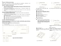
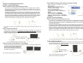
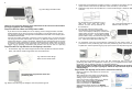
Monitor 1302 / 1501 User Manual GeChic Corporation 13F-4, No.367, Gongyi Road, West District, Taichung City 403 Taiwan (R.O.C.) Customer Service: [email protected] www.gechic.com Facebook Page : www.facebook.com/gechicen 1 Table of Contents Chapter 1 Content Descripon Chapter 1 Content Description P1 Secon 1 Noces for using On-Lap Monitor P2 Secon 2 Safety Instrucons P2 Secon 3 Safety Precauons P2 Secon 4 Product Maintenance P2 Secon 5 LCD Pixel Statement P2 Secon 6 On-Lap Monitor and Accessories P2 Chapter 2 Installaon Instrucons P4 Secon 1 Horizontal Display P4 Secon 2 Vercal Display P5 Secon 3 Upward Extension Display P6 Secon 4 Dual Monitor Display P7 Secon 5 Remove On-Lap Monitor’s Holder Plate P10 Chapter 3 Power On and Off the On-Lap Monitor Section 1 Notices for using On-Lap Monitor 1. The cable may be damaged if you pull it out by force. Please push forward the protruding part between the video and power cable connector and the back cover of the monitor to get out the connector by finger p. Fig.: Push out the connector using the finger p. 2. Noce when installing the On-Lap Monitor onto your laptop: ● When using On-Lap, flip open On- Lap to a horizontal posion first, and then open the laptop’s monitor. Avoid knocking against objects on the table. ● As shown below, it is recommend- ed to rotate the On-Lap Monitor to an orientaon viewable to the user (i.e., angle between 180° 225°) P11 Secon 1 Operang Instrucons P11 Secon 2 Monitor Display Se,ng P11 Chapter 4 Using with other 3C Products P15 Chapter 5 Hot Keys and OSD Instrucons Secon 1 Hot Keys Descripon Secon 2 OSD Descripon P16 ● The laptop’s monitor should be P16 Secon 3 Other Funcons of OSD P19 posioned in an upright posion to prevent it from ppling. If the laptop’s monitor lts, it means the laptop might not be able to sustain the weight. Chapter 6 Specificaon Secon 1 Plug and Play Forbidden: do not unplug by pulling the cord. P16 ● Keep the laptop away from the table edge to prevent it from falling off the table if it topples. P20 P20 Secon 2 Pin Assignment P20 Secon 3 Standard Default Modes P21 Secon 4 Troubleshoong P21 ● Use the laptop and On-Lap Monitor on a level table. If the table is not level, the laptop and On-Lap Monitor may topple. 3. On-Lap only reads DVI digital video signal; it does not support complete HDMI interface and does not have a speaker. 2 3 Section 2 Safety Instructions Please read this Manual carefully and observe the operaon instrucons and precauonary notes. Do retain this document for future reference. Section 3 Safety Precautions 1. The Product may be severely damaged from overturning or falling. Please do not place on a shaky or unstable table, cupboard or trolley. Do not use the On-Lap Monitor on a moving vehicle. 2. Do not place the Product on a vibrang surface as connuous vibraon may damage the internal components. 3. The Product is not waterproof. Do not use the Product at or near a place with water. 4. Do not insert any object into the Product’s slots or gaps. Section 4 Product Maintenance 1. Do not aDempt to repair the Product yourself. Please send it to our professional maintenance personnel for service. 2. Should any of the following condions occur, please contact our maintenance personnel for service: ● Unable to operate the Product aEer following the instrucons in the Manual. ● The Product falls and the outer casing is damaged. ● Power cable or video cable is damaged, worn or torn. ● Liquid infiltrated into the Product. ● Connect one end of the Mini Display- Section 5 LCD Pixel Statement The On-Lap Monitor uses a high quality LCD panel. Nevertheless, there might be instances where defecve pixels may occur; however, this will not affect the normal funconing of the Product. Section 6 On-Lap Monitor and Accessories 1. Parts Descripon: Fig.: Front parts descripon of On-Lap Fig.: Digital video and USB power cable Fig.: Analog video and USB power cable Package Contents ● On-Lap Monitor x1 ● Digital video and USB power cable x1 ● Analog video and USB power cable x1 ● Cable clip x1 ● Holder Plate x1 ● Double-sided adhesive tape x6 ● Non-woven bag x1 ● Quick Installaon Guide x1 ● User Manual x1 3. Oponal Accessories 2. Port and USB power cable to the video and power input port of the OnLap; and connect the other end to USB power output and DisplayPort of the laptop. Fig.: Back parts descripon of On-Lap Fig.: Mini DisplayPort and USB power cable ● Stand Bricks I ● Stand Bricks II Portable stands that can support the Portable and versale stands that can horizontal and vercal display of On-Lap support the horizontal, vercal and upward extension display of On-Lap Monitor. Monitor. LeE:: Front side of the Holder Plate Right: Back side of the Holder Plate Fig.: Stand Bricks I Fig.: Stand Bricks II 4 5 Chapter 2 Installation Instructions Section 1 Horizontal Display Step1. Install the video and USB power cable If you wish to use the HDMI port on the laptop, please use Digital Video and USBPowered Cable. If you wish to use the D-sub (VGA) or mini-Display Port on the laptop, please purchase the Analog Video and USB-Powered Cable or mini-Display Port and USB-Powered Cable. Connect the Image and Power connector to On-Lap video port, (1) Insert the latch into the groove of the video power connector. (2) Slide the video power connector toward the leE for a proper connecon. [Warning: Not inserng the latch into the groove may result in damage to connector. Please check the video power connector is properly connected and not protruding out. If protrusion occurs, the connecon might not be properly connected and monitor will not be able to operate.] Picture: Insert the latch into the groove of the video power connector. Step4. Make the laptop and monitor extension setting (Refer to Secon 2 of Chapter 3 for monitor display se,ng.) AEer powering on the laptop, go to Windows’ "Control Panel" to make the monitor extension se,ng. If you are using Windows 7: Select "2.DVI LCD" (digital video) or “2. display device: VGA” (analog video) for Display. Select "1366x768" for Resoluon Select "Landscape" for Orientaon Select "Extend these displays" for Mulple monitors, and drag Display 2 to the right side of Display 1. Section 2 Vertical Display Step1. Install the video and USB power cable Fig.: Insert the latch into the groove of the video power connector of the On-Lap Monitor Step2. Install Stand Bricks As illustrated, buckle the narrow opening [9 mm wide] of Stand Bricks to the leE and right sides of On-Lap Monitor. Be careful not to interfere with the cable. Adjust the posion of the Stand Bricks along the edge of the On-Lap Monitor to change the angle between the Monitor and the table. If you wish to use the HDMI port on the laptop, please use Digital Video and USBPowered Cable. If you wish to use the D-sub (VGA) or mini-Display Port on the laptop, please purchase the Analog Video and USB-Powered Cable or mini-Display Port and USB-Powered Cable. Connect the Image and Power connector to On-Lap video port, (1) Insert the latch into the groove of the video power connector. (2) Slide the video power connector toward the leE for a proper connecon. [Warning: Not inserng the latch into the groove may result in damage to connector. Please check the video power connector is properly connected and not protruding out. If protrusion occurs, the connecon might not be properly connected and monitor will not be able to operate.] Picture: Insert the latch into the groove of the video power connector. Buckle the narrow opening to the On-Lap Monitor Fig.: Insert the video power connector to the video power port of On-Lap Monitor Step2. Install Stand Bricks Fig.: Install Stand Bricks to the leE and right sides of On-Lap Monitor Step3.Connect On-Lap Monitor to the laptop Connect the USB power connector to the laptop's USB port, and then the digital video connector to the laptop's HDMI video output port (If Analog video and USB power cable is used, connect the analog video connector to the laptop's D-sub port). Tidy the cables with cable clips. As illustrated, place the On-Lap Monitor on the table in the vercal posion. Buckle the narrow opening [9 mm wide] of Stand Bricks to the leE and right sides of On-Lap Monitor. Be careful not to squeeze the cable Buckle the narrow opening to the On-Lap Monitor Fig.: Horizontal display of On-Lap Monitor Fig.: Install Stand Brick to the leE and right sides of the standing On-Lap Monitor 6 7 Step3. Connect On-Lap Monitor to the laptop It is recommended that you place the vercal standing On-Lap Monitor to the right side of the laptop for a beDer viewing angle. As illustrated, connect the USB power connector to the laptop's USB port, and then the digital video connector to the laptop's HDMI video output port (If Analog video and USB power cable is used, connect the analog video connector to the laptop's D-sub port). Tidy the redundant cables with cable clips. Note: Viewing On-Lap Monitor from the le1 side is be2er,, viewing is poorer from the right side Fig.: Vercal display of On-Lap Monitor Step4.Make the laptop and monitor extension setting (Refer to Secon 2 of Chapter 3 for monitor display se,ng.) AEer switching on the laptop, go to Windows’ “Control Panel” to make the monitor extension se,ng. If you are using Windows 7: Select “2.DVI LCD” (digital video) or “2. display device: VGA” (analog video) for Display Select “1366x768” for Resoluon Select "Portrait (flipped)" for Orientaon Select "Extend these displays" for Mulple displays, and drag Display 2 to the right side of Display 1. Section 3 Upward Extension Display Step1. Install the video and USB power cable If you wish to use the HDMI port on the laptop, please use Digital Video and USBPowered Cable. If you wish to use the D-sub (VGA) or mini-Display Port on the laptop, please purchase the Analog Video and USB-Powered Cable or mini-Display Port and USB-Powered Cable. Connect the Image and Power connector to On-Lap video port, (1) Insert the latch into the groove of the video power connector. (2) Slide the video power connector toward the leE for a proper connecon. [Warning: Not inserng the latch into the groove may result in damage to connector. Please check the video power connector is properly connected and not protruding out. If protrusion occurs, the connecon might not be properly connected and monitor will not be able to operate.] Picture: Insert the latch into the groove of the video power connector. Fig.: Insert the video power connector to the video power port of On-Lap Monitor Step2. Install Stand Bricks As illustrated, place the On-Lap Monitor on Stand Bricks II. Note: Center the On-Lap Monitor for close fi,ng with Stand Bricks II. Fig.: Place On-Lap Monitor on Stand Bricks II. Step3. Connect On-Lap Monitor to the laptop Place the laptop in front of the On-Lap Monitor and align the upper side of the laptop to the lower display edge of the On-Lap Monitor. Connect the USB power connector to the laptop's USB port, and then connect the digital video connector to the laptop's HDMI video output port (If Analog video and USB power cable is used, connect the analog video connector to the laptop's D-sub port). Fig.: Upward extension display of On-Lap Monitor Step4.Make the laptop and monitor extension setting (Refer to Secon 2 of Chapter 3 for monitor display se,ng.) AEer switching on the laptop, go to Windows’ "Control Panel" to make the monitor extension se,ng. If you are using Windows 7: Select "2.DVI LCD" (digital video) or "2. display device: VGA" (analog video) for Display. Select "1366x768" for Resoluon Select "Landscape" for Orientaon Select "Extend these displays" for Mulple displays, and drag Display 2 to the top side of Display 1. Section 4 Dual Monitor Display [Note: Ultrabook or laptop of smaller size than On-Lap may not be suitable for this usage.] Step1. Install the Holder Plate to the back cover of the laptop’s monitor Open the shaE’s Hinge Plate of the On-Lap Monitor to 180° and place the On-Lap Monitor on the laptop's back cover. Peel off the other double-sided adhesive tape on the Holder Plate and aDach the Holder Plate to the laptop, as illustrated. Note: 1) Keep the Holder Plate 2mm from the edge of the laptop. 2) Align the On-Lap Monitor to the front edge of the laptop's back cover. 3) Keep the direcon of the Holder Plate the same as that of the shaE’s Hinge Plate 4) If the Holder Plate cannot securely aDach to the laptop because the laptop’s back cover has a protruding paDern or is anodized, use more double-sided adhesive tape as required. 5) Double-sided adhesive tape should be used on a horizontal surface; gently press on the adhesive tape aEer the Holder Plate is aDached. Leave for 2 hours before installing the On-Lap Monitor. 8 9 Fig.: Mounng the Holder Plate [Note: Do not reverse the direcon of the Holder Plate as this will reverse the direcon of the On-Lap Monitor a1er installaon.] Step2 Install the video and USB power cable If you wish to use the HDMI port on the laptop, please use Digital Video and USBPowered Cable. If you wish to use the D-sub (VGA) or mini-Display Port on the laptop, please purchase the Analog Video and USB-Powered Cable or mini-Display Port and USB-Powered Cable. Connect the Image and Power connector to On-Lap video port, (1) Insert the latch into the groove of the video power connector. (2) Slide the video power connector toward the leE for a proper connecon. [Warning: Not inserng the latch into the groove may result in damage to connector. Please check the video power connector is properly connected and not protruding out. If protrusion occurs, the connecon might not be properly connected and monitor will not be able to operate.] Step3 Install On-Lap Monitor to the laptop’s monitor 1. 2. Rotate the On-Lap Monitor clockwise so that it is parallel to the laptop, open the laptop monitor and the On-Lap Monitor at the same me, as illustrated. 3. Adjust the angle of the On-Lap Monitor. A recommended angle is between 180° and 225°. Fig.: Rotate the On-Lap Monitor to the right side, then open the laptop monitor and the On-Lap Monitor at the same me. Fig. A recommended angle is between 180° and 225°. 4. Connect the video and power cable As illustrated, connect the USB power connector to the laptop's USB port, and then the digital video connector to the laptop's HDMI video output port (If analog video and USB power cable is used, connect the analog video connector to the laptop's D-sub port). Tidy the redundant cables with cable clips. Fig.: Dual monitor display mode 5. As illustrated, move the On-Lap Monitor upward from the laptop’s back cover, press down on the posioning clip at the first posioning hole, and move the OnLap Monitor unl the posioning clip pops up from the second posioning hole. As illustrated, align the shaE’s Hinge Plate of the On-Lap Monitor with the Holder Plate, and slide the shaE’s Hinge Plate into the Holder Plate. Fig.: Slide the shaE’s Hinge Plate into the Holder Plate Fig.: Moving the posioning clip from the first posioning hole to the second posioning hole. AEer On-Lap Monitor moves up, it is no longer fixed to the boDom of the laptop, and the laptop’s monitor can be lted backward. [Note: If your laptop is smaller than On-Lap Monitor, the cable may get stuck when flipping the Monitor (see upper right figure). Follow the steps above to adjust the monitor height.] Step4.Make the laptop and monitor extension setting The posioning clip protrudes at the first posioning hole Fig.: Make the posioning clip wedge to the first posioning hole (Refer to Secon 2 of Chapter 3 for monitor display se,ng.) AEer switching on the laptop, go to Windows’ "Control Panel" to make the monitor extension se,ng. If you are using Windows 7: Select "2.DVI LCD" (digital video) or “2. display device: VGA” (analog video) for Display Select "1366x768" for Resoluon Select "Landscape" for Orientaon Select "Extend these displays" for Mulple displays, and drag Display 2 to the right side of Display 1. 10 11 Step5.Remove On-Lap Monitor from the laptop 1. Remove the On-Lap Monitor from the laptop. As illustrated, rotate clockwise and open the On-Lap Monitor, press down on the posioning clip, and pull forward the On-Lap Monitor along the Holder Plate to slide out the shaE’s Hinge Plate. Fig.: Press down on the posioning clip to slide out the shaE’s Hinge Plate from the Holder Plate. Chapter 3 Power On and Off the On-Lap Monitor Section 1 Operating Instructions 1. Inial use: when the On-Lap’s USB power cable is connected to a 5V DC power source, On-Lap will automacally switch on. 2. Switching on the On-Lap Monitor from an off mode: press “Power” to switch on the On-Lap Monitor. 3. Follow the steps below to proceed with the monitor display se,ng. 4. When On-Lap is on, you may press the “power” buDon to switch off On-Lap. Section 2 Monitor Display Setting 1. Set resoluon –Windows 7 system ● Click on Section 5 Remove On-Lap Monitor’s Holder Plate 1. Remove the On-Lap Monitor first 2. Insert a ruler or rigid flat arcle into the gap at boDom of the Holder Plate; gently and evenly apply force back and forth to make the doublesided adhesive tape lose its viscosity. Do not use metal objects that can easily scratch the surface. icon at the boDom leE of the screen, and a menu will be display. ● Click on Control Panel ● Click on Appearance and Personalizaon ● Click on Display>Connect to an external display [Note: Do not try to liE up the Holder Plate directly with hands as it may result in deformaon of the Holder Plate for reuse.] ● Normally Display 1 is the laptop’s monitor, Display 2 is the external monitor. Click on Detect if you are unsure. 12 13 ● At Display, select “2.DVI ● ● ● ● 2. LCD” (digital video) or “2. display device: VGA” (analog video) for Display Select "1366x768" for Resoluon Select "Landscape" or "Portrait" for Orientaon Select "Extend these displays" for Mulple display, and drag Display 2 to the right side of Display 1. For Duplicated mode, select "Duplicate these displays". Select OK and exit aEer saving the se,ngs. Resoluon se,ng– Windows XP system ● Click on ● Click on SeDng, select Monitor at Display, and set the Screen Resoluon as 1366x768; Select "Extend my Windows desktop to this monitor" and then select ”OK” and exit. [Note: "Vercal mode" cannot be directly chosen on Windows XP system; the adjustment needs to be made via the video card. Please refer to the user manual of your video card.] 3. Se,ng the MAC system [Note: Color LCD and DVI LCD must have the same color seDngs. This way the On-Lap Monitor and MacBook display quality can be closer to each other. This seDng requires the conversion cable from the Digital AV adaptor to HDMI connector to connect with the digital video cable of On-Lap ; or use the Mini DisplayPort- USB power cable available for purchase from GeChic.] Start ● Click on Se,ng > Control Panel ● Click on Appearance and Theme ● Click on System Preferences ● Click on Displays ● Click on Adjust screen resoluon ● The above window appears on the laptop’s monitor ● The above window appears on the On-Lap Monitor. Please adjust the resoluon. 14 15 Chapter 4 Using with other 3C Products ● Select the arrangement mode to adjust the display posion of the monitors; this is the dual monitor display mode (laptop’s monitor) ● This is the upward extension mode (laptop’s monitor) 4. Se,ng Mac Operang System with On-Lap screen for Display Effect To reduce the color difference between On-Lap and Mac operang system, suggest user can follow the instrucon to adjust se,ng to reach the best result. Se,ng the LCD screen of MacBook Pro and the color of DVI LCD needs to be the same. ● ● ● ● Select [Display] to set Mac Book Pro There are two LCD se,ngs, Mac display (color LCD) and On-Lap display (DVI LCD Two LCD se,ngs need to be the same (as shown) Go into OSD color adjustment- color temperature (refer to User Manual Page 16 Secon 4) ● Adjust R/G/B Red -> increase to 54 Green -> increase to 52 Blue -> increase to 53 Values above are suggested for reference only, user can base on preference to adjust values. If user’s digital camera, smartphone, or other devices support DVI output, then it can be used with On-Lap [Note: Actual result depends on product video signal output format and use, not all products can make On-Lap display full screen.] 1. Before using digital camera, please purchase 5V portable baDery, and HDMI to miniHDMI adapter. Connecon Method: On-Lap USB power connector to portable baDery, digital connecter to HDMI to mini-HDMI adapter, then connect to mini-HDMI port on digital camera. On-Lap resoluon is 1366x768, some digital camera will automacally make resoluon to 720x480 or less, resulng in object size displayed on On-Lap different from actual object size. It is suggested that user check the specificaon of digital camera before deciding to use with On-Lap. 2. Before using smartphone, please purchase USB portable baDery, and HDMI adapter for smartphone. Connecon Method: Connect smartphone with HDMI adapter, connect HDMI adapter to On-Lap digital connector, On-Lap USB power connector to portable baDery. [Note: Some smartphone or tablet only support HDMI output and does not support DVI output, thus is unable to use with On-Lap.] 3. Before using video player or game console, please purchase USB portable baDery Connecon Method: Connect On-Lap digital connector to video player or game console HDMI port. Connect the On-Lap USB power connector to portable baDery. Fig.: Connecon between On-Lap Monitor and digital camera, iPhone or iPad 16 17 Chapter 5 Hot Keys and OSD Instructions 3. Note: The hot keys are capacive sensing bu2ons which are acvated by gentle touching. Do not press too hard or too fast connuously. Repeated pressing of a bu2on will make the bu2on slow down in responding. For connuous adjustment of "Increase/ Up" or "Decrease/Down", press and hold the corresponding bu2on for automac connuous increase/decrease. Color Se,ng - Brightness to launch the OSD panel. ● Press ● Press or to select ● Press or to select Brightness sub-menu and press Section 1 Hot Keys Description , press to enter; press or to enter. to Power: press power switch to switch off power. proceed with brightness adjustment → adjust the Exit: when there is no OSD menu; pressing the exit buDon will acvate automac adjustment funcon (only pertains to analog video signal VGA). Menu/Select: press menu buDon to launch OSD panel. Increase brightness/move up: press to increase brightness; if the OSD menu is launched, pressing Press and hold for automac connuous increase. backlight from 0-100. Press ● Press to 4. will move up the list. Section 2 OSD Description ● Press or to view the funcons. To adjust a certain funcon, press exit. Color Se,ng – Color temperature adjustment ● Press buDon to launch the OSD panel. ● Press or to select ● Press or to select Color temperature , press adjustment sub-menu and press ● Press or to enter. to enter. to adjust color saturaon for R/G/B. Red → increase or decrease the “red” saturaon of the image Green → increase or decrease the “green” saturaon of the image Blue → increase or decrease the “blue” saturaon of the image to exit ● Press 1. Basic BuDons operaon buDon to launch the OSD panel. hold for automac connuous decrease. Decrease brightness/move down: press to reduce brightness; when the OSD menu is launched, press to move down the list. Press and hold for automac connuous decrease ● Press and to 5. Color Se,ng – Color Temperature launch it. If the selected funcon consists of sub-menu, press or again to view the sub-menu. When the desired funcon is highlighted, press ● Press or to launch it. to change the se,ngs. To exit, press preceding steps to adjust other se,ngs. to launch the OSD panel. ● Press or to select ● Press or to select Contrast sub-menu and , press or to enter. to proceed with the contrast adjustment → adjust the display contrast from 0-100. ● Press to exit. ● Press or ● Press to exit. Repeat the or menu, press ● Press or to select , press to enter. to select Color Temperature subto enter. to proceed with the adjustment. Cold color 9300K → Revert to cold color. ● Press to enter; press to launch the OSD panel. Warm color 6500K → Revert to warm color. 2. Color se,ng - Contrast press ● Press Custom → Revert to inial color temperature. ● Press to exit. 19 18 6. Image Adjustment: applicable only for VGA input signal ● Press to launch the OSD panel. ● Press or to select , press Section 3 Other functions of OSD Monitor State Displays GeChic protecon System is launched without digital or analog input source screen Scenario to enter. ● Press or to select the sub-menu, press to enter, press or to adjust Clock → Adjust the horizontal scan rate. If the rate is incorrectly set, the vercal lines on screen and screen width will not be properly displayed. Phase → Adjust the phase of pixel clock signal. If the posion is incorrectly adjusted and when the screen displays bright image, it will be affected by horizontal interference. Sharpness → Adjust the sharpness of the image. H Posion → Adjust the image’s horizontal posion. V Posion → Adjust the image’s vercal posion. ● Press to exit. System is launched but the video signal input source is incorrectly set in the OSD. The actual connected digital or All black; LED indicator is red analog input source differs from the se,ng. System is launched with digital or analog input source, and the video input source is correctly set in the OSD. Displaying input source; LED indicator is green System shuts down All black 1. Monitor State Explanaon ● When there is no analog or digital input source, the screen will display no signal. 7. Menu Adjustment ● Press to launch the OSD panel. ● Press or to select , press to enter. ● Press or to select sub-menu, press enter, press or to adjust. to 2. Low voltage protecon instrucon ● When a low voltage of 5V DC is connected (through USB power cable), OSD will display insufficient power indicator. within the me limit to ● You can press OST Timer → adjust OSD me Language → select language Reset → restore to factory se,ngs Version → factory version ● Press to exit. decrease the brightness to reduce the USB 8. Signal Selecon ● Press to launch the OSD panel. ● Press or load. ● When the USB load is reduced to within to select , press to enter. ● Press or to select sub-menu, press to enter, press or to select input source, which are: VGA → select analog signal as source of input DVI → select digital signal as source of input Auto Search → auto search for input signal ● Press to exit. the USB power specificaon, the insufficient power indicator on the OSD will disappear. ● If the USB load is not reduced within the me limit, the system will reduce the brightness to 50% in order to reduce the USB load. ● If the USB load is sll not reduced to within the USB power specificaon, the system will further reduce the brightness to 25% to reduce the USB load. 20 21 Chapter 6 Specification Section 3 Standard Default Modes Section 1 Plug and Play Display Mode The On-Lap Monitor conforms to VESA DDC standard and supports VESA DDC2. DDC2B is a bi-direconal data channel based on I2C protocol. The host can request EDID informaon over the DDC2B channel. The On-Lap Monitor is able to inform the host system of its identy, and depending on the level of DDC used, communicate addional informaon about its display capabilies. Section 2 Pin Assignment 1. Digital video connector Pinout Pin No. Section 4 Troubleshooting Fig.: Digital video connector (Connect to PC’s HDMI port) Name 1. Pin No. Name TMDS Clock Shield 1 TMDS Data2+ 11 2 TMDS Data2 Shield 12 3 TMDS Data2 13 Reserved 4 TMDS Data1+ 14 Reserved 5 TMDS Data1 Shield 15 SCL (I C Serial Clock for DDC) 6 TMDS Data1 16 SDA (I C Serial Data Line for DDC) 7 TMDS Data0+ 17 DDC Ground 8 TMDS Data0 Shield 18 +5 V Power 9 TMDS Data0 19 Hot Plug Detect 10 TMDS Clock+ TMDS Clock MAC 640x480 60 Hz 2 VESA 720x400 60 Hz 3 SVGA 800x600 56 Hz 4 SVGA 800x600 60 Hz 5 XGA 1024x768 60 Hz 6 WXGA 1366x768 60 Hz With Digital video cable Problem Screen Display Blank screen No screen image OSD shows “No Signal” warning 2. Resoluon 1 Soluon Please check if the video and USB power plug is correctly connected to the On-Lap Monitor’s video power port. Please check if USB power cable is connected to a 5V DC power source. Please adjust Brightness and Contrast se,ngs, or reset them to factory default via OSD. Please check if Digital video cable is correctly connected to On-Lap Monitor’s video input port and computer’s HDMI output port. With VGA cable Problem No screen image Screen Display Blank screen Pin No. Name Pin No. Name Pin No. Name Soluon Please check if the video power plug is correctly connected to the On-Lap Monitor’s video power port. Please check if USB power cable is connected to a 5V DC power source. 1 RED 6 RGND 11 NC Please adjust Brightness and Contrast se,ngs, or reset them to factory default via OSD. 2 2. VGA Connector Pinout GREEN 7 GGND 12 SDA 3 BLUE 8 BGND 13 HSYNC 4 NC 9 +5V 14 VSYNC GND 10 SGND 15 SCL 5 3. Fig.: VGA Connector (Connect to PC’s VGA port) USB Power Cable Connector Pinout Pin No. Name 1 Vcc(+5V) 2 NC 3 NC 4 Ground Fig.: USB Power Cable (Connect to 5V DC Power) Abnormal screen image 3. OSD displays “No signal” warning Please check if Digital video cable is correctly connected to On-Lap Monitor’s video input port and computer’s VGA output port. Image disappears or image size is too big, too small, or image is not centralized Please adjust resoluon, clock, horizontal posion and vercal posion via OSD. If your laptop does not have the opon of “Duplicate these displays”, “Extend these displays” or “portrait”, it could be limited by the graphics chip of the laptop, or the graphics chip funcon is limited by the laptop’s power saving mode, or the graphics chip driver needs an update. It is recommended that you seek technical support from your laptop manufacturer or graphics chip maker.