1
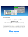
Broadcast Test System: R&S®SFU
R&S®SFU & R&S®WinIQSIMTM
Function and Uses
of the Arbitrary Waveform Generator (ARB)
Application Note
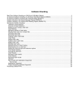
Arbitrary waveform generator – this term encapsulates the wide-ranging capabilities and applications that can
be provided by user-definable I/Q baseband signals and a vector signal generator. Rohde & Schwarz has developed the R&S®WinIQSIM TM software package specifically with this in mind. The first questions a user
might ask are: “How do the R&S ®SFU and R&S®WinIQSIMTM interwork and what features are available? This
Application Note has been produced to answer these questions.
Subject to change – H. Gsoedl 12.2006 - 7BM57_1E
®
®
R&S SFU + R&S WinIQSIM
Contents
1 Overview ...........................................................................................3
2 Requirements....................................................................................3
PC hardware requirements.............................................................3
PC software requirements ..............................................................4
R&S ®SFU requirements.................................................................4
3 Modulation........................................................................................5
Fundamentals................................ ................................ ...............5
Vector modulation.........................................................................6
Mathematical intermezzo..........................................................6
Phasor diagrams ......................................................................7
Vector modulator......................................................................8
4 R&S®SFU’s Arbitrary Waveform Generator...........................................9
R&S ®SFU-K35 circuit configuration.................................................9
ARB user interface...................................................................... 10
Data sheet values ....................................................................... 11
R&S ®SFU-K35 interpolating waveform generator ............................ 12
RAM ................................ ................................ ..................... 12
Interpolation ........................................................................... 13
Digital/analog conversion......................................................... 13
Lowpass filtering .................................................................... 14
Waveform file format .................................................................... 14
1st step: binary conversion...................................................... 14
2nd step: type, clock and samples tag................................ ..... 15
3rd step: waveform tag ............................................................ 15
5 R&S®WinIQSIM TM ............................................................................ 16
System! menu ............................................................................ 16
Block diagram ............................................................................ 17
Import ........................................................................................ 19
ARB menu ................................................................................. 20
6 Additional Applications for R&S®WinIQSIM TM ................................ ..... 22
R&S ®IQWizard ........................................................................... 22
Importing MATLAB files, ASCII files, etc................................... 22
Sampling............................................................................... 23
File export ................................ ................................ ............. 23
R&S ®NPR .................................................................................. 24
7 Application Example: R&S®WinIQSIM TM and R&S®SFU ...................... 25
GSM signal generation ................................................................ 25
*.WV file generation .................................................................... 26
Automatic transfer of the *.WV file to the R&S®SFU (I) ................... 29
Manual transfer of the *.WV file to the R&S ®SFU (II)....................... 29
Replaying the *.WV file on the R&S®SFU...................................... 34
8 References...................................................................................... 36
9 Additional Information....................................................................... 36
10 Ordering Information......................................................................... 37
7BM57_1E
2
Rohde & Schwarz
®
®
R&S SFU + R&S WinIQSIM
1 Overview
Arbitrary waveform generator – this term encapsulates the wide-ranging capabilities and applications that can be provided by user-definable I/Q baseband signals and a vector signal generator. Rohde & Schwarz has developed
the R&S®WinIQSIMTM software package specifically with this in mind.
But, how do the R&S ®SFU and R&S ®WinIQSIM TM interwork and what features are provided for the user? This Application Note provides the answers to
these questions .
This Application Note first outlines the fundamentals of analog and digital
modulation. The R&S ®SFU’s arbitrary waveform generator is then briefly described to lay the groundwork for the more extensive explanation of interworking with the R&S ®WinIQSIM TM package.
Note :
In this Application Note, the terms “arbitrary waveform generator”, “ARB generator” and “ARB ” are synonymous.
2 Requirements
The applications (R&S®WinIQSIM TM + additional applications) described in
this Application Note are based on the following requirements:
PC hardware requirements
Minimum
CPU
Pentium 133 MHz
Pentium II 450 MHz or later
RAM
32 Mbytes
128 Mbytes
Hard disk
10 Mbytes
50 Mbytes
Monitor
VGA monitor
(640 x 480)
SVGA color monitor, resolution 800 x 600 or later
Remote control
7BM57_1E
Recommended
IEC/IE EE bus interface:
National Instruments
adapters or compatible
alternatives
3
Rohde & Schwarz
®
®
R&S SFU + R&S WinIQSIM
PC software requirements
Minimum
Recommended
Operating system
Windows 95 / 98 / NT
4.0 / 2000 / Me / XP
Windows 98 / 2000 / Me / XP
Operating system
– expansions
---
Microsoft Internet Explorer
5.0 or later
IEC/IEEE bus driver:
NI-488.2 V 1.7 (or later)
Visa driver:
Remote control
NI-VISA V 3.0 (or later)
Visa remote control of
R&S devices:
RSIB-P ASSPORT V 1.4
Applications
---
R&S®WinIQSIM TM 4.3
See the Rohde & Schwarz website http://www.rohde-schwarz.com for information on R&S®WinIQSIMTM installation, functionality and operation.
®
R&S SFU requirements
7BM57_1E
Hardware
options
MEMORY
EXTENSION 1
R&S® SFU-B3
2110.7447.02
Softwareoptions
ARB GENERATOR
R&S® SFU-K35
2110.7601.02
4
Rohde & Schwarz
®
®
R&S SFU + R&S WinIQSIM
3 Modulation
Fundamentals
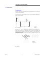
To make a signal carry information, three signal parameters can be varied as
a function of the information.
A sinusoid can be fully described in terms of the parameters amplitude A,
phase f and its period T:
f
A
A: Amplitude
T
Fig. 1: Sinusoid
T: Period
f: Phase offset
By varying A, f or T in a specific way, information can be impressed on a
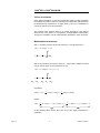
signal. This is referred to as amplitude, phase or frequency modulation depending on which parameter is varied. For example, a carrier signal c(t) is
amplitude-modulated with an input signal s(t) by multiplying these two signals together in a mixer:
s(t)
m(t)
c(t)
s(t): Input signal
c(t): Carrier
m(t): Modulated signal
Fig. 2: Mixer
7BM57_1E
5
Rohde & Schwarz
®
®
R&S SFU + R&S WinIQSIM
Vector modulation
When digital modulation is used, an orthogonality relation makes it possible
to maximize information content by allowing two independent data streams to
be simultaneously impressed on a single carrier. This form of modulation is
commonly referred to as I/Q modulation.
This method works because there is no mutual interference if two signals
which are 90° out of phase, i.e. in quadrature, undergo additive superposition.
This type of modulation can be mathematically described in steps as follows:
Mathematical intermezzo
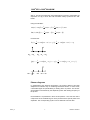
Step 1: Consider a single carrier with frequency
ω and phase angle ρ :
A(t ) = a ⋅ cos[ω ⋅ t + ρ ]
ω
Step 2: By introducing a frequency offset
ω n , trigonometric addition formulas
can be used to obtain a new expression for A(t):
A(t ) = a ⋅ cos[( ω 0 + ω n ) ⋅ t + ρ ]
ω0 − ωn
ω0 ω0 + ωn
the identity:
cos(α + β ) =
1
1
⋅ cos(α ) ⋅ cos( β ) − ⋅ sin( α ) ⋅ sin( β )
2
2
implies:
A(t ) =
1
1
⋅ a ⋅ cos( ωn ⋅ t + ρ ) ⋅ cos(ω0 ⋅ t ) − ⋅ a ⋅ sin( ωn ⋅ t + ρ ) ⋅ sin( ω0 ⋅ t )
2
2
Q
I
As the equation above shows, A(t) is the sum of two signal components in
quadrature.
7BM57_1E
6
Rohde & Schwarz
®
®
R&S SFU + R&S WinIQSIM
Step 3: The third and last step uses multiplication formulas to manipulate the
expression for A(t) to show that I/Q modulation always produces two sidebands:
Using the identities:
cos(α ) ⋅ cos( β ) =
1
1
cos(α − β ) + cos( α + β ) und
2
2
1
1
sin( α ) ⋅ sin( β ) = − cos(α − β ) + cos(α + β )
2
2
it follows that:
I (t) =
1
1
⋅ a ⋅ cos[( ω0 − ωn ) ⋅ t − ρ ] + ⋅ a ⋅ cos[(ω0 + ωn ) ⋅ t + ρ
2
2
ω0 − ωn
ω0 ω0 + ωn
Q (t ) = −
ω0 − ωn
1
1
⋅ a ⋅ cos[(ω 0 − ωn ) ⋅ t − ρ ] + ⋅ a ⋅ cos[( ω0 + ω n ) ⋅ t + ρ ]
2
2
ω0 ω0 + ωn
Phasor diagrams
In mathematics and electrical engineering, the phasor diagram has been
adopted as an effective way of visualizing sinusoidal carriers. In other words,
a sinusoidal signal is represented by a rotating vector or phasor. The sinusoidal oscillation is described by the amplitude, phase and rotating frequency of
the phasor.
I/Q modulation is represented in terms of two phasors . The sine and cosine
components of the oscillations give rise to phasors with a specific phase and
amplitude. The corresponding symbol can be deduced from this data.
7BM57_1E
7
Rohde & Schwarz
®
®
R&S SFU + R&S WinIQSIM
Fig. 3: Constellation diagram, I/Q modulation (COFDM/QPSK)
The figure above is a possible constellation diagram . The horizontal axis
represents the in-phase component and the vertical axis the quadrature component (90° phase shift) of the I/Q-modulated carrier.
Vector modulator
The following figure shows how an I/Q modulator could be implemented:
data(t): Data stream to be modulated
ARB
i(t): Data stream for in-phase component
q(t): Data
component
stream
for
quadrature
c(t): Carrier signal
iqmod(t): IQ-modulated signal
Fig. 4: I/Q modulator
i(t) and q(t) represent the two data streams that are transmitted independently of each other. They are generated from the original data (data(t)) by a
mapper. In the Q branch, the oscillator signal c(t) is phase-shifted by 90° before it is fed into the mixer; this is not the case in the I branch.
7BM57_1E
8
Rohde & Schwarz
®
®
R&S SFU + R&S WinIQSIM
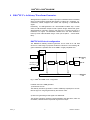
4 R&S ®SFU’s Arbitrary Waveform Generator
ARB generators operate on a different principle to hardware-based modulation,
which involves applying external data signals in realtime to a modulator, e.g.
scramblers, coders, mappers and mixers and outputting a modulated RF
signal:
Essentially, an ARB generator is an I/Q-modulation endless loop. In other
words, an I/Q-modulation sequence with a specific length, defined and generated beforehand, is stored in memory and read out in a continuous loop as a
baseband or IF signal. The baseband I/Q-data which has been obtained in
this way is then I/Q modulated using a mixer (see chapter 3 – Vector Modulator).
®
R&S SFU-K35 circuit configuration
The R&S®SFU’s arbitrary waveform generator can be used as an I/Q data
source for a wide range of purposes inside the instrument. The following diagram indicates the possible uses of the ARB in a highly simplified form:
Interferer
ARB
.
I/Q Analog
Out
…
I/Q Digital In
.
I/Q Analog In
.
Coder /
Mapper
.
Noise
Fading
D/A
I/Q
mod.
I/Q Digital
Out
MUX
Fig. 5: R&S ®SFU/ARB circuit configuration
Possible uses of the ARB generator:
1) Interference source:
The arbitrary waveform generator is used to additively superimpose an interference signal on a signal generated by the internal coder.
2) Source for generating an RF signal from ARB data:
The arbitrary waveform generator outputs baseband I/Q data which, after I/Q
modulation, determines the required RF signal at the output .
7BM57_1E
9
RF out
Rohde & Schwarz
®
®
R&S SFU + R&S WinIQSIM
The I/Q data from the arbitrary waveform generator can be fed to the analog or
digital I/Q output. The analog I/Q output is always activated (see graphics).
The digital output is configurable from the tap (tap after baseband impairments not shown).
See the User Manual for a more detailed description of the configuration options .
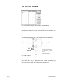
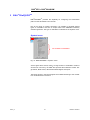
ARB user interface
The ARB function is implemented in the user interface of the R&S®SFU in the
following way:
After <APPL> on the R&S ®SFU is pressed, the ARB interface can be selected.
Fig. 6: Selecting the ARB application
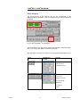
The ARB status, waveform file, clock rate, etc, can be selected using the following menu tree.
Fig. 7: ARB GUI
See chapt er 7 for a detailed example illustrating user prompting.
7BM57_1E
10
Rohde & Schwarz
®
®
R&S SFU + R&S WinIQSIM
Data sheet values
Fig. 8: Dat a sheet values
Different instrument generations may have different memory depths: More recent R&S®SFU-K35 options have memory depths of 128 Msamples rather
than 64 Msamples.
The option version can be determined with the “Setup-Hardkey” in
“HARDWARE OPTIONS”. If an “SFU-B3” option is listed, it is an ARB for sequence lengths of 128 Msamples.
Fig. 9: Hardware options
7BM57_1E
11
Rohde & Schwarz
®
®
R&S SFU + R&S WinIQSIM
R&S ®SFU-K35 interpolating waveform generator
The following figure shows how the R&S®SFU-K35 arbitrary waveform generator option functions:
RAM
Digital/analog
conversion
Interpolation
Lowpass filtering
fsample: Abtastrate
Fig. 10: Interpolating arbitrary waveform generator
The great advantage of the interpolating arbitrary waveform generator is that
short sequences can be “filled out” with interpolated values (
f sampl = 100 MHz)
to create long sequences. This makes it possible to significantly reduce any
aliasing products.
RAM
The information needed to generate waveforms is stored as a number of
samples in the random access memory (RAM). A sample is the amplitude of
a signal at a particular instant in time:
t/us
Fig. 11: Samples stored in RAM
The Nyquist-Shannon sampling theorem must be used to determine the
sampling frequency f sampl . This theorem states that the sampling rate
f sampl must be at least twice the frequency of the maximum frequency component in the signal
f max :
f sampl > 2 ⋅ f max
7BM57_1E
12
Rohde & Schwarz
®
®
R&S SFU + R&S WinIQSIM
Because of the interpolation filter (see section 4), the formula must be modified in the following way so that filtering does not cut out important regions of
the signal:
f sampl > 2 ⋅ f max / 0.31
The following applies for digital modulation:
f sampl > f symb ⋅ oversampli ng
where
f symb is the symbol rate.
Oversampling obeys the following inequality:
oversampling ≥
where
Bmod
f symb ⋅ 0.31
Bmod is the modulation bandwidth.
Using the sampling rate
ples
f sampl that has been obtained, the number of sam-
N can be determined as a function of the sequence duration t :
N = t ⋅ f sampl
Interpolation
The interpolation filter (fsampl = 100MHz) makes it possible to keep the nominal
sampling rate low. Plus, the number of aliasing products, should any occur,
is reduced:
t/us
t/us
t/us
Fig.12: Interpolation filter
Digital/a nalog conversion
The D/A converter weights the interpolated signals according to the formula
sin( f sampl )
f sampl
7BM57_1E
. The following signal is created in the time domain:
13
Rohde & Schwarz
®
®
R&S SFU + R&S WinIQSIM
t/us
Fig. 13: Signal after D/A conversion
Lowpass filtering
The last step, analog lowpass filtering, removes any remaining aliasing products:
t/us
Fig. 14: Output signal after lowpass filtering
Waveform file format
The R&S®SFU processes normalized, binary I/Q data which is contained in
specific tags. A tag comprises a name and a data packet, separated by a
colon and enclosed in curly braces. Example:
{Name: Data}
The following procedure must be used to generate waveforms manually:
1st step: binary conversion
To obtain binary data, normalized to -1 - +1 I/Q data from decimal numbers,
each decimal number is converted into an unsigned, 16-bit integer. This gives
a range, i.e. 65535, that is compatible with the resolution of the D/A converter.
The values which are obtained are then concatenated in the following way:
IQIQIQ…IQ.
7BM57_1E
14
Rohde & Schwarz
®
®
R&S SFU + R&S WinIQSIM
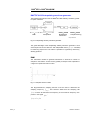
2nd step: type, clock and samples tag
The following lines are inserted before the actual binary data:
{TYPE: SFU-WV, xxxxxxx}
{CLOCK: yyy}
{SAMPLES: zzz}
xxxxxxx: Checksum which, however, is not checked by the R&S ®SFU and
so is set to: 0.
yyy: Clock frequency in Hz at which the waveform is output.
zzz: Number of samples.
The file that has been created now looks like this:
{TYPE: SFU-WV, 0}
{CLOCK: 10e6}
{SAMPLES: 20}
IQIQIQIQIQIQIQIQIQI ... IQ
3rd step: waveform tag
The last step is inserting the waveform tag which encloses the previously
mentioned I/Q data:
{WAVEFORM-Length: #IQIQIQIQIQIQIQIQIQI ... IQ}
The following entry is for 20 I/Q pairs (80 bytes). The tags which were mentioned previously must be inserted. There is also an optional COMMENT tag
which can be used to enter any comments the user wants to make.
{TYPE: SFU-WV,0}
{COMMENT: I/Q=sine/cosine, 20 points, clock 10 MHz}
{CLOCK: 10e6}
{SAMPLES: 20}
{WAVEFORM-81: #IQIQIQIQIQIQ ... IQ}
7BM57_1E
15
Rohde & Schwarz
®
®
R&S SFU + R&S WinIQSIM
5 R&S ®WinIQSIMTM
R&S ®WinIQSIMTM provides the capability for configuring the transmission
path from the transmitter to the receiver.
Due to the range of functions provided, it is possible to generate specific
types of modulation and then to output them to the R&S ®SFU’s arbitrary
waveform generator. The type of modulation is selected in the System! menu.
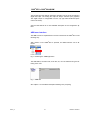
System! menu
Not available for R&S®SFU
Fig. 15: R&S®WinIQSIM TM: System! menu
As the figure above shows, there is a large number of modulation modes to
choose from. Ex factory, the R&S ®SFU provides the modulation modes: Single Carrier, Multi Carrier, Multi Carrier Mixed Signal and Import.
The blocks shown in the block diagram are modified according to the modulation mode selected in the menu.
7BM57_1E
16
Rohde & Schwarz
®
®
R&S SFU + R&S WinIQSIM
Block diagram
The blocks shown in the diagram are the key components of the
R&S ®WinIQSIMTM application. They are configured to generate the signal that
is required:
Fig. 16: R&S®WinIQSIM TM block diagram
The red sections in the figure above indicate the modulation dependent areas,
which can change with different modulation standards.
The table below overviews the functions of the modulation-independent blocks:
Block
Configuration
window
Function
- I/Q offset
- I/Q imbalance
- Quadrature error
Phase noise:
- VCO noise
- Reference noise
- PLL bandwidth
Sidebands :
- Frequency
- Level
7BM57_1E
17
Rohde & Schwarz
®
®
R&S SFU + R&S WinIQSIM
- Magnitude distortion
- Group delay distortion
- AM/AM conversion
- AM/PM conversion
Definition of power ramps
via:
- Ramp functions
- Ramp positions
Insertion
of
additional
propagation paths which
can be defined in the following ways:
- Path delay
- Level
- Phase
- Phase offset
- Frequency offset
The following interferers can
be additively superimposed
on the transmission path :
- Noise
- Unmodulated carrier
- Imported signal
7BM57_1E
18
Rohde & Schwarz
®
®
R&S SFU + R&S WinIQSIM
Receive filters can be set
via:
- Filter mode
- Filter function
- B*T
Quantization can be set via:
- I/Q resolution
- Coefficient resolution
Smoothing can be defined
via:
- Smoothing range
Generation of IF signals via:
- IF frequency
- I/Q polarization change
- Additional options
Import
To import user-specific I/Q modulations into R&S®WinIQSIM TM, the Import
selection option in the Systems! menu can be used to download I/Q data via
a TCP/IP connection from Rohde & Schwarz additional applications for
R&S ®WinIQSIMTM .
The following programs are available:
•
R&S®IQWizard (for importing I/Q data from MATLAB, spectrum analyzers, etc)
•
R&S®NPR (generation of noise signals)
Before a connection can be set up between one of the two applications and
R&S ®WinIQSIMTM , both the required additional application and the
R&S ®WinIQSIMTM must be started. TCP/IP data transmission cannot take
place unless the communications port is set both from the additional application and from R&S®WinIQSIM TM.
See the next chapter and the references to the Application Notes it contains
for a more detailed explanation of this and other functions.
When the import setting has been made on R&S ®WinIQSIM TM , two specific
configuration blocks are available for configuration:
7BM57_1E
19
Rohde & Schwarz
®
®
R&S SFU + R&S WinIQSIM
Block
Configuration window
Function
Configuring the network
client
in
®
TM
R&S WinIQSIM :
- Port number
- Time outs
Configuring the import
filter:
- Filter type / parameter
- Window function
- Pulse length
- Oversampling
- Baseband pulse
ARB menu
R&S ®WinIQSIMTM is a general tool for generating and transmitting I/Q signals.
The ARB data that has been generated must therefore be tailored to the ARB
generator that is used. This is done in the Target ARB Selection submenu:
Fig. 17: Target ARB Selection
The R&S®SFU-ARB cannot be operated unless “SFU-K35” has been selected.
The “Transmission…” menu item in the “SFU (ARB)” submenu must be selected to actually generate the ARB data:
I
II
III
IV
V
VI
VII
VIII
7BM57_1E
20
Rohde & Schwarz
®
®
R&S SFU + R&S WinIQSIM
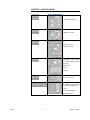
Fig. 18: Waveform Transmission
•
I: File comment
•
II: Currently selected simulation
•
III: Previously generated *.ibn file
•
IV: File browser for saving directly to the R&S®SFU
•
V: Name of the file to be saved locally
•
VI: Resetting the clock frequency
•
VII: Reversing the polarity of the I/Q modulation
•
VIII: With (IV), automatic waveform start after saving on the instrument
Items IV and VIII require R&S®SFU firmware version 1.40 .
See section 7 of this Application Note for an example illustrating the application.
With R&S ®WinIQSIMTM , the user of the R&S®SFU can automatically generate waveforms which are output in the endless loop mode in the ARB generator.
7BM57_1E
21
Rohde & Schwarz
®
®
R&S SFU + R&S WinIQSIM
6 Additional Applications for R&S ®WinIQSIM TM
®
R&S IQWizard
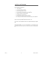
Fig. 19: R&S®IQWizard interface
R&S ®IQWizard provides the R&S ®SFU user with a wide range of functions for
loading I/Q data in many different formats or for recording I/Q data obtained
by sampling almost any signal waveform using a spectrum analyzer. The
data that has been read can then be saved in any file format or sent to
R&S®WinIQSIMTM via a TCP/IP connection.
For more information, see the Rohde & Schwarz Application Note
1MA28_13E[1] at http://www.rohde-schwarz.com.
Importing MATLAB files, ASCII files, etc
The following I/Q data types can be imported:
Fig. 20: Importable data types
7BM57_1E
22
Rohde & Schwarz
®
®
R&S SFU + R&S WinIQSIM
As indicated above, there is a choice of four different formats for importing
user-defined I/Q data from MATLAB. For an in-depth description of the syntax ,
consult the Application Note referred to above.
Sampling
When connected via an IEC/ IEEE interface, the R&S®FSIQ, R&S®FSP,
R&S ®FSU, R&S ®FSQ, R&S®FSL and R&S ®EXPI spectrum analyzers from
Rohde & Schwarz can be used for signal sampling under R&S ®IQWizard
control.
To find out how to determine the sampling rate and the number of samples,
see the chapter “R&S ®SFU’s Arbitrary Waveform Generator”.
Furthermore, it should be noted that the resolution bandwidth (RBW) of the
spectrum analyzer must at least equal the bandwidth of the signal to be recorded.
File export
The sampling procedure or the imported files can be exported with “Save IQ
Data”. The following target formats can be selected to do this:
Fig. 21: R&S®IQWizard: exportable data types
7BM57_1E
23
Rohde & Schwarz
®
®
R&S SFU + R&S WinIQSIM
R&S ®NPR
Fig. 22: R&S®NPR interface
When R&S ®Noise Power Ratio is directly connected to R&S ®WinIQSIM TM , it
is possible to generate noise power stimulus signals and, using other
Rohde & Schwarz instruments connected via the IEC/IEEE bus, to measure
the resulting noise power ratio of the DUT.
The test setup to be used is shown below:
Fig. 23: R&S®NPR test setup
For more information, see the Rohde & Schwarz Application Note
1MA29_4E[2] at http://www.rohde-schwarz.com.
7BM57_1E
24
Rohde & Schwarz
®
®
R&S SFU + R&S WinIQSIM
7 Application Example: R&S®WinIQSIMTM and R&S ®SFU
GSM signal generation
One of the examples supplied with WinIQSIM will be used as an illustrative
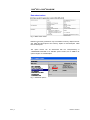
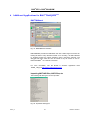
signal. Select “File – Open Settings”:
Fig. 24: Open Settings
In the window below, select the “\examples” directory in the applications
folder. Select “gsm_slo1.iqs”:
Fig. 25: Open dialog
The configuration for a GSM signal is now displayed in the block diagram .
7BM57_1E
25
Rohde & Schwarz
®
®
R&S SFU + R&S WinIQSIM
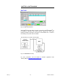
Fig. 26: Block diagram GSM signal
The simulation uses the following settings:
•
Data source: example file “GSM_TSC1.DBI” for midamble
modulation
•
Modulation type: MSK
•
Coding: GSM diff.
•
Symbol rate: 270.833330 kHz
•
Sequence length: 1250 symbols
Filter/Windowing:
•
Filter: Gauss
•
B*T: 0.30
•
Window function: Rect
•
Pulse length: 12
•
Oversampling: Auto
•
Baseband pulse: Rect
Power ramping (symbol/level): (0,-100), (155,0), (157,0), (305,-100),
(313,-100), 469,-100), (625,-100), (782, -100), (938, -100), (1094,-100)
*.WV file generation
To transfer the ARB data from R&S®WinIQSIM TM to the R&S ®SFU, the following procedure must be performed on R&S®WinIQSIM TM during the 1st step.
1.
ARB selection window
After clicking ARB in the main menu, the “Select Target ARB…” menu item
is used to select the arbitrary waveform generator:
7BM57_1E
26
Rohde & Schwarz
®
®
R&S SFU + R&S WinIQSIM
Fig. 27: ARB menu
2.
R&S ®SFU-K35 selection
Go to Target ARB and select the R&S ®SFU option “SFU-K35”. Confirm with
OK.
Fig. 28: Target ARB Selection
3. ARB transmission window
Click the ARB area in the main menu so that the submenu items SFU (ARB)
and then Transmission can be selected.
Fig. 29: ARB menu: “Transmission…”
4.
ARB transfer specification
To start the generation of an *.WV file for the current R&S®WinIQSIMTM project, “Source” must be selected in “Internal (Win IQSIM)”.
If the file that has been created is to be saved, the storage location must be
specified under “Destination” in the “File” or “SFU” menu item .
Note: The “SFU” option in the “Destination” area is available only if the n
istrument firmware version is 1.40 or later.
To create the ARB file, click Transmit.
7BM57_1E
27
Rohde & Schwarz
®
®
R&S SFU + R&S WinIQSIM
I
II
Fig. 30: SFU Waveform Transmission
7BM57_1E
28
Rohde & Schwarz
®
®
R&S SFU + R&S WinIQSIM
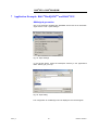
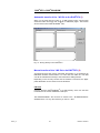
Automatic transfer of the *.WV file to the R&S®SFU (I)
When you click the text box under (I), a data browser opens. This browser
shows the folder structures and contents of R&S ®SFU pages. The browser
can be used to save R&S®WinIQSIMTM files .
Fig. 31: Saving directly to the R&S®SFU
®
Manual transfer of the *.WV file to the R&S SFU (II)
As mentioned some way above, automatic file transfer is not supported by
R&S ®SFU firmware versions below 1.40. This does not matter as *.WV files
can still be transferred manually to the instrument’s ARB generator.
Depending on the security context and the network environment, the appropriate alternative can be chosen from the list below.
USB stick
Copy the file from R&S®WinIQSIM TM to a USB memory stick. Use the stick
to transfer the file via the R&S®SFU’s USB port.
The R&S®WinIQSIMTM file can then be saved to the “D:\ARB\Waveforms”
standard folder or to any other directory on the “D:\” drive.
7BM57_1E
29
Rohde & Schwarz
®
®
R&S SFU + R&S WinIQSIM
FTP
An FTP server is installed as standard on the R&S ®SFU. It can be started by
entering “c:\program files\a-ftp”. The FTP server can also be used to transfer
the file created by R&S®WinIQSIM TM. The FTP client of the DOS command
line is used for this example for reasons of availability.
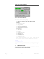
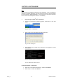
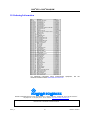
Determining the R&S®SFU’s IP address
1.
•
Under the instrument’s operating system, select “Run” in the start
menu.
Fig. 32: "Run..." start menu
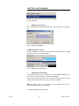
•
Enter “cmd” in the entry field and confirm with “OK”.
Fig. 33: Run dialog box
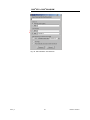
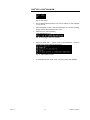
•
Enter “ipconfig” in the DOS entry mask which now appears. Confirm
with ENTER.
Fig. 34: Displaying the IP address
The IP address is outlined in red.
2. FTP connection on the client
7BM57_1E
•
Enter “ftp” in the DOS command line. Confirm with ENTER.
•
Enter “open”. Confirm with ENTER.
30
Rohde & Schwarz
®
®
R&S SFU + R&S WinIQSIM
Fig. 35: FTP client
•
The IP address obtained above can now be entered. In this example:
10.113.10.193
•
When prompted to enter a user and password, do not enter anything;
simply confirm with ENTER in each case.
•
Select the FTP server directory:
“cd d:\ARB\Waveforms”
Fig. 36: Changing to the FTP directory
•
When you enter “put” + <name of file to be transferred> , the file is
copied to the current R&S®SFU directory .
Fig. 37: File transfer via FTP
•
7BM57_1E
To terminate the FTP client, enter “quit” and confirm with ENTER.
31
Rohde & Schwarz
®
®
R&S SFU + R&S WinIQSIM
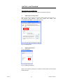
Shared folders on the R&S ®SFU
Alternatively, a folder or drive can be shared via Windows sharing.
1.
Opening the sharing menu
Right mouse click the folder to be shared. Select “Sharing and Security”. In
the window that appears, click the “Share this folder” item
(“D:\ARB\WAVEFORMS”) in the “Sharing” index:
Fig. 38: Sharing menu
2.
Setting permissions
Go to “Permissions”.
Fig. 39: Setting permissions
Select “Full Control” for “Everyone”. Close the current window and the sharing
window with OK.
7BM57_1E
32
Rohde & Schwarz
®
®
R&S SFU + R&S WinIQSIM
3.
Accessing shared directories
By entering “\\<IP address>\<Shared folder >”, this directory can be accessed from the computers in the network. Without the following user account/password, access will be denied:
User: “Instrument”
Password: “Instrument”
7BM57_1E
33
Rohde & Schwarz
®
®
R&S SFU + R&S WinIQSIM
Replaying the *.WV file on the R&S ®SFU
1.
ARB selection window
The ARB interface can be selected by pressing <APPL> on the R&S®SFU .
Fig. 40: Selecting the ARB application
2.
ARB settings
Set the ARB to “ON”. Then click “LOAD WAVEFORM”.
Fig. 41: ARB menu
3.
Selecting the *.WV file
Select the directory you want and then the file you require. Confirm your selection.
Fig. 42: Loading the waveform
4.
Changing to the TX interface
By pressing <APPL> on the R&S ®SFU, select the “TX” application.
Fig. 43: TX application
7BM57_1E
34
Rohde & Schwarz
®
®
R&S SFU + R&S WinIQSIM
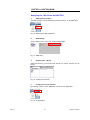
5. Selecting the ARB generator as a signal source
Under “SIGNAL SOURCE”, select “ARB”. The ARB signal is then output with
modulation on.
Fig. 44: Signal source selection
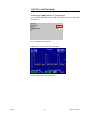
A GSM signal is now output at the RF output:
Fig. 45: GSM signal in the time domain
7BM57_1E
35
Rohde & Schwarz
®
®
R&S SFU + R&S WinIQSIM
8 References
[1]
Gerlach, Ottmar (2005). Application Note 1MA28_13E. I/Q Wizard.
I/Q Signal Measurement & Conversion. Munich: Rohde & Schwarz
GmbH & Co. KG website: http://www.rohde-schwarz.com.
[2]
Gerlach, Ottmar (2001). Application Note 1MA29_4E. NPR – Noise
Power Ratio. Signal Generation and Measurement. Munich: Rohde &
Schwarz GmbH & Co. KG website: http://www.rohde-schwarz.com.
9 Additional Information
Our Application Note are regularly revised and updated. Check for any
changes at http://www.rohde-schwarz.com.
Please send any comments or suggestions about this Application Note to
7BM57_1E
36
Rohde & Schwarz
®
®
R&S SFU + R&S WinIQSIM
10 Ordering Information
For additional information about measurement
Rohde & Schwarz website www.rohde-schwarz.com
equipment,
see
the
ROHDE & SCHWARZ GmbH & Co. KG . Mühldorfstraße 15 . D-81671 München . Postfach 80 14 69 . D-81614 München .
Tel (089) 4129 -0 . Fax (089) 4129 - 13777 . Internet: http://www.rohde -schwarz.com
This Application Note and the supplied programs may only be used subject to the conditions of use set forth in the
download area of the Rohde & Schwarz website.
7BM57_1E
37
Rohde & Schwarz