1
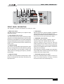
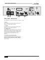
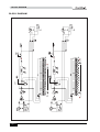
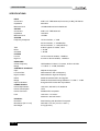
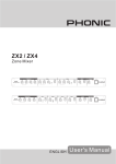
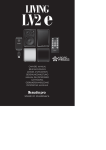
$
6835$&859(
(1*/,6+
SupraCurve
A6600
TABLE OF CONTENTS
INTRODUCTION ................................4
FEATURES ........................................4
GETTING STARTED..........................4
FRONT PANEL DESCRIPTION.......5
REAR PANEL DESCRIPTION.........6
TYPICAL GRAPHIC EQUALIZER
OPERATION ......................................7
BLOCK DIAGRAM............................8
DIMENSIONS.....................................9
SPECIFICATIONS............................10
APPENDIX .......................................11
INTRODUCTION / FEATURES / GETTING STARTED
INTRODUCTION
GETTING STARTED
Congratulations on your purchase of the A6600
SUPERCURVE, a dual 31-band graphic equalizer. In
order to get the best performance from your A6600
SUPERCURVE, please read this user’ s manual
carefully and keep it for future reference.
●30mm
sound system with care, and do not share sockets or
grounding with light dimmers.
balanced lines wherever possible. If feasible, cross
low noise, high-quality performance
audio and lighting cables at right angles to minimize
the possibility of interference. Keep unbalanced
cables as short as possible.
VR for precise adjustment
●Switchable
The unit must be properly grounded to avoid electrical
shock to the operator. Choose the main supply for the
2 Separate audio cables from dimmer wiring, using
FEATURES
●Extremely
1 Check the AC voltage before connecting the plug.
boost/cut range: 6dB and 12dB
3 Check your cables regularly and label each end for
easy identification.
●EQ
IN/OUT switch
●Center-dented
●Illuminated
●+/-15dB
4 Before switching on the main power, set the input
level control to its minimum setting. Doing so will
sliders
prevent excessive noise caused by bad level
adjustment, faulty wiring, defective cables, or bad
connections.
buttons and faders
input gain range for easy level matching
5 Always turn the unit on before turning on the
●
8-segment LED input level display with CLIP
warning
●Dual
variable 15Hz to 400Hz LOW CUT filter and
2.5KHz to 30KHz HIGH CUT filter
●Auto
relay-controlled bypass
●Balanced
●1/4"
power amplifier; always turn it off after turning off the
amplifier.
6 Always turn off the main power before connecting or
disconnecting the unit.
7 Never use solvents to clean the unit. Clean the unit
with a soft, dry cloth.
inputs and outputs
TRS and XLR connectors
●Shielded
toroidal power transformer for low noise
interference
Page 4
A6600 USER’S MANUAL
PHONIC CORPORATION
FRONT PANEL DESCRIPTION
3
1
2
-24 -18 -12 -6
1
4 5 6
0
+6
12 CLIP
+12/+6
0
FILTER
RANGE
20
-24 -18 -12 -6
2
-12/-6
0
+6
A6600
+15
0
-12/-6
25
31.5
40
50
63
12.5K
16K
20K
12 CLIP
EQ IN
+12/+6
SupraCurve
12dB
6dB
INPUT
+12/+6
EQ IN
0 dB
-15
7
+12/+6
0 dB
12dB
6dB
0
0
-12/-6
-15
+15
INPUT
FILTER
-12/-6
RANGE
FRONT PANEL DESCRIPTION
The operations of channel 1 & channel 2 are exactly the same.
1 INPUT level control
The INPUT level control allows you to adjust the input
signal level (volume).
2 LEVEL METER with CLIP LED
The LEVEL METER provides instant monitoring of output
signal level. To avoid possible distortion, reduce the input
level if the CLIP LED lights up. For the LED to blink briefly
5 EQ IN button
Depress this button to activate the A6600; it will light up
yellow. Release it to terminate all A6600 functions,
providing an immediate comparison between the original
sound and the sound as processed by the A6600.
6 EQ RANGE selector button
One benefit of using a graphic equalizer is that the
during the loudest parts of your program is acceptable; if
it stays on for several seconds, however, distortion may
frequency sliders form a graphic depiction of the
frequency response curve you have set. When the
begin to occur.
setting requirements are subtle, however, it may not be
easy to identify the curve. If you encounter this difficulty,
depress the EQ RANGE selector switch to increase the
range of the level settings.
3 LOW CUT FILTER
The LOW CUT FILTER allows high frequencies to pass
through unchanged while severely attenuating (cutting)
very low frequencies. Use this switch to protect your
audio system from damaging low-frequency transients
(loud thumps).
When depressed, the button will light up red and set the
range at 6dB. When released, the same button will light
up green and set the range at 12dB.
4 HIGH CUT FILTER
The HIGH CUT FILTER allows low frequencies to pass
through unchanged while effectively attenuating very
high frequencies.
7 Illuminated frequency level slider
Moving the illuminated slider upward increases the
level of the related frequency; moving it downward
decreases the level of the related frequency.
PHONIC CORPORATION
A6600 USER’S MANUAL
Page 5
REAR PANEL DESCRIPTION
JACK CONFIGURATIONS
FOR INPUT JACKS
POWER
UNBALANCED
(+) ( - )
THE RISK OF
OT EXPOSE
OISTURE.
BALANCED
CH2
100~120V AC
FUSE 500 mA
~100V AC 60Hz
~120V AC 60Hz
~230V AC 50Hz
~240V AC 50Hz
OUTPUT
(BALANCED)
XLR-ASSIGN
INPUT
(BALANCED)
2
10
1
3
220~240V AC
FUSE T315m A
11
CTRIQUE
(G)
INPUT
9
1: GND
2:
+
3:
-
PUT
ANCED)
1
2
3
OUTPUT
8
REAR PANEL DESCRIPTION
The operations of channel 1 & channel 2 are exactly the same.
8 INPUT
Each channel has an XLR male connector and a
balanced 1/4" jack for input connection.
9 OUTPUT
Each channel has an XLR female connector and a
balanced 1/4" jack for output connection.
10 POWER switch
Use this switch to turn the A6600 on and off. Turn the
A6600 on before turning on the power amplifier; doing
so will prevent loud transients which can damage your
speakers and create noises unpleasant for your
audience.
11 AC power socket with fuse holder
Connect the supplied AC power cord to this socket, then
insert the plug into a wall socket of suitable voltage. A
blown fuse may be replaced only by a fuse of identical
type and rating.
Page 6
A6600 USER’S MANUAL
PHONIC CORPORATION
TYPICAL GRAPHIC EQUALIZER OPERATION
MIXER CHANNEL EQUALIZATION
TYPICAL GRAPHIC EQUALIZER
OPERATION
Many mixers provide only simple equalization for
individual channels. If your mixer has channel inserts,
you can patch your equalizer into a channel that is
being used for something important and use it to tailor
GENERAL TONE CONTROL
The graphic equalizer is a useful device for general tone
shaping because it is simple and easy to adjust. The
visual reference provided by the slide fader position
gives an approximate idea of the frequency response
generated: higher frequencies appear on the right, lower
frequencies on the left. To use the equalizer, you must
know the numerical frequency range of the tone you
wish to produce.
Here is a frequency range chart for your reference -- it is
a useful tool when first using a graphic equalizer. Use the
range chart as a guide, then adjust by ear. Unfortunately,
even a good equalizer cannot offer a complete solution
when a room has severe inherent acoustic problems.
Nor can equalization overcome the lack of sound clarity
caused by rooms with unduly long reverberation times.
FEEDBACK CONTROL
In live performance applications, graphic equalization
is almost always applied separately to the stage
the sound of this channel exactly as you want.
LARGE ROOM EQUALIZATION
Large rooms tend to suffer from multiple reflections with
long time delays and long reverberation intervals -factors which lead to reduced intelligibility and a
generally muddy sound. As sound travels long distances,
high frequencies attenuate more than low frequencies. In
general, a large room benefits from some low frequency
roll-off and some high frequency boost. Therefore,
reducing the low frequency output may be advantageous
in buildings made of concrete or stone, where much of
the bass is reflected rather than absorbed. Rolling off the
high frequency end above 5kHz may also contribute to
a more natural sound. The shape of the optimal house
curve varies according to the individual sound system
and acoustic environment; a degree of experience is
indispensible to achieving the best result.
monitor or foldback system to reduce the level of those
frequencies that would otherwise cause feedback
problems. These problems arise from monitor
positioning, sound reflected from the stage walls, and
peaks in the frequency response curves of the
monitor speaker system. A graphic equalizer can
provide some control over moderate feedback
problems, but it hasn't enough flexibility or resolution to
remedy a severe feedback response. The best results
are achieved by eliminating feedback points. One or
two feedback points can be eliminated by adjusting
the slide faders, but no more than 6dB should be cut.
If you find feedback points covering many equalizer
bands and cutting every affected band does not help,
you must reduce the system gain. The combined use
of a graphic equalizer for tone control and a parametric
equalizer for feedback control is highly recommended.
PHONIC CORPORATION
A6600 USER’S MANUAL
Page 7
Page 8
1
A6600 USER’S MANUAL
1
CH2 INPUT
2
CH2 INPUT
CH1 INPUT
2
CH1 INPUT
3
3
+15V
BUFFER
BUFFER
20
20
BOOST
DR
CUT
+15V
BOOST
DR
CUT
25
25
40
31
40
INPUT
AMP
31
INPUT
AMP
50
50
63
63
80
80
100
100
125
125
200
250
315
400
160
200
+6DB
+12DB
315
630
400
500
630
EQ2 OF VR LED 1*31
250
500
6/12dB LED
EQ1 OF VR LED 1*31
160
+6DB
+12DB
6DB LED
1K
800
1K
EQ2
800
EQ1
1.6K
2K
2.5K
1.25K
1.6K
HIGH CUT
2K
2.5K
3.15K
LOW CUT
3.15K
LOW CUT
HIGH CUT AND
LOW CUT
1.25K
HIGH CUT
HIGH CUT AND
LOW CUT
4K
4K
5K
5K
6.3K
-15V
6.3K
8K
8K
10K
10K
12.5K
12.5K
-15V
16K
16K
20K
20K
ON
ON
EQ IN2
EQ LED
EQ IN1
EQ LED
CH2_LED
CH1_LED
RELAY2
RELAY1
CH2 OUT
2
CH1 OUT
2
1
1
CH2 OUT
3
CH1 OUT
3
BLOCK DIAGRAM
BLOCK DIAGRAM
PHONIC CORPORATION
DIMENSIONS
PP
DIMENSIONS
PP
PP
PHONIC CORPORATION
A6600 USER’S MANUAL
Page 9
SPECIFICATIONS
SPECIFICATIONS
INPUT
Connectors
Impedance
XLR & 1/4" TRS balanced, line level (+4 dBu), RF filtered
56k ohms
Maximum level
OUTPUT
+24 dBu balanced and unbalanced
Connectors
Impedance
XLR & 1/4" TRS balanced
100 ohms
Maximum level
+24 dBu
SYSTEM
Frequency Response
10 Hz to 35 kHz, +/- 3 dB
20 Hz to 20 kHz, +/- 0.25dB (flat)
20 Hz to 20 kHz, +/- 1 dB (max/min)
THD
0.004% typical at +4 dBu, 1 kHz
Noise
Crosstalk
< -87 dB
< -80 dB
FILTERS
Low-cut
15 Hz to 400 Hz variable, -18 dB/oct
High-cut
EQUALIZER
Center Frequency
Range
CONTROLS & DISPLAY
Input
Low-Cut Filter
High-Cut Filter
EQ IN
Range
Input Level Meter
POWER SUPPLY
Power Requirement
Power Consumption
Power Connector
Fuse
PHYSICAL
Enclosure
Dimensions (W x H x D)
Net Weight
Page 10
2.5 kHz to 30 kHz variable, -18 dB/oct
ISO Standard 31-band, 1/3 octave, 20 Hz to 20 kHz
+/- 6 dB or +/- 12 dB, selectable
Adjusts the input gain
Determines the low-cut frequency
Determines the high-cut frequency
Switches between EQ in and bypass
Switches the boost/cut range between +/- 6 and +/- 12 dB
8-segment LED meter with clip indicator
100-120 V, 200-240 V, AC 50/60 Hz
15 W
Standard IEC receptacle
100-120 V: 1 A / 250 V
200-240 V: 500 mA / 250 V
Steel housing with aluminum front panel
483 x 88 x 151 mm (19 x 3.5 x 5.9 in.)
3.2 kg (6.9 lbs.)
A6600 USER’S MANUAL
PHONIC CORPORATION
APPENDIX
APPENDIX
Phonic recommends the following books for those
interested in advanced audio engineering and sound
system operation:
•
"Sound System Engineering" by Don and Carolyn
Davis, Focal Press, ISBN: 0-240-80305-1
•
"Sound Reinforcement Handbook" by Gary D.
Davis, Hal Leonard Publishing Corporation, ISBN:
0-88188-900-8
•
"Audio System Design and Installation" by Philip
Giddings, Focal Press, ISBN: 0-240-80286-1
•
"Practical Recording Techniques" by Bruce and
Jenny Bartlett, Focal Press, ISBN: 0-240-80306-X
•
"Modern Recording Techniques" by Huber &
Runstein, Focal Press, ISBN: 0-240-80308-6
•
"Sound Advice : The Musician’s Guide to the
Recording Studio" by Wayne Wadham, Schirmer
Books, ISBN: 0-02-872694-4-0
•
"Professional Microphone Techniques" by David
Mills Huber, Philip Williams. Hal Leonard Publishing
Corporation, ISBN: 0-87288-685-9
•
"Anatomy of a Home Studio: How Everything
Really Works, from Microphones to Midi" by Scott
Wilkinson, Steve Oppenheimer, Mark Isham. Mix
Books, ISBN: 091837121X
•
"Live Sound Reinforcement: A Comprehensive
Guide to P.A. and Music Reinforcement Systems and
Technology" by Scott Hunter Stark. Mix Books, ISBN:
0918371074
•
"Audiopro Home Recording Course Vol 1: A
Comprehensive Multimedia Audio Recording Text" by
Bill Gibson. Mix Books, ISBN: 0918371104
•
"Audiopro Home Recording Course Vol. 2: A
Comprehensive Multimedia Audio Recording Text" by
Bill Gibson. Mix Books, ISBN: 0918371201
PHONIC CORPORATION
A6600 USER’S MANUAL
Page 11