1
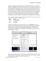
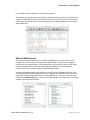
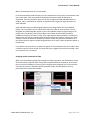
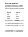
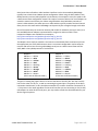
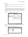
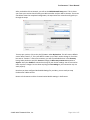
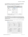
ProPresenter 5 User Manual ! Communication Module This module is only available for Mac OS X 10.6.8 and higher and requires ProPresenter 5.1.4 or higher. The CommunicaDon Module provides connecDvity to external devices via network or serial communicaDons according to what the protocol supports. The CommunicaDon Module consists of a number of different protocols which can be organized into three groups. This module supports the following: AMP, VDCP, Sony BVW, GVG100, Song BVS, RossTalk, DMX, and MIDI. Purchasing the CommunicaDon Module gives you access to any of these protocols. You can also choose to purchase MIDI as its own module. AVer you have purchased the CommunicaDon Module you will see the new CommunicaDon tab in Preferences. Note: A working knowledge of the protocol you need to use is strongly recommended as each protocol has various options available and they are not covered in great detail in this guide. Due to the variety of configurations for these protocols, we can’t offer much support. Protocol specifics should be available in product manuals or from hardware manufacturers. Playback Deck/Media Server Control Protocols These protocols include AMP, VDCP, and Sony BVW. AMP and VDCP are media server protocols that have more capabiliDes than Sony BVW such as triggering clips by name. BVW can only control the playback of an already triggered clip. Switcher Control Protocols These protocols include GVG100, Sony BVS, and RossTalk. These protocols can control a switcher, allowing you to remotely enable and disable keys or fade to black. Sony BVS is preferred over GVG100 when available since it has greater capabiliDes. © 2005-2012 Renewed Vision, Inc. Page 133 of 157 ProPresenter 5 User Manual ! RossTalk is a proprietary protocol supported by some Ross switchers. RossTalk is the preferred choice for a compaDble Ross switcher because it uses network communicaDon rather than serial. RossTalk is supported as 2 modes, Device and Controller. In Controller mode, ProPresenter can send commands to a connected Ross switcher. In Device mode, RossTalk provides some control of ProPresenter from a compaDble Ross switcher. For Device mode, the Ross switcher is setup to connect to ProPresenter as if it were an Expression CG machine. Once connected, Up/Down on the switcher will advance through the items of the selected playlist, and next will trigger slides or videos just like pressing the spacebar/right arrow key on the ProPresenter machine. Note that if you want to use both Controller and Device modes for RossTalk, you must configure 2 RossTalk devices, one for each mode as these modes require two different network connecDons. You can also clear the output using the Clear Layer command where the layers correspond to the different ProPresenter clear commands as follows: Layer 0 Clear All Layer 1 Clear Live Video Layer 2 Clear Background Layer 3 Clear Slide Layer 4 Clear Props To add any of the available protocols to ProPresenter, click on the Add Device buaon in the lower right corner and select the protocol from the list. Each protocol has unique configuraDon sebngs. We have set each protocol to use the standard configuraDon as specified by each manufacturer. If your configuraDon requires different sebngs you will need to refer to the documentaDon for the device you are connecDng to with ProPresenter. The screenshot below shows GVG100 as an example. AVer you have added a protocol, you will see a box that shows you the acDve protocols. You can connect or disconnect any protocol, or remove it, from here. If you need to change the sebngs for a protocol, click on the gear icon to open the sebngs menu. © 2005-2012 Renewed Vision, Inc. Page 134 of 157 ProPresenter 5 User Manual ! Click on Midi Setup or DMX Setup to modify these protocols. The following screenshot shows several of the protocols listed at the same Dme. ProPresenter is capable of supporDng more than one protocol at the same Dme, within reason. Some protocol combinaDons don't make sense to run at the same Dme, like AMP and VDCP, but some do like AMP and RossTalk. DMX and MIDI Protocols Both of these protocols allow the user to define the DMX channels or MIDI notes that are mapped to the various controls for ProPresenter. DMX is fixed to a sequence of conDguous channels just like a lighDng fixture, whereas MIDI allows you to map any note to a given MIDI controllable ProPresenter command. These sebngs are defined in the CommunicaDon preference pane in ProPresenter under the DMX and MIDI buaons. The DMX configuraDon allows you to define the starDng channel and displays how the other channels are mapped. DMX supports ArtNet over a network only. USB-‐DMX interfaces are not supported. The screenshots below show a standard DMX setup. These values are entered by clicking on the DMX Setup buaon in the CommunicaDon Module. The image below is a scrolling window, not two separate windows. © 2005-2012 Renewed Vision, Inc. Page 135 of 157 ProPresenter 5 User Manual ! MIDI is covered extensively in the next secDon. In the CommunicaDon preference pane you can setup devices which persist in ProPresenter unDl you remove them. They may opDonally automaDcally reconnect when ProPresenter is relaunched. From this preference pane you can also configure the DMX and MIDI opDons. In addiDon, there's a checkbox for whether to allow filenames longer than eight characters for VDCP and AMP. VDCP and AMP require a Video/Image Bin playlist to be designated as the Comm Module playlist. This is the playlist that is used to select clips with either of these protocols. You can designate any Video/Image Bin playlist as your Comm Module playlist by right-‐clicking on the playlist name. The display name of each video in this playlist must be unique and will be modified as necessary to make it unique. If the eight character filename opDon is checked, the display name will also be trimmed to eight unique characters as necessary. Consult your video switcher's manual to determine whether you need to enable the 8 character filename limit. If the switcher doesn't support variable length filenames, then you'll need to enable that opDon in ProPresenter. For a switcher control protocol, an opDon will appear in the contextual menu of any slide to add a switcher control cue to that slide. Any Dme that slide is triggered, the chosen command is sent to the switcher if it's connected. Assigning module commands to slides When you have enabled a protocol that supports sending commands, you will be able to assign those commands to specific slides. Each protocol supports different cue opDons, so the menu that you see will be different. If you only have a single protocol assigned, you will not have the sub-‐menu of protocols. GVG100, RossTalk (Controller mode), and Sony BVS are the only protocols that have slide cues available. © 2005-2012 Renewed Vision, Inc. Page 136 of 157 ProPresenter 5 User Manual ! Using RS-422 Serial with Communications Module RS-‐422 is a serial standard that defines how the serial signal is transmiaed electronically. There are several serial standards including RS-‐232 and RS-‐485. Note that these standards are electrically different and are not compaDble even though in many cases they use the same DB-‐9 connector. Unfortunately, there are different, incompaDble ways that RS-‐422 may be wired through a standard DB-‐9 connector. There are two common DB-‐9 pinouts that are used with RS-‐422 in the context of video producDon equipment. Depending on your computer serial interface, you may be required to create a cable or use adapters to convert from one pinout to another. In addiDon, you may have to compensate for a pinout on a serial interface that doesn't match either of these common pinouts. Here are the two common pinouts: Deck Control Slave DB-‐9, usually Female Pin 1 -‐> Ground Pin 2 -‐> Tx -‐ Pin 3 -‐> Rx + Pin 4 -‐> Ground Pin 5 -‐> Nothing Pin 6 -‐> Ground Pin 7 -‐> Tx + Pin 8 -‐> Rx -‐ Pin 9 -‐> Ground Deck Control Master DB-‐9, usually Male Pin 1 -‐> Ground Pin 2 -‐> Rx -‐ Pin 3 -‐> Tx + Pin 4 -‐> Ground Pin 5 -‐> Nothing Pin 6 -‐> Ground Pin 7 -‐> Rx + Pin 8 -‐> Tx -‐ Pin 9 -‐> Ground These pinouts were originally used on tape based playback decks and have since been used on media servers and video switchers as well. The Deck Control Master pinout would typically be found on a controlling device such as an editor or video switcher. The Deck Control Slave pinout would typically be found on a playback deck that is to be controlled via serial. There are two common types of RS-‐422 computer interfaces you might run into. One is the serial port on video hardware such as BlackMagic Decklink cards or Ultrastudio 3D devices. There are other similar devices such as those made by AJA which also have RS-‐422 ports, however we have discovered that AJA does not properly set their serial port configuraDon. In at least some of their devices (namely the ioXT), the serial port is fixed to a certain baud rate, parity, etc. and cannot be changed, as confirmed by AJA. Unfortunately, none of the manufacturers we talked to really support the serial port on their video hardware as a general purpose serial port, they tend to only support it when used with their own soVware. However, we found that the serial port on BlackMagic hardware was very reliable. The other common RS-‐422 interface is a simple RS-‐422/USB adapter. Note that this is not the same thing as (and not compaDble with) an RS-‐232/USB adapter which is much more common. RS-‐422/USB adapters are typically designed for use in compuDng environments rather than video producDon environments, therefore they will typically have a pinout that differs from the two specified above. In our limited tesDng, we have had mixed results with RS-‐422/USB adapters. There are also RS-‐422/RS-‐232 converters which may work in conjuncDon with a common RS-‐232/USB adapter. We have not tested this setup. © 2005-2012 Renewed Vision, Inc. Page 137 of 157 ProPresenter 5 User Manual ! Serial ports that are found on video hardware interfaces such as those made by BlackMagic typically have a Deck Control Master pinout configuraDon. When using the VDCP, AMP or Sony BVW protocols to control video playback in ProPresenter, the computer's serial port needs to be a Deck Control Slave configuraDon instead. This requires a custom cable or the use of adapters to switch the transmit and receive pins. When using GVG100 or Sony BVS editor protocols to control a video switcher, the editor port on a video switcher typically matches the Deck Control Slave pinout so this works with a BlackMagic serial port with just a straight through serial cable. One of the easiest ways to create the necessary DB-‐9 cable for whatever pinout you need, is to use two DB9/ethernet adapters connected with a straight thru ethernet cable. These inexpensive adapters are available from monoprice hap://www.monoprice.com/products/product.asp?p_id=1151 hap://www.monoprice.com/products/product.asp?p_id=1152 The adapters come ready to assemble. You insert the colored leads from the ethernet jack into the appropriate pins of the DB9 connector. Here is a common configuraDon used to swap the transmit and receive lines for using a BlackMagic serial port as a Deck Control Slave with the VDCP, AMP or Sony BVW protocols in ProPresenter: Adapter 1: DB9 Pin 1 <-‐> White DB9 Pin 2 <-‐> Blue DB9 Pin 3 <-‐> Yellow DB9 Pin 4 <-‐> Red DB9 Pin 5 <-‐> Nothing DB9 Pin 6 <-‐> Green DB9 Pin 7 <-‐> Orange DB9 Pin 8 <-‐> Black DB9 Pin 9 <-‐> Brown (Colors are the Ethernet leads.) Adapter 2: DB9 Pin 1 <-‐> White DB9 Pin 2 <-‐> Black DB9 Pin 3 <-‐> Orange DB9 Pin 4 <-‐> Green DB9 Pin 5 <-‐> Nothing DB9 Pin 6 <-‐> Red DB9 Pin 7 <-‐> Yellow DB9 Pin 8 <-‐> Blue DB9 Pin 9 <-‐> Brown (Colors are the Ethernet leads.) The goal in creaDng the proper cable is to connect the Receive lines Rx-‐/Rx+ with the Transmit lines on the other end Tx-‐/Tx+, as well as connecDng the ground pins. The polarity of the Rx/Tx connecDon should match, so Rx-‐ should be connected to Tx-‐ and Rx+ should be connected to Tx +. This process is the same regardless of what serial interface you are connecDng to. For RS-‐422/ USB adapters or other RS-‐422 serial ports, you may need to consult the documentaDon for your device to get the pinout. © 2005-2012 Renewed Vision, Inc. Page 138 of 157 ProPresenter 5 User Manual ! MIDI Module This module is only available for Mac OS X 10.6.8 and higher and requires ProPresenter 5 version 5.1.4 or higher. The MIDI Module can be purchased separately or as part of the broader CommunicaDon Module. The MIDI configuraDon allows you to auto-‐fill all the commands from a starDng note, or you can assign any MIDI note to a given command. You must ensure that you don't assign the same MIDI note to mulDple commands since this will result in undefined behavior. MIDI connecDons are supported for any CoreMIDI device. Network devices may be configured via OS X's Audio MIDI Setup uDlity. Audio MIDI Setup is found in /ApplicaDons/UDliDes in the Finder. AVer you have opened Audio MIDI Setup, click on the Window menu and select Show MIDI Window. Double-‐click on the Network icon on the MIDI Studio screen. © 2005-2012 Renewed Vision, Inc. Page 139 of 157 ProPresenter 5 User Manual ! AVer you double-‐click on Network, you will see the MIDI Network Setup panel. This is where you create your session that will allow your MIDI controller and your Mac to interact. The screen shot below shows the completed configuraDon; the steps below the screenshot will guide you through the setup. To setup your session, click on the plus (+) buaon under My Sessions. This will create a default session Dtled “Session 1”. This name doesn’t maaer so you don’t need to change it. Check the box next to “Session 1”. AVer a few moments, you will see available devices in the Directory lisDng. Select the device and click Connect. Change the Who may connect to me opDon to Anyone. Verify that Enabled is selected at the top of your Session sebngs. You do not need to make any other changes. Do not select anything for Live rouPngs or your connecDon may not work properly. Now that you have configured Audio MIDI Sebngs for your Mac, you are ready to setup ProPresenter’s MIDI controls. Return to ProPresenter and the CommunicaDon Module sebngs in Preferences. © 2005-2012 Renewed Vision, Inc. Page 140 of 157 ProPresenter 5 User Manual ! Click on the Device menu in the lower-‐right corner of the module and add a new MIDI device. Select the correct device that you have setup to be used with your Mac. Click Save and then Connect aVer you have finished configuring the rest of the MIDI sebngs. Click on the MIDI Setup buaon to open the MIDI communicaDon sebngs. MIDI notes range from 0 to 127. Entering a number next to Auto Fill and then clicking the buaon will fill all of the values beginning with your chosen value. If you want each secDon to start at a different, type your starDng value in the first box of each list and then click the Auto Fill using the first value in each Form at the boaom. MIDI values cannot be shared between commands. For example, you could not assign All: 48 and Next Playlist: 48 at the same Dme. © 2005-2012 Renewed Vision, Inc. Page 141 of 157