1
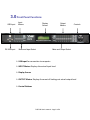
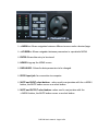
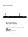
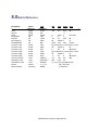
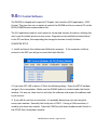
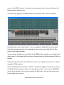
DSLP48 Loudspeaker Management System User Manual Firmware Version 9.02 SoAware Version 9.02 Table of Contents 1.0 Introduction ............................................................... 3 2.0 Features ..................................................................... 4 3.0 Front Panel Functions............................................... 5 4.0 Rear Panel Functions................................................ 7 5.0 Powering Up the Device............................................ 8 6.0 Operating the Device / Input menus......................... 9 6.3 Output Menus........................................................ 11 6.4 System Menus ...................................................... 13 7.0 Security/Password/ Locking ........................................ 16 8.0 Quick Reference......................................................... 18 9.0 PC Control................................................................... 19 10.0 Software Navigation.................................................... 22 10.1 Upgrading Software/Firmware …………………. 27 11.0 Specifications…………………………………………….. 28 12.0 Warranty…………………………………………………… 30 DSLP48 User's manual - Page 2 of 30 1.0 Introduction The DSLP48 is a complete 4 input -‐ 8 output digital loudspeaker management system designed for the touring or fixed sound installaJon markets. The absolute latest in available technology is uJlized with 40 bit floaJng point processors and high performance 24-‐bit Analog Converters. The high-‐bit DSP prevents noise and distorJon induced by truncaJon errors of the commonly used 24-‐bit fixed-‐point devices. A complete set of parameters include I/O levels, delay, polarity, 8 bands of parametric EQ per channel, plus 1/3rd oct graphic EQ on the Inputs, mulJple crossover selecJons and full funcJon compressors (Input) and limiters (Output). Precise frequency control is achieved with its 1 Hz resoluJon. Delay is adjustable in 10 us steps. MulJple setup storage and system security is integrated into the operaJng system. Inputs and outputs can be routed in mulJple configuraJons to meet any requirement. The DSLP48 can be controlled or configured in real Jme on the front panel or with the intuiJve PC GUI accessed via the RS-‐232/USB or Ethernet interface. SoAware and firmware upgrades for CPU and DSP via PC keep the device current with newly developed algorithms and funcJons as they become available. Shipped contents: -‐ DSLP48 unit -‐ User Manual -‐ DSLP Control SoAware CD DSLP48 User's manual - Page 3 of 30 2.0Features > 4 Inputs and 8 Outputs with flexible rouJng > 40-‐bit floaJng point DSP > High Performance 24-‐bit A/D Converters > 1 Hz Frequency ResoluJon > 8 Parametric Equalizers for each Input and Output >1/3rd octave graphic EQ for each input > MulJple Crossover types with Full FuncJon compressors on the inputs >MulJple Crossover types with hard limiJng on the outputs > Precise Level, Polarity and Delay on both inputs and outputs > CPU and DSP upgrade via PC > Individual Channel Buaons with Linking capability > 2-‐Line x 16 Character Backlit LCD Display > Full 5-‐segment LED on every Input and Output > Storage of up to 30 Program Setups > Security Lock > RS-‐232-‐USB-‐Ethernet Interface for PC Control, ConfiguraJon and Upgrading DSLP48 User's manual - Page 4 of 30 3.0 Front Panel Functions USB Input RS 232 Input Input Meters Display Screen Mute and Input Select Output Meters Controls Mute and Output Select USB input for connecJon to computer INPUT Meters Displays the actual Input level Display Screen OUTPUT Meters Displays the onset of limiJng-‐not actual output level Control Bu:ons DSLP48 User's manual - Page 5 of 30 <<MENU>> Allows navigaJon between different menus under a desired page <<CURSER>> Allows navigaJon between parameters in a parJcular MENU ENTER Allows data entry to be stored. HOME Brings up the HOME screen DATA WHEEL Allows for data parameters to be changed. RS232 Input jack for connecJon to computer MUTE and INPUT select bu:ons -‐ when used in conjuncJon with the <<MENU buaon, the MUTE buaon serves as a select buaon MUTE and OUTPUT select bu:ons -‐when used in conjuncJon with the <<MENU buaon, the MUTE buaon serves as a select buaon DSLP48 User's manual - Page 6 of 30 4.0Rear Panel Functions Switch, Fuse and Power connector Input/Output Ethernet connection Power switch -‐ Controls power On/Off. Main Fuse -‐ T200mA-‐250V. Slow blow type. Main Power -‐ Connects via a standard IEC socket. A compaJble power cord is supplied with the unit. The voltage input is either 115VAC or 230VAC and is clearly specified on the unit. Voltage requirement has to be stated upon ordering. Ethernet connecMon OUTPUT JACKS M XLR pin 2 Hot-‐ 3 Cold INPUT JACKS F XLR pin 2 Hot -‐3 Cold DSLP48 User's manual - Page 7 of 30 5.0 Powering Up the Device • AAer powering up the unit, the following iniJalizaJon screen is displayed on the LCD: • The iniJalizaJon process takes about 8 seconds and during that period the unit boots and displays the DSLP48 firmware version. • AAer the iniJalizaJon process is finished the DSLP48 displays its main screen: • The screen shows the current program number and program name currently loaded into the unit. The program assigned is always the last program the user recalled or stored before powering down the unit. • Now the DSLP48 is now ready to operate. DSLP48 User's manual - Page 8 of 30 6.0 Operating the Device 6.1 Channel Linking Channels can be linked by pressing the LEFT MENU KEYS and the MUTE buaon of the Input or Output keys, holding it down and pressing any other MUTE key in the same group (Input or Output group). The channels selected will be linked together. The green menu LEDs for the linked channels are lit. Any modificaJon of the data for the selected channel will be applied to the linked channels as well. To cancel the linking, press and hold the LEFT Menu key and a channel. 6.2 Input Menus Each of DSLP48 input channels has a separate Menu key. There are 6 menus for each input channel. The MENU buaons select the different blocks of the signal chain. The CURSOR buaons select the different parameters within that parJcular block. The DATA WHEEL selects the parJcular adjustment needed. Signal -‐ Signal parameters SIGNAL -‐ Gain, -‐40.00dB to +15.00dB in 0.25dB steps. POL -‐ Polarity, can be normal (+) or inverted (-‐). DELAY -‐ Delay in 10 us steps. Can be displayed in ms, A or m. The Jme unit of the delay can be changed in the System menu. The maximum delay permiaed is (90ms). EQ -‐ EQ parameters EQ# -‐ Selects one of the 8 available Equalizers. LEVEL -‐ EQ level gain. Ranges from -‐30.00dB to +15.00dB in 0.25dB steps. DSLP48 User's manual - Page 9 of 30 FREQ -‐ EQ center frequency. Ranges from 20 to 20,000Hz in either 1Hz steps or 1/36 octave steps. The sampling rate and the frequency steps can be selected in the System Menu. BW -‐ EQ Bandwidth. Ranges from 0.02 to 2.50 octaves in steps of 0.01 octave steps for PEQ. The Q value is automaJcally shown beneath the octave value. For Lo-‐Slf or Hi-‐Shf, it is either 6 or 12dB/Oct. I1: XXXXXX EQ BW: 0.33 Q=4.36 Type -‐ Type of EQ. The types can be parametric (PEQ), Lo-‐shelf (Lo-‐shf) and Hi-‐shelf (Hi-‐shf), AP (All Pass). There are 2 All Pass filters, AP 1 is a first order filter, AP2 is a second order filter. GEQ This is a standard 1/3rd octave graphic EQ on ISO centers (you cannot adjust the freq), but only the boost/cut. XOVER This allows for both high and low CUT filters of L/R, Bessel or Buaerworth types and 6-‐48dB/oct slope rates. COMP This is a compressor that allows for THRESHOLD, ATTACK, RELEASE (as a raJo of input Jme), RATIO, Ch-‐Name -‐ Channel Name • Name -‐ Channel name. It is 6 characters in length. • Use the cursor keys and the data wheel to enter the name DSLP48 User's manual - Page 10 of 30 6.3 Output Menus Each output channel of the DSLP48 has a separate menu key. There are 6 menus for each output channel. Signal -‐ Signal parameters Signal Level (Output gain)-‐Polarity-‐Delay funcJons are available just as on the input channels. EQ Refer to the Input Menus for details EQ -‐ EQ parameters XOver -‐ Crossover parameters Refer to the Input Menus for details • FRQL -‐ Filter cut-‐off Frequency of low frequency crossover point (low cut/ high pass). Ranges from 20 to 20,000Hz in either 1Hz steps or 1/36 octave steps. The frequency steps can be selected in the System General Menu. • SLPL -‐ Filter Slope of low frequency crossover point (low cut/high pass). Ranges from 6 to 48dB/octave. If the selected Filter Type is Linkwitz Riley, the available slopes are 12 / 24 / 36 / 48 dB/octave. FTRH -‐ Filter Type of high frequency crossover point (low pass). • FTRH -‐ Filter Type of high frequency crossover point (high cut/low pass). • FRQH -‐ Filter cut-‐off Frequency of high frequency crossover point (high cut/ low pass). • SLPH -‐ Filter Slope of high frequency crossover point (low pass). DSLP48 User's manual - Page 11 of 30 Filter ConfiguraMon None FTRL Highpass Lowpass Bandpass Low crossover point Off FTRL not Off FTRL Off FTRL not Off High crossover point FTRH Off FTRH Off FTRH not Off FTRH not Off FRQL FRQH FRQL FRQH Limit -‐ Output Limiter • THRESH -‐ Limit Threshold. Ranges from -‐20 to +20dBu in 0.5dB steps. The Threshold adjusts the output LEVEL meter to read the onset of limiJng-‐NOT output clipping. • ATTACK -‐ Aaack Jme. Ranges from 0.3 to 1ms in 0.1ms steps, then ranges from 1 to 100ms in 1ms steps. • RELEASE -‐ Release Jme. Can be set at 2X, 4X, 8X, 16X or 32X the aaack Jme. Source -‐ Input Source • 1,2,3,4 Input channel source for the current output channel. Can be set to enable the input source (On) or disable it (Off). If more than one input source are enabled, they will be added together as the source for the current output channel. The numbers indicate the gain of a parJcular input routed to that parJcular output. O1:XXXXXX Source In1:0.00 O1:XXXXXX Source In2:-10 O1:XXXXXX Source In3:Off O1:XXXXXX Source In4:2.5 Ch-‐Name -‐ Channel Name • Refer to the Input Menus for details DSLP48 User's manual - Page 12 of 30 6.4 System Menus The System Menus allow the user to control and change parameters that are related to the system behavior and general operaJon. It can be accessed by pressing the HOME and then ENTER key in the main menu. All System Menus require the Enter key to be pressed for the selected acJon. Recall -‐ Program Recall The DSLP48 has a built in non-‐volaJle memory that can store up to 30 different program setups. A program can be recalled using this menu. • PROG -‐ Program Number to be recalled. Only first 8 characters of the program name are displayed. Store -‐ Program store The DSLP48 has a built in non-‐volaJle memory that can store up to 30 different program setups. A program can be stored using this menu. The old program with the same program number will be replaced. Once the program is stored in the flash memory, it can be recalled at a later Jme, even aAer power down. • PROG -‐ Program Number for the current data to be stored. O1:XXXXXX Store PROG:01 • NAM -‐ Program Name, allows a maximum length of 12 characters. Use the cursor keys and data wheel for entry O1:XXXXXX Store NAM:XXXXXXXXXXXX Config -‐ Device ConfiguraMon • MODE -‐ configures the mode of operaJon. DSLP48 User's manual - Page 13 of 30 (System Menus con.nued) SYSTEM-SETUP MENU: ConQig MODE: 2-Way Mode: None Stereo 2-‐Way Stereo 3-‐Way Stereo 4-‐way In1 Out 1 Out 2 Out 3 Out 4 Out 5 Out 6 Out 7 Out 8 Any Any Any Any Any Any Any Any In1 In1 In2 In2 Any Any Any Any In1 In1 In1 In2 In2 In2 Any Any In1 In1 In1 In2 In2 In2 In2 The unit assigns the Input source for the corresponding outputs when the Mode of ConfiguraJon is selected. The crossover point parameters like the filter type, cut-‐off frequency and slope have to be configured manually in the Xover Menu in each Output menu. *Note: The configuraJon mode configures the input sources when selected. The user can change the source aAerwards if desired. It does not keep the configuraJon in memory. Individual crossover points will have to be adjusted as well. Copy -‐ Copy channels Copy Channels from the source to the target. When the Source and Targets are both Inputs or Outputs, all audio parameters will be copied. When one of the Source or the Target is an input while the other is an output, only the Level, Polarity, Delay and EQ are copied. • SOURCE -‐ Channel to be copied from. O1:XXXXXX Copy SOURCE: In1 • TARGET -‐ Channel to be copied to. O1:XXXXXX Copy TARGET: In2 DSLP48 User's manual - Page 14 of 30 (System Menus con.nued) General -‐ General system parameters SYSTEM-SETUP MENU: General FREQ MODE: All Freq DELAY UNIT: 01 DEVICE#: 1 • FREQ MODE -‐ Selects the frequency control mode for EQ and crossover filters. Can be 36 steps/octave or All Frequencies (1 Hz resoluJon). O1:XXXXXX Generl FREQ MODE: All • DELAY UNIT -‐ ms, A or m. O1:XXXXXX Generl DELAY UNIT: ms System ISO The System ISO ( Internal System OpJmizer) is a low level noise gate that turns on to let the signal pass. It is implemented to improve the signal to noise performance of the DSLP48. The default sepng is a threshold of 102. Most of the Jme this will be the best sepng. TO CHANGE THE ISO SETTING -‐hit the right menu buaon and enter to get into the System menu -‐ hit the right menu buaon 10 Jmes unJl the screen reads, “SYSTEM ISO” -‐ Use the parameter wheel to enter a new value, from 80 to 120. Hit enter to accept the value -‐ To BYPASS the ISO, go to the ISO screen per the direcJons above, then hit the curser right key. This will bring up “SYSTEM ISO Bypass:” turning the parameter wheel will turn bypass on or off. DSLP48 User's manual - Page 15 of 30 7.0 Security/Passwords/Locking The DSLP48 enables the user to secure the unit and prevent undesired changes in the setup. In order to lock/unlock the unit the user must enter the correct password. The DSLP48 is shipped from the factory with no password installed. When first connecJng to the DSP the user will see the following: If the computer and DSP are communicaJng correctly, clicking on Device 1 will bring up the following screen ***PLease Note: Once you have assigned a Password you will have to LOG IN to see the Security menu opJon. LOG IN is found under the Start menu*** To set password, Select SECURITY and follow prompts unJl you see the password window. The password of the DSLP48 is 4 characters in length. The user can change it as needed, but only from the host computer. See secJon 9 for connecJng the DSLP48 to a host computer. DSLP48 User's manual - Page 16 of 30 SelecJng LOCK CONTROLS from the Security Menu brings up the following window: This window allow the user to select the features that will be locked on the DSP. When the items are locked, the user will not be able to change the parameters from the DSLP48. The DSLP48 is shipped from the factory unlocked. If you purchased the unit used, the first thing you will need to do is to make sure your DSLP48 is unlocked. If the unit is locked you can see all funcJons but cannot make any changes via the front panel nor computer interface. You will need the password to unlock the unit. If you do not have the password, please contact Danley Sound Labs. To verify that the unit is unlocked: 1: Press the Upper LeA MENU key (on the control buaon on the right side of the unit) and while holding down-‐press one of the output Mute buaons, Release. This should bring up a screen with a Level control on it. Turn the data wheel and see if this level changes. If it does your DSP is unlocked. If it does not, follow the next steps. 2: If your unit is locked-‐proceed with the following. On the front of the DSP locate the control buaons towards the right side. Press the HOME buaon, then the ENTER buaon. If the unit is locked, The word SECURE will appear and space for the 4 digit password. Enter the Password using the data wheel and the cursor buaons. Now press ENTER-‐ TWICE. This should unlock your DSP. Try step 1 above to see if the unit is unlocked. DSLP48 User's manual - Page 17 of 30 8.0Quick Reference Parameters Menu Field Min Max Steps Units < <<Menu>> <<Cursor>> > Level Signal LEVEL -‐40 +15 0.25 dB Polarity Signal POL + / -‐ Delay Signal DELAY 0 2,400 1 21us step EQ Number EQ EQ# 1 8 1 EQ Level EQ LEVEL -‐30 +15 0.25 dB EQ Frequency EQ FREQ 20 20,000 1 Hz EQ Bandwidth EQ BW 0.0/2 3.61 0.01 Octave Crossover Low XOver FTRL Off / Bu5erworth / Linkwitz-‐Riley / Bessel Crossover Low XOver FRQL 20 20,000 1 Hz Crossover Low XOver SLPL 6 48 6 dB/octave Crossover High XOver FTRH Off / Bu5erworth / Linkwitz-‐Riley / Bessel Crossover High XOver FRQH 20 20,000 1 Hz Crossover High XOver SLPH 6 48 6 dB/octave Out Limit Thresh Limit THRESH -‐20 +20 0.5 dBu Out Aaack Time Limit ATTACK 0.3 100 0.1/1 ms Out Release Time Limit RELEASE 2 / 4 / 8 / 16 / 32X Aaack Jme Source Source 1, 2, 3,4 Off / On/Level Channel Name Ch-‐Name NAME 6 characters DSLP48 User's manual - Page 18 of 30 9.0 PC Control Software The DSLP48 is shipped with a special PC Graphic User Interface (GUI) applicaJon – DSLP Control. This gives the user an opJon to control the DSLP48 unit from a remote PC via the RS232/USB/Ethernet communicaJon link. The GUI applicaJon makes it much easier to control and monitor the device, allowing the user to get the whole picture on one screen. Programs can be recalled and stored from/ to the PC hard drive, thus expanding the storage to become virtually limitless. COMPUTER SETUP 1: Install and launch the soAware and follow the prompts. If the computer is able to connect to the DSP you will get a screen that looks like this: 2: If you have OFF LINE in device 1 Check the following things. Open the SETUP window and go to Port connecJons. Make sure the ONLINE buaon is checked under the Details window. If it was not, then check it and close the soAware and reopen the soAware and try to connect. 3: If you sJll do not have a connecJon, it is probably because you are not using the correct port number. Generally the Serial port is COM 1. If using a USB connecJon, it could be just about any number. Open the COM Port pull down window under Details in the SETUP-‐Port ConnecJons window. DSLP48 User's manual - Page 19 of 30 4: Scroll down and see if you have ports that have a blank beside the numbers. Most will say “not available”. If you have several with a blank, you will need to go to more detail to see which port is which. But if you only see one port that has a blank name then double-‐ click that number and it should be entered into the port number. You will need to close and restart the soAware for this change to take effect. 5: If you have several blanks then you will need to idenJfy which port is which. The soAware provides a shortcut to the Windows DEVICE MANAGER. It can be accessed by selecJng DEVICE MANAGER from the ConnecJon Setup window. Scroll down unJl you see Ports Com and LPT. Open that up. You should see the port number next to the parJcular device that is using it. If you are using USB to communicate with the unit, find the COM PORT which is assigned to the UART Bridge Controller as shown below. Note that number and then go back to step 4 above and enter that port number. DSLP48 User's manual - Page 20 of 30 6: In a few unusual cases you will need to make another change. Following the steps in #5 above, go to the com port being used and double click it. Then open the RESOURCES tab. In the middle there should be a box that says “Use automaJc sepngs”. It does not maaer whether the box is checked or not; change it, then hit CHANGE SETTINGS and close out the windows. It may take a couple of seconds for this change to take effect. NOTE: If you have to do step 6 with your computer, you will need to change it every Jme you start your computer up and use the DSP. You should now be able to connect to the device and go ONLINE. IMPORTANT! If you wish to perform a firmware upgrade, you must use the R232 connecMon. Some USB to Serial adaptors do not work correctly. If you try to perform an UPGRADE and it repeatedly fails, try another USB to Serial adaptor. DSLP48 User's manual - Page 21 of 30 10.0Software Navigation Click on a “CONNECTED” device and this basic DSP window will open. It is assumed that the user knows their way around the various func.ons available in modern DSP’s so the par.cular func.ons will not be discussed in detail, just basic opera.on/naviga.on. METERS The meters in the soAware indicate the actual level of the signal (unlike the panel display meters that show the onset of limiJng on the output). The DEVICE buaon in the top right side of the screen allows you to give the device a name-‐such as the name of the customer. If you have mulJple devices in a system, this is also where you would assign device numbers to each unit. DSLP48 User's manual - Page 22 of 30 The PRESETS tab in the boaom leA side of the screen allows you to transfer sepngs between the computer and the processor. SelecJng the “set current sepngs” will bring up the Windows “Open” window and allow the user to select a file (.xdat) to load and transfer to the processor. SelecJng the “save current sepngs” opJon will allow the user to save the current sepng in the processor to the computer. In the right hand window the user can assign sepngs to presets in the processor. INPUT CHANNELS If you click on the 1st tab on the leA (for example IN 1). This will open up all the funcJons available for that parJcular input. If you want to name the input click on the NAME window unJl it turns white with a flashing curser. Type in the name you want and hit ENTER. It will turn Red-‐unJl you go somewhere else on the screen and then the screen will retain the name you gave it. Along the boaom of the window there are 4 groups of up/down buaons. The small ones on the leA, will increment the value in a selected box in the smallest increment allowed. The larger arrows increment the value in larger increments. As a general rule only the data in the DARK BLACK screens can be changed. The data in the lighter black windows is there for reference. For example, at the top leA of the DSLP48 User's manual - Page 23 of 30 screen, in the DELAY secJon, the data must be entered in ms, but you will also see the Meter and foot distances also. The same thing applies for the EQ secJon and bandwidth and Q. Enter the data in Bandwidth and see the Q equivalent. You can change the bandwidth by entering the parJcular number you want or by dragging the open circles associated with the filter center in the display window. You can change the filter type by clicking on the PEQ window and then use the black up/ down arrows at the boaom of the screen to change to various different types of filters as needed. NoJce that that each of the four INPUT channels has an eight band parametric as well as a graphic ( GEQ) equalizer. There are high and low pass filters available. In order to engage or change them, click on the NONE window under the high or low pass filter you want. Then use the UP/DOWN arrows at the boaom of the screen to change the filter type. You can also do the same for the slope rate you want. DSLP48 User's manual - Page 24 of 30 OUTPUT Channels The output controls work preay much the same as the input channels-‐so be sure to read that first. There are a few excepJons. There is a MIXER on the output side of each DSP channel. It is accessed by clicking on the box directly above the “POLARITY” box. There will be a number in it. This number indicates which input channels are routed to it. For example if you have a 1 in the box, then input 1 is routed to that parJcular output. If you have a 124, that means that input channels 1 and 2 and 4 are routed to that parJcular output. But these numbers give no indicaJon to the parJcular level of those inputs, they simply indicate that there is some level above full aaenuaJon. If you click on the mixer box you will see a mixer field open up with level controls. These are the parJcular level of the inputs going to that output. The EQ secJon of the output channels has eight band parametric but no GEQ. The output channels also have limiters rather then the compressors available in the input secJon. DSLP48 User's manual - Page 25 of 30 The output meters (both on the DSP front panel and in the soAware) may not operate in the way you would normally think. They are referenced to the LIMITER trigger point. So if the limiter threshold is all the way up, then they are for the max output of the device. But as the limiter threshold is turned down, the red “peak” meter is the onset of limiJng. The output limiter differs from the input compressor in that you cannot adjust the raJo. This is designed solely to keep amplifiers out of clip, while the input compressor can be used for any number of various things as needed-‐smoothing out a signal-‐long term level reducJon etc. Just adjust the parameters as needed. NOTE: It is important that you save the current se7ngs to the DSP before turning it off-‐ or they will be lost. When the DSP is powered up it will revert to the last saved se7ngs. DSLP48 User's manual - Page 26 of 30 10.1 Upgrading Software/Firmware From Jme to Jme Danley Sound labs will release new soAware and or firmware that will enhance or improve the funcJonality of the DSLP48. There will be a noJce posted on our website announcing the soAware/firmware upgrades and links for downloading the new files. ***IMPORTANT*** Back up all Qiles from the DSP to your host computer as performing a Qirmware upgrade will erase EVERYTHING in the DSP, including passwords! For Upgrading both software and Qirmware. 1. 2. 3. 4. 5. 6. 7. 8. 9. 10. 11. 12. 13. Download the software 1iles from the Danley website or import them from a Danley supplied CD. Install the software and follow the prompts. Have a USB to Serial adaptor available and make sure that the appropriate driver is installed. Connect the computer to the DSLP48 using a Serial cable or a USB to serial adaptor. Launch the Software and insure that the Computer is communicating with the DSLP48. If the DSLP48 is password protected, log on and enter the password. Select the menu item “ UPGRADE” and “FIRMWARE” . Remember to back up all 1iles before proceeding. You will be prompted to locate the .img 1ile that is the 1irmware upgrade. Select the appropriate .img 1ile and click open. The 1irmware upgrade should begin. with a progress bar showing at the bottom of the screen. Make sure that the DSLP is not turned off or the connection interrupted until the upgrade is complete. NOTE! There are some USB to Serial adaptors which will permit control of the DSLP48, but will not allow the UPGRADE to properly transfer. If the UPGRADE fails repeatedly, try a different adaptor. Power cycle the DSLP48. ( power down and up again) It should come up showing the latest 1irmware version in the display screen. Restart the software, reload the password and setting. as needed. DSLP48 User's manual - Page 27 of 30 11.0 Specifications Inputs and Outputs Input Impedance: Output Impedance: Maximum Level: Type: >10k Ohms 50 Ohms +20dBu Electronically balanced Audio Performance Frequency Response: Dynamic Range: CMMR: Crosstalk: DistorJon: +/-‐ 0.1dB (20 to 20kHz) 115dB typ (unweighted) > 100dB (50 to 10kHz) < -‐100dB 0.002% (1kHz @+4dBu) Digital Audio Performance Processor: 40 bit floaJng point Sampling Rate: 48kHz Analog Converters: High Performance 24-‐bit PropagaJon Delay: 1.5ms Front Panel Controls Display: Level Meters: Buaons: Dial Encoder: 2 x 16 Character Backlit LCD 5 segment LED 12 Mute Controls Embedded Thumb Wheel Connectors Audio: 3-‐pin XLR RS-‐232: Female DB-‐9 USB Type B Ethernet Standard Caa 5 RJ45 Power: Standard IEC Socket DSLP48 User's manual - Page 28 of 30 General Power: Dimensions: Weight: 15 / 230 VAC (50 / 60Hz) 19” x1.75” x9” (483x44x203 mm) 10 lbs. / 4.6kg Audio Control Parameters Gain: -‐40 to +15dB in 0.25dB steps Polarity: +/-‐ Delay: Up to 90ms per input and output in 10 us steps (180ms total per path) Equalizers (8 per I/O) Type: Gain: Bandwidth: Parametric, Hi-‐shelf, Lo-‐shelf and GEQ (on inputs) -‐30 to +15dB in 0.25dB steps 0.02 to 3.61 octaves (Q=0.311 to 72) Crossover Filters (2 per Output) Filter Types: Buaerworth, Bessel, Linkwitz Riley, FIR Slopes: 6 to 48dB/oct Limiters Threshold: -‐20 to +20dBu Aaack: 0.3 to 100ms Release: 2 to 32X the aaack Jme RaJo: 1:1-‐1:40 (compressor only) System Parameters No. of Programs: Program Names: Delay Units: Frequency Modes: Security Lock: Copy channels: Channel Names: 30 12 character length ms, A, m 36 steps/oct, 1Hz resoluJon Lock/Unlock All parameters 12 character length Note: SpecificaJons subject to change without noJce DSLP48 User's manual - Page 29 of 30 12.0 Warrantee The DSLP48 is warranted covering materials and workmanship for a period of one (1) year, as determined by the date of retail purchase (according to the sales receipt from an authorized dealer) or the date of manufacture if the sales receipt is not available (according to the serial number). This warranty applies to the product; therefore, the remainder of the warranty period will be automaJcally transferred to any subsequent owner. This warranty applies only to failure of a Danley Sound Labs product caused by defects in materials and workmanship during the stated warranty period. It does not apply to a unit that has been subjected to abuse, accident, modificaJon, improper handling/installaJon, or repairs made without factory authorizaJon or by anyone other than authorized Danley Field Service StaJons. This warranty is void if the serial number has been defaced, altered or removed. Products covered by this warranty will be repaired or replaced at the opJon of Danley, without charge for materials or labor, provided all the terms of this warranty have been met. For factory service, please call or email for a Return AuthorizaJon (R/A) number before shipping. If the product is shipped, the following informaJon must be included in the package: 1. Owners complete name, dayJme phone number, return street address and return authorizaJon number. 2. The serial number of the product being returned and a copy of the retail sales receipt, if possible. 3. A complete descripJon of the problem(s) experienced, including a brief descripJon of how the equipment is being used and other equipments involved. User Manual v3.0 (FEB 2009) Danley Sound Labs Phone: (770) 535-‐0204 2196 Hilton Drive, Suite G, Gainesville, Georgia 30501 Fax: (770) 535-‐8485 www.danleysoundlabs.com DSLP48 User's manual - Page 30 of 30