1
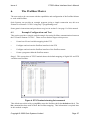
PTS/Profibus Interface Software User’s Manual Issue 4 November 2002 MAN537 Copyright Notice Copyright 2002 Quin Systems Limited. All rights reserved. Reproduction of this document, in part or whole, by any means, without the prior written consent of Quin Systems Limited is strictly prohibited. SERVOnet is a registered trade mark of Quin Systems Ltd. Software Version This manual reflects the following firmware/software versions: • PTS Firmware version 2.2.1.1 or later • PTS/Profibus interface version 1.4 Important Notice Quin Systems reserves the right to make changes without notice in the products described in this document in order to improve design or performance and for further product development. Examples given are for illustration only, and no responsibility is assumed for their suitability in particular applications. Although every attempt has been made to ensure the accuracy of the information in this document, Quin Systems assumes no liability for inadvertent errors. Suggestions for improvements in either the products or the documentation are welcome and should be addressed to:Quin Systems Limited Oaklands Business Centre Oaklands Park Wokingham Bershire RG41 2FD Telephone: Facsimilie: E-Mail: WWW Site: 0118 977 1077 0118 977 6728 [email protected] http://www.quin.co.uk/ Issue 4 PTS/Profibus Interface User’s Manual Contents 1. Introduction 1.1 Getting started information 1.2 General 1.3 Profibus Concepts 1.4 Host I/O and Variable Mapping 2. Getting started guide 2.1 Check #1: Equipment and Connections 2.1.1 PTS 2.1.2 Profibus Master 2.1.3 Equipment Layout Schematic 2.2 Check #2: Design decisions 2.2.1 Design decision #1: Profibus bus address 2.2.2 Design decision #2: Profibus Receive data area 2.2.3 Design decision #3: Profibus Send data area 2.3 Check #3: Configuring PTS (Profibus Slave) 2.4 Check #4: Configuring Profibus Master 2.5 Potential Problems 7 7 7 7 8 9 9 9 10 11 11 11 3. Configuring the PTS for Profibus 3.1 Hardware 3.2 Software License Key 3.3 Configuration Shell 3.3.1 Accessing the Shell 3.3.2 Apply Configuration 3.3.3 Busaddr Command 3.3.4 Clear Mapping 3.3.5 Consistency Command 3.3.6 Default Variables 3.3.7 Force Variable Mapping 3.3.8 Info Command 3.3.9 IO Command 3.3.10 List Command 3.3.11 Map a Variable 3.3.12 Poll interval 3.3.13 Quit/Exit from Shell 3.3.14 Restore Configuration 3.3.15 Save Configuration 3.3.16 Unmap a Variable 3.3.17 Upload Configuration 3.4 Error messages 12 12 12 13 13 14 14 14 14 15 15 15 16 17 18 19 19 19 19 19 19 20 4. Programming the PTS 4.1 Host I/O 4.2 Variables 4.3 Arrays 22 22 23 23 5. The COM-DPS Daughter Board 26 Copyright © 2002 Quin Systems Limited 4 4 4 5 5 Page 2 Issue 4 PTS/Profibus Interface User’s Manual 6. The Profibus Master 6.1 Example Configuration and Test 27 27 7. Hardware Configuration 7.1 Profibus Connections 7.2 Serial Connections 7.3 LEDs 7.4 CPU360 Board Layout 31 31 31 32 33 Copyright © 2002 Quin Systems Limited Page 3 Issue 4 PTS/Profibus Interface User’s Manual 1. Introduction 1.1 Getting started information A new section, Getting started guide on page 7, includes updated and clarified information on the configuration of the PTS/Profibus interface. 1.2 General This manual relates to the following versions of software in the PTS unit: Profibus Interface PTS Host software Version 1.4 Version 2.2.1.1 or later This document describes the PTS/Profibus interface implemented using the COM-DPS interface of the CPU360 (PTS Mk2 or SERVOnet Machine Manager). The PTS acts as a Profibus-DP slave which is intended to be controlled by a master PLC or PC device on the Profibus network. The Profibus-DP network is designed for high speed data communication between central controllers (PLCs, PCs, etc.) and distributed field devices (I/O, drives, etc.). At the physical level the network consists of a twisted pair, two wire cable using RS-485 signals at baud rates from 9.6 kB up to 12MB. Data communication between the central controller (the master) and the field devices (the slaves) happens cyclically. On each cycle the master device reads the input data from the slaves and writes the output data to the slaves. The amount of data read or written is limited to 512 bytes and is fixed during network configuration. The master PLC/PC can access a user defined set of PTS variables for reading and writing. Up to 240 variables or array elements can be mapped onto Profibus. The variables can be used to control the PTS either as trigger variables to start actions or as parameters such as running speed, length, etc. The variables can also be used to pass operating information back to the PLC/PC such as positions, I/O status, etc. As well as variables the master PLC/PC can access the host I/O on the PTS. The host I/O consists of 64 virtual inputs and 64 virtual outputs which can be used for many of the same functions as the physical digital I/O. The PTS host I/O bits map onto the Profibus discrete I/O bits such that when the master node writes to an output bit the result appears in the corresponding PTS host input bit. Similarly when the master node reads an input bit it gets the contents of the corresponding PTS host output bit. Host inputs are supported by the DI, II and RI commands while host outputs are supported by the SO, CO, IO and RO commands. Copyright © 2002 Quin Systems Limited Page 4 Issue 4 1.3 PTS/Profibus Interface User’s Manual Profibus Concepts Unlike traditional asynchronous command-response protocols, Profibus-DP operates on data. Instead of providing a medium where network nodes can perform numerous instantaneous packet based conversations, Profibus-DP provides a medium where the network nodes all appear to share a block of memory which they can read from or write to at any time. In fact there are two such blocks involved known as Process Data Images because they provide an image of the process data on some network node. The two blocks are the Receive Process Data Image and the Send Process Data Image. The Receive Process Data Image receives its data from Profibus and is the image of the process data on the remote node. The Send Process Data Image sends its data to Profibus and is the image of the process data on the local node. The relationship between the send and receive process data images on the PLC and the PTS is shown in the following diagram. PLC PTS Send Process Data Image Receive Process Data Image Profibus-DP Receive Process Data Image Send Process Data Image Figure 1. Process Data Images 1.4 Host I/O and Variable Mapping In the PTS each process data image is a block of data up to 136 bytes long: The first 8 bytes (addresses 0 to 7) can be mapped onto the 8 host I/O groups. For the receive process data image the first byte at address 0 goes to host input group 10, the second byte at address 1 goes to host input group 11 and so on. For the send process data image the first byte at address 0 comes from host output group 10, the second byte at address 1 comes from host output group 11 and so on. On the Profibus master the host I/O forms two modules, one 8 byte input (for PTS host outputs) and one 8 byte output (for PTS host inputs) which should be mapped to an appropriate address in the Profibus master and addressed as individual bits, corresponding to individual I/O lines. (It is an option to turn off host I/O if not required). The next 128 bytes (either address 8 onwards if host I/O used, or starting at address 0) of each process data image is mapped to a set of variables or array elements defined by the user. To make best use of the space available each variable can be mapped to a single byte, two bytes (a word) or four bytes (a long word or long). Mapping variables to a byte or a word increases the number of variables which can be mapped onto the process data image but restricts the range of the data which can be transferred. A byte can only hold values between 0 and 255. A word Copyright © 2002 Quin Systems Limited Page 5 Issue 4 PTS/Profibus Interface User’s Manual can only hold values between 0 and 65535. In contrast a long can hold values between ±2147483647. On the Profibus master this mapping appears as one or modules, of varying length (n word input or n word output as appropriate) as decided by the mapping defined by the user. The Profibus interface on the PTS works by scanning the receive and send process data images every 4ms approx. (for host I/O) and multiples of this (default 2 = 8ms) for PTS variables/ arrays. When the send image is scanned the first 8 bytes are taken from host output groups 10 to 17 (if host I/O is selected). If any variables/array elements are mapped to the send image the data is read from the appropriate variables/array elements and placed in the send image. When the receive image is scanned the first 8 bytes are sent to host input groups 10 to 17 (if in use). If any variables/array elements are mapped to the receive image the data is read from the receive image and if it has changed value since the last scan (value on Profibus NOT EQUAL to value in PTS) the value is written to the appropriate variable(s)/array element(s). The reason for writing to the variables only when the data changes is to stop trigger variables being activated on each scan which would cause unnecessary load on the processor. The following diagram shows an example of the receive process data image. The image has two variables mapped as bytes at addresses 8 and 9, two variables mapped as words at addresses 10 and 12 and one array element mapped as a long at address 14. PTS Receive PDI Profibus-DP 0 Group 10 1 Group 11 2 Group 12 3 Group 13 4 Group 14 5 Group 15 6 7 Group 16 8 $IN1 9 $IN2 10 11 12 13 Host Inputs Group 17 $IN3 Variables $IN4 14 15 16 $IN[5] 17 Figure 2. Receive Process Data Image Mapping Example (PTS) Copyright © 2002 Quin Systems Limited Page 6 Issue 4 2. PTS/Profibus Interface User’s Manual Getting started guide This section forms a guide to configuring the PTS/Profibus interface and should be used as a check list; follow the references to other sections of this manual. 2.1 Check #1: Equipment and Connections There are two distinct parts to the configuration of the PTS/Profibus interface: 2.1.1 PTS The PTS system should be equipped with Profibus daughter board and software key; see section 3. on page 12 of this manual. Configuring the PTS is done via PTS Terminal, part of PTS Toolkit 2000. You need to be familiar with PTS Terminal and have a serial or ethernet connection to the PTS system. 2.1.2 Profibus Master You need to be familiar with the use and configuration of your chosen Profibus Master. This will require a GSD file to tell it the capabilities of the PTS/Profibus interface: HIL_7501.GSD Latest: V3 31st October 2000 This can be found on the PTS Toolkit 2000 CD or Quin support web site: http://www.quin.co.uk/support Note: V3 of this file requires firmware 1.030 or newer in the Profibus daughter board. To find out the version of the firmware in the daughter board use the info command in the Profibus shell, PB (see section 3.3 on page 13 of this manual). Please refer to Quin Systems for upgrade issues if required. Copyright © 2002 Quin Systems Limited Page 7 Issue 4 2.1.3 PTS/Profibus Interface User’s Manual Equipment Layout Schematic The PTS/Profibus interface requires the following connections (here looking at the front panel of the SERVOnet Machine Manager/PTS Mk2. Top #2 Profibus connection COMPRO serial connection (advanced use only) Profibus indicators #1 PTS Terminal, PC serial connection to Port A Port B AUI 10-base T Ethernet (alternative PTS Terminal connection) CANopen (CAN1) SERVOnet (CAN0) Bottom Figure 3. Connections required for PTS/Profibus Interface Note: Information on the Profibus indicators can be found in section 7.3 on page 32 of this manual. Copyright © 2002 Quin Systems Limited Page 8 Issue 4 PTS/Profibus Interface User’s Manual Check #2: Design decisions 2.2 Before any (re)configuration of the PTS/Profibus interface can start three key design decisions need to be made. Design decision #1: Profibus bus address 2.2.1 The PTS will require a Profibus address. This is set using the busaddr command in the Profibus shell, PB. Design decision #2: Profibus Receive data area 2.2.2 The PTS can provide an amount of "receive" data for the Profibus Master. Be careful of this: PTS (PB) shell "Send" (output) = PLC "Receive" (input) The first 8 bytes of the PTS/Profibus interface are used for virtual outputs on the PTS system. This provides 64 binary signals from the PTS to the Profibus master. • This host I/O mapping may be removed if not required (io command, section 3.3.9 on page 16). A further 128 bytes can be configured in many different combinations using PTS variables or array elements. This gives a number of design decisions: • How many separate integer values are required. This is decided by the information that is required from the PTS, e.g. status codes and faults codes. • For each separate integer value how much data is required (choose from 1 byte, 2 byte or 4 byte, as explained in section section 1.4 on page 5 of this manual). But note: • There may be problems with the chosen mapping if it creates too many modules on the Profibus; the apply command will warn if this is the case; and an alternative mapping needs to be chosen. • The Profibus Master may have byte/word alignment issues; so this may restrict the choices that can be made. • The Profibus Master may have a limit on the amount of data it can receive from the PTS/Profibus interface - this may restrict the data area to less than the PTS can provide. • It is possible to define a "sparse" mapping on the PTS, i.e. you can set the size and location of a PTS variable in the Profibus data area. This allows for alignment issues. This decision will need implementing in the PTS, and in the Profibus Master. Use the apply, list and info command in the Profibus shell, PB, on the PTS to provide information about the outcome of this decision. Copyright © 2002 Quin Systems Limited Page 9 Issue 4 PTS/Profibus Interface User’s Manual Design decision #3: Profibus Send data area 2.2.3 The Profibus Master can send data to the PTS. Be careful of this: PTS (PB) shell "Receive" (input) = PLC "Send" (output) The first 8 bytes of the PTS/Profibus interface are used for virtual inputs on the PTS system. This provides 64 binary signals from the Profibus master to the PTS. • This host I/O mapping may be removed if not required (io command, section 3.3.9 on page 16). A further 128 bytes can be configured in many different combinations using PTS variables or arrays. This gives a number of design decisions: • How many separate integer values are required. This is decided by the information that is required by the PTS, e.g. instructions or configuration values. • For each separate integer value how much data is required (choose from 1 byte, 2 byte or 4 byte, as explained in section section 1.4 on page 5 of this manual). But note: • There may be problems with the chosen mapping if it creates too many modules on the Profibus; the apply command will warn if this is the case; and an alternative mapping needs to be chosen. • The Profibus Master may have a limit on the amount of data it can send to the PTS/ Profibus interface - this may restrict the data area to less than the PTS can provide. • The send data area does not need to be an exact duplicate of the receive data area; different PTS variables and different data sizes can be used. • It is possible to define a "sparse" mapping on the PTS, i.e. you can set the size and location of a PTS variable in the Profibus data area. This allows for alignment issues. This decision will need implementing in the PTS, and in the Profibus Master. Use the apply, list and info command in the Profibus shell, PB, on the PTS to provide information about the outcome of this decision. Copyright © 2002 Quin Systems Limited Page 10 Issue 4 2.3 PTS/Profibus Interface User’s Manual Check #3: Configuring PTS (Profibus Slave) Using PTS Terminal enter the PB configuration shell on the PTS system. Using the commands documented in section 3.3 on page 13 of this manual create the PTS variable mapping you have decided upon; following these generic steps: • clear to remove any previous configuration. • busaddr to set the Profibus address. • io to enable/disable the host I/O. • map to map a PTS variable to send/receive data areas (repeat this step until finished). • apply which checks the map for validity and creates module data areas. • list and info to display the results of this work. • save to store this configuration in NVM. • upload to make a record of the configuration (and save the text to PC disk). • quit to end this configuration. 2.4 Check #4: Configuring Profibus Master The Profibus Master will require the HIL_7501.GSD file to tell it the capabilities of the PTS/ Profibus interface. How this is done is dependent upon the configuration software used; however the following generic steps will apply: • Install (import) the HIL_7501.GSD file into the Profibus Master configuration software. • Insert (add) the PTS to the Profibus network. Look for ’Sonstiege’ and/or ’COM-DPS’. (you will not find any reference to PTS or Quin). • Configure the COM-DPS Profibus Slave; bus address, network speed and I/O configuration (send/receive data area size and type - use the information in the info command from the PTS Profibus shell, PB) See section 6.1 on page 27 for an example of this. 2.5 Potential Problems There is no automated cross-checking between the PTS configuration, and the Profibus Master configuration. The Profibus network will not communicate properly unless both the Profibus master and the PTS (Profibus slave) are using matching configurations. Use the info command in the PTS Profibus shell, PB, to obtain important information about the configuration, state and operation of the Profibus. Furthermore there is no checking for the PTS variable/array element mapping on the Profibus master; so it is possible to address only parts of variables, or overlap addresses; use the list command in the PTS Profibus shell, PB, to obtain an address list of the host I/O and PTS variables/array elements. Copyright © 2002 Quin Systems Limited Page 11 Issue 4 PTS/Profibus Interface User’s Manual 3. Configuring the PTS for Profibus 3.1 Hardware Before switching the PTS on check that the COM-DPS interface board is in place on the CPU360 processor board. Without this interface board the Profibus software will not work. Also check that the CPU360 is an Issue E board or later. Refer to section 7.4 on page 33 for a diagram of the CPU360 and COM-DPS interface board. 3.2 Software License Key The software for the Profibus interface will not operate unless a software key has been entered to enable this option. The software key is different for each PTS and can be obtained from your sales office given the system serial number which can be found by using the SK command as shown below. To enable the software the following command should be entered on Port A (the main programming port) in privileged mode. You enter the text in bold while the PTS displays something similar to the rest. 1> SK Serial number: 006545 Feature Version Key New feature ? profibus Version ? 1.4 Key ? abcd OK Note that the feature name (profibus) must be entered in lower case exactly as shown above. Note also that it is necessary to turn the power off and back on again to run the Profibus software. The key value is dependent on the unit serial number and should be obtained from your Quin sales office. If the software needs to be disabled, first make a note of the software key in case it is needed in the future. Then proceed as above but simply press the Return key in response to the “Version ?” prompt as follows. 1> SK Serial number: 006545 Feature Version Key profibus 1.4 ABCD New feature ? profibus Version ? Feature profibus removed Copyright © 2002 Quin Systems Limited Page 12 Issue 4 PTS/Profibus Interface User’s Manual 3.3 Configuration Shell 3.3.1 Accessing the Shell The Profibus configuration shell is a command interface specific to Profibus which allows you to configure the variables for Profibus, save the configuration, etc. Use PTS Terminal, part of PTS Toolkit 2000. Connect to the PTS via serial or ethernet; and ensure the PTS is in privileged mode (PM). To enter the shell type the PB command: 1> PB pb> The pb> prompt shows that the configuration shell is ready for a new command. Typing help makes the shell display a list of available commands as follows: pb> help apply Apply setting now busaddr Profibus address clear Unmap all variables consistency <module> <yes (1)/no (0)> Set whether modules on Profibus use consistency default Reset variable mapping to the default force <var> [<addr>] recv|send [byte|word|long] Same as map but does not check for overlap information Display configuration information io Enable/disable host I/O mapping help Display list of commands list Display current I/O and variable mapping map <var> [<addr>] recv|send [byte|word|long] Map variable at optional specified address poll Set poll interval for PTS variables quit Quit from this shell restore Restore variable mapping from NVM save Save variable mapping to NVM unmap <var> recv|send Unmap variable from receive, send or both maps upload Output mapping as commands to logfile If Profibus is not enabled an error message is displayed instead: 1> PB Profibus is not enabled 1> In this case you need to enter a software license key as described in section 3.2 on page 12 and cycle the power to the PTS to start the Profibus software. The remainder of this chapter lists these commands alphabetically; two important notes: 1. use the APPLY command followed by the INFO command to check results. 2. use the SAVE command to store your configuration. Copyright © 2002 Quin Systems Limited Page 13 Issue 4 3.3.2 PTS/Profibus Interface User’s Manual Apply Configuration The apply command configures the Profibus interface for use; it applies all the settings of busaddr, io, poll and map. This command should be issued after changes have been made and before any attempt is made to use the Profibus interface. The apply command also creates all the modules for the Profibus send and receive images; these are the size and type of mapping required in the Profibus master. The info command lists out the modules, their size and type. The following module types are used: For host I/O (if enabled): one 8 byte input and one 8 byte output module with or without consistence (as set by consistency). For PTS variables/array entries: A number of word input or output (as appropriate) modules, with or without consistence, and of 16, 12, 8, 4, 3, 2 or 1 word length. The number of modules and their lengths are calculated to avoid splitting PTS variables across module boundaries and to minimise wastage (unused bytes). It is possible for this module creation to report error message(s) due to the number and size/ position of the PTS variables and/or arrays used in the send and/or receive maps. If an error message is reported try re-arranging the variable maps to avoid the error. See section 3.4 on page 20 for a full listing of error messages and how to avoid them. 3.3.3 Busaddr Command The busaddr command sets/reads the Profibus address for the PTS. This can be set to any number between 1 and 126 inclusive. To read the current value use the info command or type busaddr without any parameter. 3.3.4 Clear Mapping The clear command clears the variable mapping. It is equivalent to unmapping all mapped variables. It is normally used to clear the variable map to known empty state before downloading a variable configuration file. 3.3.5 Consistency Command Profibus data can be transmitted with or without consistency (network data checks). This is an advanced configuration and should be used with care - the same settings need applying to the Profibus master when mapping the PTS into the Profibus address space. The info command will list all the modules created by the data mapping from the PTS to/from Profibus. There will be up to 12 modules (numbered 0 to 11). If host I/O is enabled the first two modules will be 8 bytes mapping onto the host I/O. The consistency command lets you set for each of the 12 possible modules whether data consistency is used. Typing the consistency command without any parameters lists the current settings. Syntax: consistency <module 0 to 11> <0 = off, 1 = on>. The info command will show when consistency has been used. Copyright © 2002 Quin Systems Limited Page 14 Issue 4 3.3.6 PTS/Profibus Interface User’s Manual Default Variables The default command maps the default set of variables onto Profibus. This results in variables $R1 to $R12 being mapped as long (4 bytes) on the receive process data image; and $P1 to $P12 being mapped as long (4 bytes) on the send process data image. The default command does NOT change the setting of busaddr, consistency, io or poll. 3.3.7 Force Variable Mapping The force command does the same as the map command but does not ask for confirmation if you are about to overwrite an existing variable. It is not intended to be used directly for configuring the variable map as it is less safe than the map command. It is provided mainly for use by the upload command described section 3.3.17 on page 19. 3.3.8 Info Command The info command produces a textual output of the current status and configuration of the PTS Profibus interface: Information Report ================== Hardware -------Date: Serial: Firmware name: Firmware version: Driver type: Status: Configuration ------------Bus address: Module 0: Module 1: Module 2: Module 3: Module 4: Module 5: Module 6: Module 7: Parameters ---------Baud Rate: Bus address: Ident number: Task state: Receive image size: Send image size: Error count: Last Error: 1 4 1999 00492 DPS COM-DPS V01.050 04.07.02 42 (should be 42) Ready Communicating 9 8 byte input 8 byte output 16 word input 16 word output 16 word input 16 word output 16 word input 16 word output 12000 kBaud (truncated value) 15 (actual) 7501 (should be 7501 for COM-DPS) 0010 72 (bytes) 72 (bytes) 0 0 This text provides some very necessary information required to configure the Profibus master, and also to help diagnose faults. The following lines should be checked: Copyright © 2002 Quin Systems Limited Page 15 Issue 4 PTS/Profibus Interface User’s Manual • Firmware name and version; should be as listed here; though firmware could be newer. • Driver type. This should be 42; if a different value is reported please check the board is mounted correctly, try the apply command, and if this fails please contact Quin Systems Ltd. • Status. This can have a number of messages; ready - the Profibus daughter board is working initialising - the Profibus daughter board is not ready communicating - the Profibus interface is configured offline - the Profibus interface is not configured correctly and so cannot communicate exchanging data - the Profibus master is successfully communicating with the PTS comms error - there is a communications problem on the network In the example given above the Profibus master is not communicating with the PTS, but the Profibus interface is ready and able (configured). • Configuration. This information is required to set up the Profibus master correctly - it is displayed in terms as used in the Profibus master (output/input refer to Profibus master not PTS). Modules - these are how the Profibus send and receive images are divided up on the network. On the Profibus master these require selecting to make the mapping - so use this list to correctly configure the Profibus master (enter modules/slot in the order displayed, and of size/type displayed). Refer to section 6.1 on page 27 for one example of how this module mapping should be applied. The modules listed here are name the same as the list in the information the Profibus master configuration software extracts from the HIL_7501.GSD file. (so input means input to the Profibus master, i.e. the send image from the PTS) • Parameters. These show what is actually happening; note the discrepancy between the Profibus address and image size wrt. configuration; this snapshot was not running properly (changes had been made but the apply command had not been issued). Profibus baud rate is shown as an integer, so 93.75 kbaud displays as 93. Task state has four digits, read as follows: xxx1: Initialising; this should clear after a few seconds xx1x: Running (initialisation has passed successfully) x1xx: Static diagnosis: Profibus is in a diagnostic mode 1xxx: Data exchange: the Profibus master and the PTS are actively exchanging data. 3.3.9 IO Command The IO command enables or disables the host I/O mapping onto Profibus. Default is IO 1 i.e. mapped to Profibus. Changing this option to IO 0 will remove the host I/O mapping from Profibus. This saves 8 bytes in the send and 8 bytes in the receive data areas. Typing IO without a parameter will display the current setting. Note: the host I/O commands work in PTS whatever the setting of this Profibus configuration parameter. Copyright © 2002 Quin Systems Limited Page 16 Issue 4 PTS/Profibus Interface User’s Manual 3.3.10 List Command The list command shows how host I/O and variables are mapped onto the receive and send process data images as shown in the following example: pb> list Address 0 1 2 3 4 5 6 7 8 12 16 20 24 Receive I/P Grp I/P Grp I/P Grp I/P Grp I/P Grp I/P Grp I/P Grp I/P Grp R1 (4) R2 (4) R3 (4) R4 (4) R5 (4) 10 11 12 13 14 15 16 17 Address 0 1 2 3 4 5 6 7 8 12 16 20 24 Send O/P Grp O/P Grp O/P Grp O/P Grp O/P Grp O/P Grp O/P Grp O/P Grp P1 (4) P2 (4) P3 (4) P4 (4) P5 (4) 10 11 12 13 14 15 16 17 The left hand pair of columns show the mapping in the receive process data image (data received by the PTS from the Profibus master). The right hand pair of columns show the mapping in the send process data image (data sent by the PTS to the Profibus master). The address column shows the byte address within the process data image for the object in the next column. The first 8 addresses are used for host I/O groups 10 to 17 (when enabled). Addresses above the host I/O mapping are used for variables. In this case the receive and send columns show the variable name followed by the number of bytes mapped in brackets. pb> list Address 0 Receive V1 (4) 4 V2 (4) 12 13 V4 (1) B1 (4) Address 0 1 Send X2 (1) A[1] (4) 10 12 X3 (2) POS (4) 16 SPD (4) This second example shows a mapping with host I/O disabled, and PTS variables and arrays of different sizes and at different locations. Copyright © 2002 Quin Systems Limited Page 17 Issue 4 PTS/Profibus Interface User’s Manual 3.3.11 Map a Variable The map command maps the specified variable or array element onto Profibus at the address given. If no address is given the variable is mapped at the first available address if possible. The variable can be mapped onto the receive or send process data images by specifying recv or send respectively. The number of bytes mapped can be 1, 2 or 4 by specifying byte, word or long respectively. By default the variable is mapped as 4 bytes. If a variable is mapped as less than 4 bytes its range is restricted as shown in the table below. Parameter Options Default Comments Variable None None Must be specified Address None First available Image recv None Must be specified long Range 0 to 255 send Size byte word Range 0 to 65535 long Range ±2147483647 Table 1: Map Command Parameters The example shows variable $V10 being mapped at address 20 in the receive image with a size of 2 bytes. > map v10 20 recv word When a variable is mapped at a specific address a check is made to see if there is already another variable overlapping the space. If there is, a message similar to the one below is displayed asking if you want to replace the current variable: Mapped address overlaps a receive variable Do you want to overwrite with new variable ? (Y/N) The new mapping is only made if you respond with Y or y to the message. The next example shows array element $VA[11] being mapped at the next available address in the send image with a size of 4 bytes. > map va[11] send Copyright © 2002 Quin Systems Limited Page 18 Issue 4 3.3.12 PTS/Profibus Interface User’s Manual Poll interval The poll interval specifies the scanning interval for updating PTS variables and arrays to/from Profibus. Every 4ms (approx.) the PTS will scan the Profibus send and receive image for host I/O (if enabled). Every 4ms * Poll interval the PTS will scan the Profibus send and receive image for PTS variables and arrays. This value may be set in the range 0 to 255 inclusive; default value is 2. Setting poll to 0 will have a detrimental effect on PTS system performance. 3.3.13 Quit/Exit from Shell The exit or quit command exits from the shell back to the normal PTS prompt. NOTE: Remember to use the apply command to apply any changes you have made and the save command to store any changes in non-volatile memory. 3.3.14 Restore Configuration The restore command restores the variable mapping saved in non-volatile memory. The configuration is automatically restored from non-volatile memory on power-up. This command is mainly used to restore the configuration to a known state after you have been experimenting with different settings. (the apply command is automatically run as part of the restore command). 3.3.15 Save Configuration The save command saves the current variable mapping to non-volatile memory. This configuration will be restored automatically when the unit next powers up. The configuration is not automatically saved so it is important to use the save command whenever you change any setting so that the changes are not lost when you power down. 3.3.16 Unmap a Variable The unmap command unmaps the specified variable or array element. You must specify both the variable/array element name and which image (send/recv). The following example shows variable $V10 being removed from the receive image. > unmap v10 recv 3.3.17 Upload Configuration The upload command causes all the configuration to be listed to the screen in the form of shell commands. If the result of upload is captured to a file it can be downloaded later to set the Profibus interface to the same state. This function should be used to keep a record of configuration. Copyright © 2002 Quin Systems Limited Page 19 Issue 4 3.4 PTS/Profibus Interface User’s Manual Error messages There are a number of error messages that the Profibus shell may report; these are listed here with explanations: OK Report from various functions, such as apply, when the function succeeds. Send module mapping is splitting $POS at address 32 Reported from the apply command: Send (or Receive) module mapping cannot create modules without splitting a variable (or array index) between one module and the next. The name of the variable and the address on the map are reported. The apply function continues to process and complete (’OK’ output). If no changes are made to the variable mapping there will be (one or more) PTS variables that exist in two different modules on the Profibus. As the Profibus master can map each module to different (non-contiguous) memory addresses it is possible to have part of a PTS variable at one memory location, and another part elsewhere. To avoid this error message re-arrange the mapping of the PTS variables, referring to section 3.3.2 on page 14. Module mapping failed as too many modules used, try re-arranging variables The apply command will create up to 12 modules in the Profibus send + receive maps. If this limit is exceeded this error will be reported. This means that the modules are all too small and so more than 12 were required for the total number of PTS variables mapped. The modules are small because the apply command has used small module sizes to avoid splitting PTS variables across module boundaries. To avoid this error message re-arrange the mapping of the PTS variables, referring to section 3.3.2 on page 14. APPLY command failed (COM-PRO not ready) There is a problem with the COM-PRO board; it is not working. Check that it is correctly mounted. Check the LED status (section 7.3 on page 32), use the info command to see if the board is communicating. APPLY command failed (INIT command not accepted) There is a problem with the COM-PRO board. Check that it is correctly mounted. Check the LED status (section 7.3 on page 32), use the info command to see if the board is communicating. APPLY command failed (restart didn't happen) There is a problem with the configuration chosen. This can be caused by io 0 and clear followed by apply. Alternatively the Profibus network may be causing a conflict. Use the info command to find out more. Invalid entry [more text] Various commands report this if the parameter(s) supplied is not recognised. Copyright © 2002 Quin Systems Limited Page 20 Issue 4 PTS/Profibus Interface User’s Manual No variable specified The map and force command report this if no variable is specified, or if the text given is not a valid PTS variable/array name. Mapped address is out of range or Invalid address specified The map and force command reports this if the address given is not in the valid range (or does not make sense as a number). Please specify SEND or RECV The map and force command report this if the send/recv parameter is missing. Invalid parameter for MAP command [more text] The map and force command report this for any parameter(s) not recognised. No space for new variable The map routine reports this if the new variable would overlap an old variable, and you choose not to overwrite the old variable; hence the new variable cannot fit - there is not space for it in the map. Invalid variable specified The unmap command reports this if the variable name is not recognised (missing or not a valid PTS variable/array index) Variable not found The unmap command reports this if the given variable/array index cannot be found in the given map (send or recv) - so it cannot be unmapped. Copyright © 2002 Quin Systems Limited Page 21 Issue 4 PTS/Profibus Interface User’s Manual 4. Programming the PTS 4.1 Host I/O The PTS host I/O bits map onto the Profibus I/O bits such that when the Profibus Master writes to an output bit the result appears in the corresponding PTS host input bit. Similarly when the Profibus Master reads an input bit it gets the contents of the corresponding PTS host output bit. The PTS supports 8 host input groups (10 - 17) which map onto addresses 0 to 7 in the receive process data image and 8 host output groups (10 - 17) which map onto addresses 0 to 7 in the send process data image. Note that the host I/O is system wide and is not channel or node specific like the standard I/O. The host inputs are supported by a subset of the normal input commands as follows: • BIg:[n] Inhibit function input. • DIg:n±/... Define function input (restricted). • EIg:[n] Enable function input. • IIg:n± If input true do command line. • LIg List input line definitions. • MIg:[n] Mask function input. • RIg:[n] Read input line(s) in group g. The host outputs are similarly supported by a subset of the normal output commands as follows: • COg:[n] Clear output line n in group g. • IOg:n± If output true do command line. • LOg List output line definitions. • ROg:[n] Read output line state(s) in group g. • SOg:[n] Set output line n in group g. The following example shows host input line 10:5 being defined as a function input to execute sequence 200. When the Profibus master sets output number 5 then the corresponding host input is set and the function input is triggered to execute sequence 200. DI10:5+/XS200 Copyright © 2002 Quin Systems Limited Page 22 Issue 4 4.2 PTS/Profibus Interface User’s Manual Variables In the PTS/Profibus interface up to 120 variables or array elements can be mapped on to either process data image to be sent or received over Profibus. Note however that some PLCs may be restricted in the size of the process data image they can handle. The variable database is a centralized facility which is accessible to all tasks in the PTS system and holds a set of integer variables. Because variables are generally accessible, it is possible for the user to change a variable via Profibus and for the variable to be used subsequently to set a motor parameter in the PTS. Similarly a variable can be set to some motor parameter, such as the position, which can then be read over Profibus. A variable can also be set up to trigger execution of a command string on the PTS. A variable can be set to a constant value using ‘=’ (equals). For example the following command sets the variable $SPD to a value of 5000. 1> $SPD=5000 A variable can be used in place of a numeric parameter in most commands. For example the following command sets the velocity to the value of the variable $SPD which is currently 5000. If the variable has not been assigned a value, then the “undefined variable” error message is displayed. 1> SV$SPD Conversely it is possible to query a parameter and place the result in a variable. The following example updates variable $SPD with the current velocity value. 1> $SPD=SV A variable can be defined as a trigger variable so that when it is updated a string of commands is executed. The following example defines $SPD as a trigger variable which causes the velocity to be set to the value of $SPD each time the variable is updated. 1> $SPD>CH1/SV$SPD 4.3 Arrays An array is effectively a block of variables which can be referenced by the index number. Before an array can be used it must be created using the IA command, for example: IA$A[10] This creates an array $A with 10 elements $A[1], $A[2], $A[3] up to $A[10]. Each element of the array can be used in the same way as a variable namely as a command parameter, to trigger commands or with query commands. The following example shows a position being read into an array element and then being used in an expression. CH1/$A[1]=DP/RF(100+$A[1]) Copyright © 2002 Quin Systems Limited Page 23 Issue 4 PTS/Profibus Interface User’s Manual The array index can be a constant, a variable or an expression. The following example sets the elements of a speed array to ascending values. IA$V[10] $I=1 $V[$I]=($I*1000)/$I=($I+1)/RP9 Arrays are particularly useful with Profibus when you have a number of different products and you need to set up a number of parameters for each product. Say for example you are designing a cut to length machine which must be able to make 20 different products. For each product there is a cut length, a registration offset and a maximum machine speed. This would normally require 60 variables, a switch sequence and 20 set up sequences similar to the following to change product. ES100 XS(100+PNO) ES101 $M01=$L1 RF$R1 SV($S1/2) ES102 $M01=$L2 .... .... ES120 $M01=$L20 RF$R20 SV($S20/2) Sequence 100 is run when a new product number ($PNO) is selected. This switches to a set up sequence (101 to 120) which sets the master axis length for the Motion Generator, sets the reference offset and sets the initial speed at half the maximum. If you use arrays, however, the solution becomes much simpler. You only need 3 arrays and a single sequence. IA$LEN[20] IA$RF[20] IA$MAX[20] ES100 $M01=$LEN[$PNO] RF$RF[$PNO] SV($MAX[$PNO]/2) You now only need one set up sequence because you can use the product number ($PNO) as an array index to select the correct array element for the product. Copyright © 2002 Quin Systems Limited Page 24 Issue 4 PTS/Profibus Interface User’s Manual Not only is the solution simpler, it is also much easier to make changes. To increase the number of different products all you have to do is to increase the array sizes and increase the upper limit on $PNO. Sequence 100 does not need to change. Without arrays any change to the number of products means writing a lot of extra sequences. If you use arrays, changes to the product handling (change the initial speed to 3/4 of maximum for example) involve changing a single sequence. Without arrays you would have to change dozens of sequences and it would be very easy for mistakes to creep in. Note In this manual variables are used extensively to map onto the Profibus Process Data Images. In all cases where a variable is called for, an array element can be used instead. It is important to create the arrays using the IA command before they are used. SP saves the array declaration so that it is restored automatically on start up. Copyright © 2002 Quin Systems Limited Page 25 Issue 4 5. PTS/Profibus Interface User’s Manual The COM-DPS Daughter Board The COM-DPS daughter board is fitted to the CPU-360 board to provide the Profibus interface. No specific configuration of this board is required. However for advanced use some information is included here: The COMPRO program, Cprun_pts.bat file and QUIN database mentioned below are available from Quin Systems Ltd. on request. COMPRO is an MS-DOS program for communicating with the COM-DPS daughter board via a serial cable. This requires a PC with either serial port 1 or 2 free for use for this purpose. COMPRO may be used to monitor the status of the COM-DPS and perform advanced tasks such as firmware upgrade. To run the COMPRO program, first disconnect the Profibus cable from the PTS and connect the serial cable, Hilscher part number KAB-SRV (pinout shown in section 7.2 on page 31), between the top right hand connector on the PTS and the COMM 2 port of your PC. Run the Cprun_pts.bat file to start the COMPRO program. Copyright © 2002 Quin Systems Limited Page 26 Issue 4 6. PTS/Profibus Interface User’s Manual The Profibus Master The user needs to be conversant with the capabilities and configuration of the Profibus Master to work with Profibus. Quin Systems can provide an example program giving a simple connection test, this was written for a Siemens 315 PLC using Step 7 programming tools. Some generic instructions and procedures are given in section 2.4 on page 11 of this manual. 6.1 Example Configuration and Test This section provides a simple worked example for testing Profibus communications between the PTS and a Siemens 315 PLC. There are four distinct stages to this process: • Create host I/O and variable mapping in the PTS • Configure and activate the Profibus interface in the PTS • Configure and activate the Profibus interface of the Profibus master • Create a program within the Profibus master Stage 1. This screen shot of PTS Terminal shows the default mapping of digital I/O and PTS variables onto Profibus. Figure 4. PTS Terminal showing list command This default was achieved by typing PB to enter the Profibus shell, then default and io 1. The list command has been used to show the Profibus mapping. This information is required later in this worked example. Copyright © 2002 Quin Systems Limited Page 27 Issue 4 PTS/Profibus Interface User’s Manual Stage 2. Once the PTS variable and host I/O mapping have been created as required there are two more steps to perform in the Profibus shell to complete configuration. The Profibus address of the PTS needs setting via the busaddr command. Then the configuration needs applying via the apply command. Once this is complete the info command can be used to determine the results of this configuration. This next screen shot of PTS Terminal shows the results of the configuration which is a 56 byte send and 56 byte receive mapping, the PTS being at Profibus address 11 and having 6 modules. Note that in this screen shot the Profibus master is also correctly configured because the status reads ’Ready Communicating Exchanging data’. Figure 5. PTS Terminal showing info command Before continuing issue the save command to store these settings inside the PTS so that when the PTS is turned off and on again it will be using this configuration. The PTS is now configured and sufficient information has been collected to configure the Profibus Master. For this worked example a Siemens 315 PLC was used. Therefore Step 7 programming tools were used. Copyright © 2002 Quin Systems Limited Page 28 Issue 4 PTS/Profibus Interface User’s Manual Stage 3. Configuring the hardware and Profibus interface on the Profibus master. This requires the relevant hardware to be selected from a ’tree’ list and inserted into the relevant slots/ modules. The following screen shot shows the final result with the PTS added to the Profibus network and the 6 modules configured. Note that the ordering, type and size of these modules is identical to that listed in Figure 5. on page 28; the PTS info list, configuration section. Also note that the word ’PTS’ is part of the user naming, the module itself is a COM-DPS as mentioned in section 2.4 on page 11. Figure 6. Example Hardware Configuration of Profibus Master Once this configuration has been downloaded to the PLC the Profibus will begin communicating. To check this the PLC has diagnostic LEDs, as does the PTS (see section 7.3 on page 32) - and also textual information is available via the info command. Note that for clarity the addresses used in the PLC have been set to the same addresses as produced by the list command in Figure 4. on page 27. However this is not necessary; different and non-contiguous addresses can be used; in which case an address cross-reference table should be created manually to avoid mistakes. In many Profibus master configuration programs it is possible to replace actual addresses with symbolic names; and this was done for this worked example. The symbolic names used represented the PTS objects, so I10:1 was host input 1 on group 10, O10:1 was host output 1 on group 10, and $R1 was the PTS variable $R1 as mapped to the PTS Profibus receive image. Symbolic names also help circumvent the sometimes confusing issue of send and receive; the PLC programming tools (and similar) often work in terms of the Profibus master, and so care needs to be taken - an output from the Profibus master is an input to the PTS; so, in this worked example, the PTS variable $R1 is mapped to bytes 8 and 9 of the output from the Siemens PLC. Copyright © 2002 Quin Systems Limited Page 29 Issue 4 PTS/Profibus Interface User’s Manual Stage 4. A straightforward ladder logic program was written to test the Profibus configuration. This program consisted of three separate networks as shown graphically below. This was programmed into the Siemens PLC and then a number of PTS commands issued through PTS Terminal to check the Profibus communications; at the same time the PLC registers/logic was monitored using the Step 7 tools. Figure 7. Example ladder logic for straightforward communications test Network 1, an up counter. In PTS a simple test sequence is used to show this counter working: ES1 CO10:/SO10:3/WT4/CO10:3/LV$R1/LV$R2 SO10:1/WT4/LV$R1/LV$R2/CO10:1/WT4/RP99 This resets the up counter (O10:3) and then pulses the up counter 100 times (O10:1) displaying the counter value on PTS Terminal. Note the WT4 is to pause for the Profibus update; the actual required time will depend upon the Profibus update rate, the PLC scan time and the value of poll as set in the Profibus shell, PB. Network 2, a move. This moves the value of $P1 into $R3. First SO11:1 to enable the move block, then $P1=1234/WT4/LV$R3 will show the block in action. Clear output (CO11:1) and try this variable assignment/listing. Network 3, a timed pulse. This produces a 5 second count in $R4 and $R5 when output 12:1 is set in the PTS. Copyright © 2002 Quin Systems Limited Page 30 Issue 4 PTS/Profibus Interface User’s Manual 7. Hardware Configuration 7.1 Profibus Connections The connections for the Profibus interface on the front panel 9 way socket S3A (top left hand connector) are shown below. Pin no. Signal Pin no. Signal 1 RGND 6 VP 2 N/C 7 N/C 3 RxD/TxDP 8 RxD/TxDN 4 N/C 9 N/C 5 DGND Table 2: S3A Profibus Connector These connections are compatible with the standard Profibus cable supplied by Siemens. 7.2 Serial Connections The connections for the COM-DPS daughter board serial programming port on the front panel 9 way plug S3B (top right hand connector) are shown below. Pin no. Signal Pin no. Signal 1 N/C 6 N/C 2 RXD 7 RTS 3 TXD 8 CTS 4 DTR 9 N/C 5 RGND2 Table 3: S3B Serial Connector These connections are compatible with the serial cable part number KAB-SRV supplied by Hilscher. Note that the serial cable should be disconnected while the Profibus cable is being used and vice versa. Copyright © 2002 Quin Systems Limited Page 31 Issue 4 7.3 PTS/Profibus Interface User’s Manual LEDs Underneath the Profibus connectors are a set of four green LEDs which show the state of the communications. The significance of the indicators is as follows: HTOK TXEN RUN RDY Figure 8. LEDs. RDY This LED is on when the daughter board is powered up. RUN This LED is on when the Profibus link is okay and the master and slave are communicating correctly. The LED flashes if the Profibus link is disconnected or the master and slave are not communicating, for example if their configurations do not agree. TXEN Transmit enable. HTOK This LED is on when the Profibus link is okay and the master and slave are communicating correctly. The LED is off if the Profibus link is disconnected or the master and slave are not communicating, for example if their configurations do not agree. Copyright © 2002 Quin Systems Limited Page 32 Issue 4 PTS/Profibus Interface User’s Manual 7.4 CPU360 Board Layout CPU360 module - component side Top P4 J4 XS2 1 1 XS3 S3 P3 J5 1 J3 1 1 XS4 J9 XP1 XS5 S4 P1 COM-DPS Board J7 1 J8 1 1 S2 J6 J10 1 S1 J11 1 S6 J1 1 J2 1 P2 S5 Bottom Figure 9. Jumper and connector locations NOTE: align COM-DPS board with top of mating connectors XS2 and XS3, ignoring mismatch on XP1. Copyright © 2002 Quin Systems Limited Page 33 Issue 4 PTS/Profibus Interface User’s Manual Index $P $R = variable assignment 15 15 23 A apply configuration array element arrays IA command mapping unmapping 14 4 23 23 15, 18 19 B baud rate byte 4, 15 5, 18 C clear mapping COM-DPS configuring Configuration configuration shell configuring hardware PTS connections Profibus Cprun_pts.bat CPU360 board layout 14 11, 12, 26, 33 26 15 13 31 12 8 31 26 33 12, 26, 33 13 20 23 19 I/O enable/disable IA create array info command information input line definitions introduction 16 23 15 15 22 4 KAB-SRV 26 L LED LI license key disable enable list input line definitions list variables long 32 22 12 12 12 22 17 5, 18 M 15 18 5, 14, 15, 16 N non-volatile memory 19 P F force variable 15 31 13 7 4, 5, 22 16 I map default variables map variable module E error messages Profibus is not enabled Profibus shell undefined variable exit from shell Hardware hardware configuration help command HIL_7501.GSD host I/O enable/disable K D daughter board H 15 Copyright © 2002 Quin Systems Limited Parameters PB command poll 15 13 6 Page 34 Issue 4 Poll interval process data image receive scan send Profibus address Profibus connections Profibus-DP program description programming PTS PTS Terminal PTS/Profibus Interface User’s Manual 19 5 5 6 5 14 31 4 27 22 7 R receive receive process data image recv restore configuration 16 17 18 19 14 19 19 19 19 19 12 12 4 11 T 6 5 18 19 S save configuration scan send send process data image serial cable serial connection shell accessing apply busaddr clear default error messages exit force help info IO list mapvar poll interval Profibus address quit restore save unmap upload SK command software license key software versions Sonstiege 19 19 6, 18 5 26 31 13 13 14 14 14 15 20 19 15 13 15 Copyright © 2002 Quin Systems Limited trigger variable 4, 6, 23 U undefined variable unmap variable upload configuration 23 19 19 V variables as parameters assignment change default mapping query command trigger unmapping 23 23 6 15 15, 18 23 4, 6, 23 19 W word 5, 18 Page 35 Issue 4 Copyright © 2002 Quin Systems Limited PTS/Profibus Interface User’s Manual Page 36