1
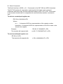
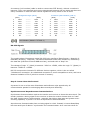
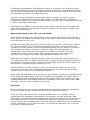
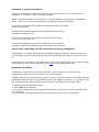
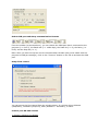
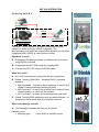
SAT-200 INTEGRATION It’s as easy as A, B, C Integration Partners & Applications SAT-202 Satellite Modem RS232 RS232 Microprocessor GSM / GPRS Modem or Sensor Device The GSM / GPRS modem is a highly flexible plug and play modem for direct and easy RS232 integration. The Microprocessor can either be a stand alone product or part of the integrated GSM / GPRS or other Sensor solution. How does it work? A – Programme the Microprocessor to interface with the device using RS232 protocols B – Programme the SAT-202 using the scripting SDK C – Connect the SAT-202 using the RS232 cable What do I need? A – SAT-202 User manual to determine the pin connections B – Global Tracking GDN 0559 – Scripting & API Command Interface. MM Command – to build an 84 bit message to send to the Global Tracking Message Handling System MR Command – to see if the terminal has a channel & the channel quality i.e. can it see the satellite MT Command – to check if the message has been sent C – Global Tracking SDK application and up-loader software – to programme the terminal with your bespoke functions What is the Message Content? A – The Message Payloads (84 bits) are as follows: Periodic report Message type 8 bits (0x20 for periodic report) Message count Latitude Longitude Speed Heading GPS status Scratchpad 7 Control bits & Checksum Sensor report Message type Message count Scratchpad 7 Scratchpad 8 Scratchpad 9 Scratchpad 10 Control bits & Checksum 4 bits (rolling number, incremented at each transmission) 21 bits 22 bits 8 bits 4 bits 1 bit 12 bits (least significant 12 bits of scratchpad 7 register) 4 bit 8 bits (0x21 for sensor report) 4 bits (rolling number, incremented at each transmission) 12 bits (least significant 12 bits) 32 bits 16 bits (least significant 16 bits) 8 bits (least significant 8 bits) 4 bit B – The scratchpad registers are written to by the microprocessor and the integrator should determine what the most appropriate data should be. C – To assist in this process the SAT-Manager and/or Uploader are available on the support site: http://support.satamatics.com/doc/portal/technical?action=technical&cat=program&srt=date&nam=So ftware%20Releases What are the basic Data Transfer Protocols? A – To send data to our SAT-202 terminal, Information/parameters from the microprocessor are to be written (via serial interface commands) to scratchpad registers within the satellite terminal (SAT-202). B – Data transfer handshake The SAT-202 will set a bit (RDY) in scratchpad register 6 to a 1 to indicate it is ready to receive data. The microprocessor will read RDY and send updated information when RDY is 1. Scratchpad registers 7 to 14 are available for writing information to. All scratchpad registers are 32 bits. At the end of the transfer, the microprocessor needs to write zero to scratchpad register 6, resetting RDY to 0. With RDY=0, the SAT-202 will process the data from the microprocessor and transmit via satellite. The SAT-202 will set RDY to 1 when it is ready to receive more data. C – Serial Commands The Serial Interface is 9600, n, 8, 1. Commands to the SAT-202 are ASCII characters. The SAT-202 echoes all commands, replacing the initial upper case command characters with lower case. Echoed responses always end in <LF><CR>. Commands to the terminal should wait for a response to be echoed before another command is sent. To write to a scratchpad register use: RW 06 nn hhhhhhhh<CR> Where: nn = 2 character ASCII hex representation of the register number. hhhhhhhh = 8 character ASCII hex representation of the 32 bit value to be stored in the register. Example: The terminal will respond with: RW 06 1F 1234ABCD <CR> rw 06 1F 12345ABCD<LF><CR> To read a scratchpad register use: RR 06 nn?<CR> The terminal will respond with: rr 06 nn hhhhhhhh<LF><CR> Tech Note: 3 easy steps to understand and control your RS232 devices Step 1: Understand RS-232 Connections & Signals DTE and DCE DTE stands for Data Terminal Equipment. A computer is a DTE. DCE stands for Data Communication Equipment. A modem is a DCE. DTE normally comes with a Male Connector, while DCE comes with a Female Connector. However, that is not always true. Use the simple way below to confirm: Measure Pin 3 and Pin 5 of a DB-9 Connector with a Volt Meter, if you get a voltage of -3V to -15V, then it is a DTE device. If the voltage is on Pin 2, then it is a DCE device. Note: The result for a DB-25 Connector is reversed (Please refer to DB-9 to DB-25 conversion table below). RS-232 Pinouts (DB-9) A male DB-9 connector viewed from the front. Reverse or back view of male connector for Female Connector. DTE Pin Assignment (DB-9) 1 DCD Data Carrier Detect 2 RxD Receive Data 3 TxD Transmit Data 4 DTR Data Terminal Ready 5 GND Ground (Signal) 6 DSR Data Set Ready 7 RTS Request to Send 8 CTS Clear to Send 9 RI Ring Indicator DCE 1 2 3 4 5 6 7 8 9 Pin Assignment (DB-9) DCD Data Carrier Detect TxD Transmit Data RxD Receive Data DSR Data Set Ready GND Ground (Signal) DTR Data Terminal Ready CTS Clear to Send RTS Request to Send RI Ring Indicator DB-9 to DB-25 Conversion DB-9 1 2 3 4 5 6 7 8 9 DB-25 8 3 2 20 7 6 4 5 22 DCD RxD TxD DTR GND DSR RTS CTS RI Function Data Carrier Detect Receive Data Transmit Data Data Terminal Ready Ground (Signal) Data Set Ready Request to Send Clear to Send Ring Indicator RS-232 Connections A straight-through cable is used to connect a DTE (e.g. computer) to a DCE (e.g. modem), all signals in one side connected to the corresponding signals in the other side in a one-toone basis. A crossover (null-modem) cable is used to connect two DTE directly, without a modem in between. They cross transmit and receive data signals between the two sides and there are many variations on how the other control signals are wired, below is one of them: 1 2 3 4 5 6 7 8 9 Straight-through (DB-9) (DTE) (DCE) DCD ------DCD RxD ------TxD TxD ------RxD DTR ------DSR GND ------GND DSR ------DTR RTS ------CTS CTS ------RTS RI ------RI 1 2 3 4 5 6 7 8 9 Crossover (Null-Modem) (DB-9) (DTE) (DTE) 1 DCD DCD 1 2 RxD ------TxD 3 3 TxD ------RxD 2 4 DTR ------DSR 6 5 GND ------GND 5 6 DSR ------DTR 4 7 RTS ------CTS 8 8 CTS ------RTS 7 9 RI RI 9 Null-Modem (Model: CVT-Null-1) RS-232 Signals RS-232 Logic Waveform (8N1) The graphic above illustrates a typical RS-232 logic waveform (Data format: 1 Start bit, 8 Data bits, No Parity, 1 Stop bit). The data transmission starts with a Start bit, followed by the data bits (LSB sent first and MSB sent last), and ends with a "Stop" bit. The voltage of Logic "1" (Mark) is between -3VDC to -15VDC, while the Logic "0" (Space) is between +3VDC to +15VDC. RS-232 connects the Ground of 2 different devices together, which is the so-called "Unbalanced" connection. An unbalanced connection is more susceptible to noise, and has a distance limitation of 50 ft (which is around 15 meters). Step 2: Learn about the Protocol A protocol is one or a few sets of hardware and software rules agreed to by all communication parties for exchanging data correctly and efficiently. Synchronous and Asynchronous Communications Synchronous Communication requires the sender and receiver to share the same clock. The sender provides a timing signal to the receiver so that the receiver knows when to "read" the data. Synchronous Communication generally has higher data rates and greater errorchecking capability. A printer is a form of Synchronous Communication. Asynchronous Communication has no timing signal or clock. Instead, it inserts Start/Stop bits into each byte of data to "synchronize" the communication. As it uses less wires for communication (no clock signals), Asynchronous Communication is simpler and more costeffective. RS-232/RS-485/RS-422/TTL are the forms of Asynchronous Communications. Drilling Down: Bits and Bytes Internal computer communications consists of digital electronics, represented by only two conditions: ON or OFF. We represent these with two numbers: 0 and 1, which in the binary system is termed a Bit. A Byte consists of 8 bits, which represents decimal number 0 to 255, or Hexadecimal number 0 to FF. As described above, a byte is the basic unit of Asynchronous communications. Baud rate, Data bits, Parity, and Stop bit RS-232 Logic Waveform (8N1) The baud rate is the communication speed that measures the number of bit transfers per second. For example, 19200 baud is 19200 bits per second. Data bits are a measurement of the actual data bits in a communication packet. For example, the above graphic shows eight (8) data bits in a communication packet. A communication packet refers to a single byte transfer, including Start/Stop bits, Data bits and Parity. If you are transferring a standard ASCII code (0 to 127), 7 data bits are enough. If it is an extended ASCII code (128 to 255), then 8 data bits are required. Parity is a simple way to error-check. There are Even, Odd, Mark and Space indicators. You can also use no parity. For Even and Odd parity, the serial port sets the parity bit (the last bit after the data bit) to a value to ensure that the data packet has an Even or Odd number of logic-high bits. For example, if the data is 10010010, for Even parity, the serial port sets the parity bit as 1 to keep the number of logic-high bits Even. For Odd parity, the parity bit is 0 so that the number of logic-high bits is Odd. Mark parity simply sets the parity bit to logic-high and Space sets the parity bit to logic-low, so that the receiving party can determine if the data is corrupted. Stop bits are used to signal the end of a communication packet. This also helps to synchronize different clocks on the serial devices. Handshaking (Flow Control) Handshaking is also called "Flow Control". The main purpose of Handshaking is to prevent receiver overloading. By using Handshaking signals, receivers will be able to tell the sending device to pause data transmission if the receiver is overloaded. There are three types of handshaking: Software handshaking, Hardware handshaking and Both. Software handshaking uses two control characters: XON and XOFF. The receiver sends these control characters to pause transmitter during communication. XON is decimal 17 and XOFF is decimal 19 in the ASCII chart. The drawback of Software handshaking is that these two control characters can not be used in data. This is quite important when you are transmitting Binary data as you might need to use these two codes in your data. Hardware handshaking makes use of actual hardware lines, such as RTS/CTS, DTR/DSR, and DCD/RI (for modem). In DTE/DCE communication, RTS (Request to Send) is an output on the DTE and input on the DCE. CTS (Clear to Send) is the answering signal coming from the DCE. Before sending a data, the DTE asks permission by setting its RTS output to high. No data will be sent until the DCE grants permission by using the CTS line. The DTE uses the DTR (Data Terminal Ready) signal to indicate it is ready to accept information, whereas the DCE uses the DSR signal for the same purpose. DTR/DSR are normally ON or OFF for the whole connection session (e.g. Off-hook), while RTS/CTS are ON or OFF for each data transmission. DCD (Data Carrier Ready) is used by the modem when a connection has been established with remote equipment, while RI (Ring Indicator) is used by the modem to indicate a ring signal from telephone line Data formats (Binary, Hex, Dec, Oct, and ASCII) Serial devices use Binary for communication, which consists of just two unique numbers: 0 and 1. Binary is the Base-2 numbering system. One byte of data consists of 8 binary digits, from 0000 0000 to 1111 1111. Hexadecimal is the base-16 system, which consists of 16 numbers: 0 to 9 and the letters A to F (decimal number 15). The Hexadecimal numbering system is useful because it can represent every byte as two consecutive hexadecimal digits, and it is easier for humans to read Hexadecimal numbers than Binary numbers. Most of the manufacturers use Hexadecimal in their protocol documentation. It is simple to convert a value from Hexadecimal to Binary. Just translate each Hexadecimal digit into its 4-bit binary equivalent. E.g. Hexadecimal number F3 equals Binary number 1111 0011. Octal refers to the base-8 numbering system, which uses just eight unique symbols (0 to 7). Programmers often use Octal format because it is relatively easy for people to read and can easily be translated into binary format: each Octal digit represents 3 binary digits. E.g. Octal number 73 equals to Binary number 111 011. Decimal refers to numbers in base 10, which is the numbering system we use most in everyday life. It's not as easy as Hexadecimal and Octal to converter Decimal to Binary number, but it is easier for us to understand Decimal. ASCII (American Standard Code for Information Interchange) is a character encoding based on the English alphabet. ASCII codes (both readable and unreadable) are widely used in communications, such as Modem communications. Letters A to Z and numbers 0 to 9 are readable ASCII codes. Some ASCII codes are unreadable, such as the control codes: XON and XOFF, which are used in Software flow control. Checksum Many serial protocols use checksum (additional bytes added at the end of the data string) to check the data integrity, as errors might occur during data transmission. There are many types of checksum, from the simplest uses of it in Modula or BCC to sophisticated CRC calculation. Using Modula as an example, we learn that before data transmission, the sender adds all command bytes together then mod it by 255 (decimal) to get an additional byte. This is to be added at the end of the command string. When the receiver receives the command string, it will first check the added byte to see whether data remain unchanged or not. If that is the case, it will accept the data, and if not, it will ask the sender to resend the data. Examples of protocol commands A protocol command is a data string sent from one serial device (e.g. a Computer) to another (i.e. a Modem). Here are some examples: ASCII command example: ATI1<CR><LF> to query Modem manufacturer's information. (Note: <CR><LF> are the control codes: Carriage Return and Line Feed) Convert the command string above to Hexadecimal and it becomes: 41 54 49 31 0D 0A Convert the command string above to Decimal and it becomes: 065 084 073 049 013 010 Convert the command string above to Octal and it becomes: 101 124 111 061 015 012 Convert the command string above to Binary and it becomes: 01000001 01010100 01001001 00110001 00001101 00001010 Step 3: Start controlling your RS-232 devices by using 232Analyzer 232Analyzer is an Advanced Serial Port (protocol) Analyzer software, which allows you to control/debug, monitor/sniff serial devices (RS-232/RS-485/RS-422/TTL) right from your PC. 232Analyzer is a shareware, the FREE version has some limitation but is more than enough to test and control your serial devices. Click here to download a FREE copy. Checksum calculation 232Analyzer comes with a Checksum calculator, which allows you to calculate the complicated checksum byte in seconds, here is an example: Suppose that you are controlling a projector, and the projector protocol uses xOR to get the additional checksum byte, the command string to turn ON the projector is: "1A 2B 3C" plus the Checksum byte. Use the following procedures to calculate the Checksum byte: 1. Select Hex as an operands format 2. Select xOr as an operator 3. Key in the command string and append a comma (,) after each byte of command code: e.g. 1A,2B,3C, 4. Click on the "Calculate" button and you will get the result of 0D (0 is omitted) Select COM port and Setup communication formats From the toolbar (as shown above), you can choose the COM port that is connected to the projector (i.e. Port 5), the Baud rate (i.e. 19200 bps), the Data bit (i.e. 8), the Parity (i.e. Even) and the Stop bit (i.e. 1). Note: After you have set up the correct communication formats (they must match with the projector's COM port settings), click on the "Connect" button on the left to activate the COM port. Setup Flow control You can set up the flow control from the window above. It could be either Software (XON/XOFF), Hardware (RTS/CTS), Both (Software + Hardware), or None. Control your RS-232 devices 1) Control / Monitor Line States 232Analyzer allows you to control / monitor line states of your COM ports. 1. Line states of RTS and DTR will be toggled when the respective LED is clicked, you can use a voltage-meter to verify the changes, you should get +6V to +15V when the line state is ON, and -6V to -15V when the line state is OFF. 2. Other line states can be monitored through the Virtual LEDs, such as RX, TX, DSR, CTS, DCD and RI. 2) Send / Receive commands Use the above example to control a projector (turn ON the projector), key in the complete command string "1A,2B,3C,0D," into the Send_Command_Pane as shown above (note: You need to add a "," sign after each command code), and then click on the "Send" button...