1
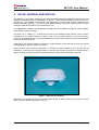
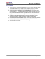
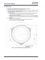
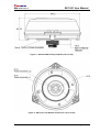
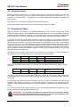
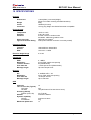
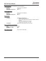
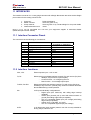
SAT-201
User Manual
Document No: MAN-0019
Issue No:
2
Dated:
16 June 2005
SAT-201 User Manual
MAN-0019 Issue 2
COPYRIGHT
Copyright in this document is vested in Satamatics Ltd. This document is issued in confidence for the
purpose only for which it is supplied. It must not be reproduced in whole or in part except with the
consent in writing of Satamatics Ltd and then only on the condition that this notice is included in any
such reproduction.
Revision History
Date
Issue
Comments
19 April 2005
1
16 June 2005
2
Initial Issue.
3.1 Minor changes to European Compliance Statement
11.3 Included warning regarding IO devices default
state
14. Minor Change to Product Information
Page 2 of 22
© Satamatics Ltd.
SAT-201 User Manual
MAN-0019 Issue 2
CONTENTS
1
1.1
1.2
1.3
1.4
LEGAL INFORMATION................................................................................................................4
Notice .......................................................................................................................................4
Limited Warranty......................................................................................................................4
Limitation of Warranty ..............................................................................................................4
Governing Law .........................................................................................................................4
2.1
SAFETY WARNINGS ...................................................................................................................5
General Safety Warnings.........................................................................................................5
3.1
3.2
3.3
3.4
REGULATORY AND TYPE APPROVAL INFORMATION ..........................................................6
European Compliance .............................................................................................................6
FCC Authorisation....................................................................................................................6
INMARSAT Type Approval ......................................................................................................6
Limitations on intended operating environment .......................................................................6
2
3
4
SAT-201 GENERAL DESCRIPTION ...........................................................................................7
5
5.1
5.2
5.3
5.4
5.5
5.6
INSTALLATION............................................................................................................................8
Power Requirements ...............................................................................................................8
Cable........................................................................................................................................8
Location....................................................................................................................................9
Mounting ................................................................................................................................10
Applying Power ......................................................................................................................12
Operational Check .................................................................................................................12
6
FUNCTIONALITY .......................................................................................................................13
7
MODES OF OPERATION...........................................................................................................13
8
FACTORY DEFAULTS...............................................................................................................13
9
9.1
9.2
MAINTENANCE AND SUPPORT INFORMATION....................................................................14
Cleaning .................................................................................................................................14
Technical Support and Information ........................................................................................14
10
SPECIFICATIONS ......................................................................................................................15
11
INTERFACES .............................................................................................................................17
11.1
Interface Connector Pinout ...............................................................................................17
11.2
Interface functions............................................................................................................17
11.3
General Purpose I/O .........................................................................................................18
12
INTERPRETING THE INDICATOR ............................................................................................19
13
APPENDIX – A ...........................................................................................................................20
13.1
CE Declaration of Conformity ...........................................................................................20
14
Product Information..................................................................................................................21
© Satamatics Ltd.
Page 3 of 22
SAT-201 User Manual
1
MAN-0019 Issue 2
LEGAL INFORMATION
1.1 Notice
Information in this document is subject to change without notice. Satamatics Ltd. makes no warranty of any kind
with regards to this material, including, but not limited to, the implied warranties of merchantability and fitness for
purpose. Satamatics Ltd. shall not be liable for errors contained herein or for incidental or consequential damages
in connection with the use of this material. No part of this document may be photocopied, reproduced, or
translated to another language without prior written consent of Satamatics Ltd. The Satamatics logo is a
registered trademark of Satamatics Ltd. All other trademarks belong to their respective proprietors.
1.2 Limited Warranty
Satamatics warrants that the SAT-201 product will be free from defects in material and workmanship for a period
of one (1) year from date of purchase. During the warranty period Satamatics Ltd will, at its option, either repair
or replace products that prove to be defective. If a defect exists, at its option Satamatics Ltd will repair the
product at no charge, using new or refurbished replacement parts, or exchange the product with a product that is
new or which has been manufactured from new or serviceable used parts and is at least functionally equivalent to
the original product. A replacement product assumes the remaining warranty of the original product or 90 days,
whichever is the longer for you. All Hardware (or part thereof) that is replaced by Satamatics Ltd shall become
the property of Satamatics Ltd upon replacement. Satamatics does not warrant that the operation of the
equipment or firmware will be uninterrupted or error free.
For warranty service or repair the product must be returned to a service facility designated by Satamatics Ltd
quoting the information contained in Section 14. Failure to do so could invalidate or delay any warranty repair.
1.3 Limitation of Warranty
The foregoing warranty shall not apply to defects resulting from improper or inadequate maintenance by the
Buyer, Buyer-supplied software (scripts) or interfacing, unauthorized modification or misuse, operation outside of
the environmental specifications for the product, or improper installation.
EXCEPT FOR THE ONE (1) YEAR LIMITED WARRANTY SPECIFIED HEREIN, THE PRODUCT IS PROVIDED “AS-IS”
WITHOUT ANY WARRANTY OF ANY KIND INCLUDING, WITHOUT LIMITATION, ANY WARRANTY OF
MERCHANTABILITY, FITNESS FOR A PARTICULAR PURPOSE AND NON-INFRINGEMENT.
If ANY IMPLIED
WARRANTY CANNOT BE DISCLAIMED IN ANY TERRITORY WHERE A PRODUCT IS SOLD, THE DURATION OF SUCH
IMPLIED WARRANTY SHALL BE LIMITED TO NINETY (90) DAYS. EXCEPT AS EXPRESSLY COVERED UNDER THE
LIMITED WARRANTY PROVIDED HEREIN, THE ENTIRE RISK AS TO THE QUALITY, SELECTION AND PERFORMANCE
OF THE PRODUCT IS WITH THE PURCHASER OF THE PRODUCT.
TO THE MAXIMUM EXTENT PERMITTED BY LAW, SATAMATICS LTD IS NOT LIABLE UNDER ANY CONTRACT,
NEGLIGENCE, STRICT LIABILITY OR OTHER LEGAL OR EQUITABLE THEORY FOR ANY LOSS OF USE OF THE
PRODUCT, INCONVENIENCE OR DAMAGES OF ANY CHARACTER, WHETHER DIRECT, SPECIAL, INCIDENTAL OR
CONSEQUENTIAL (INCLUDING, BUT NOT LIMITED TO, DAMAGES FOR LOSS OF GOODWILL, WORK STOPPAGE,
COMPUTER FAILURE OR MALFUNCTION, LOSS OF INFORMATION OR DATA CONTAINED IN, STORED ON, OR
INTEGRATED WITH ANY PRODUCT RETURNED TO SATAMATICS LTD FOR WARRANTY REPAIR) RESULTING FROM
THE USE OF THE PRODUCT, RELATING TO WARRANTY SERVICE, OR ARISING OUT OF ANY BREACH OF THIS
LIMITED WARRANTY, EVEN IF SATAMATICS LTD HAS BEEN ADVISED OF THE POSSIBILITY OF SUCH DAMAGES.
THE SOLE REMEDY FOR A BREACH OF THE FOREGOING LIMITED WARRANTY IS REPAIR OR REPLACEMENT OF
THE DEFECTIVE OR NON-CONFORMING PRODUCT.
1.4 Governing Law
The laws of England and Wales shall govern this one (1) year warranty. Some countries do not allow the
exclusion or limitation of incidental or consequential damages or exclusions or limitations on the duration of
implied warranties or conditions. The above limitations may not therefore apply to you. This warranty gives you
specific legal rights, and you may also have rights that vary by country.
Page 4 of 22
© Satamatics Ltd.
MAN-0019 Issue 2
2
SAT-201 User Manual
SAFETY WARNINGS
BEFORE APPLYING POWER TO THE EQUIPMENT the user must read all instructions.
If in any doubt, consult suitably trained service personnel.
2.1 General Safety Warnings
No user serviceable parts inside. Refer servicing to qualified service personnel.
The equipment contains no replaceable fuses.
Retain the safety and operating instructions for future reference.
Observe all warnings on the equipment and in the operating instructions.
Follow all operating and user instructions.
Connect the equipment to a power supply only of the type described in the operating
instructions or marked on the equipment.
The unit should be located away from power lines.
Maximum permissible exposure (MPE) limits – This equipment complies with FCC (OET
bulletin 65) general population/uncontrolled exposure limits as applied to RF energy from a
Mobile device. (A mobile device being defined as a transmitting device designed to be used
in other than fixed locations and to be generally used in such a way that a separation
distance of at least 20 centimetres is normally maintained between the transmitter's
radiating structures and the body of the user or nearby persons.)
© Satamatics Ltd.
Page 5 of 22
SAT-201 User Manual
3
MAN-0019 Issue 2
REGULATORY AND TYPE APPROVAL INFORMATION
3.1 European Compliance
The equipment is designed, tested and declared to conform to the following European directives and
standards:
1999/5/EC (CE mark - R&TTE) [includes directives 89/336/EEC (EMC) and 73/23/EEC
(LVD)]
Relevant Standards:
EN301 489-20 v1.2.1(2002-11)
EN 60950-1:2001
ETSI EN 301 426 v1.2.1(2001-10)
ETSI EN 301 489-1 v1.4.1
EMC Testing
Electrical Safety (R&TTE)
Radio Approval
The Declaration of Conformity can be found at APPENDIX – A.
3.2 FCC Authorisation
The following information is provided on the device covered in this document in compliance with FCC
regulations:
Model number: SAT-201
Company Name: Satamatics Ltd.
Gloucester Road
Tewkesbury
GL20 5TT
UK
Also see MPE statement in Section 2.1.
3.3 INMARSAT Type Approval
The SAT-201 has been certified for operation on the Inmarsat Network (Inmarsat Certificate Number
DST002).
3.4 Limitations on intended operating environment
The SAT-201 can be used in a wide range of control and monitoring applications. When third party
equipment is attached, such third party equipment and all cabling must be of suitable design and
installation to ensure that the overall system complies with the requirements of the appropriate CE
directives.
Guidance notes for the installation and use of the SAT-201 must be strictly followed.
Satamatics exercise due diligence to ensure that the equipment is suitable for use in stated
applications, but ultimate responsibility for the compliance of a complete system must rest with the
prime contractor at a site where local conditions may require additional EMC precautions be taken.
WARNING: Changes or modifications to this unit not expressly approved by the party
responsible for compliance could void the user's authority to operate this equipment.
Page 6 of 22
© Satamatics Ltd.
SAT-201 User Manual
MAN-0019 Issue 2
4
SAT-201 GENERAL DESCRIPTION
The SAT-201 is a compact, single unit, low data rate satellite terminal, designed to operate over the
INMARSAT satellites using the INMARSAT D+ protocol. With an integral GPS receiver, the SAT-201
provides low cost satellite communications for applications such as asset tracking, telematics and
SCADA exception reporting. If you do not need battery backup, solar panel power inputs or 4-20mA
analogue output drivers then this is the solution for you.
Four INMARSAT satellites provide Global Coverage with each satellite covering an ‘Ocean Region’
(IOR, AOR-E, AOR-W or POR).
On power on or ‘waking up’, a terminal first tunes to the Bulletin Board channel, which contains
information on the traffic channels currently in use. From the traffic channel / service ID mapping
posted on the Bulletin Board, the terminal determines on which traffic channel to expect its messages,
and re-tunes to this channel.
Data rate for the forward channel (to terminal) is approximately 9 user bits per second, with typical
message delivery latency of about 3 minutes.
Return channel (from terminal) information is returned in bursts containing up to 80 user bits of
information. The data rate is approximately 10 user bits per second, with typical message delivery
latency of about 30s (assuming the terminal has already synchronised to the traffic channel).
Figure 1 – SAT-201 D+ Terminal
Mounting is via 3x M4 (No. 8) bolts or central M25 thread on base. Cable entry is from the centre
base, connector details are given in section 11.
© Satamatics Ltd.
Page 7 of 22
SAT-201 User Manual
5
MAN-0019 Issue 2
INSTALLATION
IMPORTANT: Installation and service should only be carried out by suitably qualified
service personnel.
Local working practices and regulations for wiring and installations must be adhered to at all times.
5.1 Power Requirements
The equipment is powered from an external DC supply of 9.6V to 32V. The DC supply must be
capable of providing a maximum VA of 9.6W, for example 1A @ 9.6V or 0.3A @ 32V.
External power is connected via the 12-way connector (see section 11 for connector details and pin
connections)
When installing the SAT-201, adequate circuit protection must be provided as required by local
regulations.
IMPORTANT: If connecting to an external battery, the SAT-201 requires an external
fast acting fuse connected in series with the +ve supply at the battery end of the
cable.
Input voltage
9.6 to 32 VDC
Fuse Rating
1A
Minimum wire gauge
24 AWG (7/0.2)
IMPORTANT: If an external AC/DC Adaptor is used to power the equipment, it must
meet the requirements of EN 60950-1. The output of the Adaptor must also meet the
SELV limits of EN 60950-1.
5.2 Cable
It is recommended that cable routing is planned and operation tested before committing to a
permanent installation. The maximum cable diameter must not exceed 7mm.
As standard, the SAT-201 is supplied without cable or mating connector. (See section 11 for
mating connector details). Suitable cables and/or connectors can be purchased separately
from your equipment supplier or authorised dealer.
When routing the cable avoid sharp edges and pinches.
Be aware of the minimum static bend radius of the cable.
Mechanical pressure on the cable may cause loss of functionality or even a short circuit and
subsequent damage to the terminal.
Use only shielded cables for connecting to peripherals. Using shielded cables ensures that
the appropriate EMC classifications are maintained.
Page 8 of 22
© Satamatics Ltd.
MAN-0019 Issue 2
SAT-201 User Manual
5.3 Location
The SAT-201 is only weatherproof if the interface connector is correctly mated with a Bulgin
400 series Buccaneer connector. Please consult your dealer if you are in any doubt.
The SAT-201 should be located with an unobstructed, clear view of the sky.
The SAT-201 should be mounted on a flat horizontal surface.
Consider the position of the satellites. The Inmarsat satellites are in geostationary orbits
above the equator. (i.e., in the Northern hemisphere the satellites are located to the South;
in the Southern hemisphere the satellites are located to the North.) The further away from
the Equator the SAT-201 is, the lower the degree of elevation will be above the horizon.
If you plan to install the SAT-201 in a partially enclosed environment, test operation before
committing to a permanent installation.
On vehicles, the SAT-201 should be located on the highest point possible, free from
obstructions and safe from damage during normal operation of the host vehicle.
For installations exposed to shock and/or vibration, use a mounting scheme that isolates the
unit from the excessive shock and/or vibration.
Choose a location that is not near radar installations, other satellite communication
equipment, and/or microwave dishes to prevent RF jamming.
Avoid mounting on hot surfaces.
© Satamatics Ltd.
Page 9 of 22
SAT-201 User Manual
MAN-0019 Issue 2
5.4 Mounting
If possible, try the installation before drilling any holes or fixing cable.
Record the ISN number of the unit for future reference.
The SAT-201 may be mounted by utilising either the three outer M4 mounting holes (Figure
2) or the M25 thread on the base (Figure 3).
If using the three outer mounting holes (recommended for installations exposed to shock
and/or high vibration):
Drill a central 40mm hole to pass the connector and base mounting thread through.
Position the SAT-201 and mark the location of the three mounting holes.
Drill three 4.5mm mounting holes.
Secure the SAT-201 in place using M4 (No.8) screws and nuts - Do not over tighten.
Alternatively, secure using screws appropriate to the mounting surface - Do not over
tighten.
If using the M25 base mounting thread:
Drill a 26mm hole to pass the connector and mounting thread through.
Secure using M25 nut - Do not over tighten.
Figure 2 - SAT-201 M4 Drilling Diagram (not to scale)
Page 10 of 22
© Satamatics Ltd.
MAN-0019 Issue 2
SAT-201 User Manual
Figure 3 - SAT-201 M25 Drilling Template (not to scale)
Figure 4 - SAT-201 Foam Washer Dimensions (not to scale)
© Satamatics Ltd.
Page 11 of 22
SAT-201 User Manual
MAN-0019 Issue 2
5.5 Applying Power
Before connecting the SAT-201 to an external voltage source ensure that the polarity is correct and
the voltage source (at the input to the SAT-201) is between 9.6V and 32V. See Section 11.1 for
connector pin out description. See Section 5.1 for further details and requirements regarding the
power source.
Check the circuit, in particular fuses and/or circuit protection devices.
Always ensure that the ground connection is connected before power is applied.
5.6 Operational Check
When the SAT-201 first powers up, it includes instructions to start its GPS receiver. After it has
acquired its GPS position, it then identifies the best Ocean Region to use and proceeds through the
sequence of states referred to in Section 12. If, for some reason, the unit is not able to obtain a valid
GPS reading after two minutes, it will follow the sequence using the default Ocean Region (AORE).
If you wish to check the overall system operation, it will be necessary to ensure that the terminal is
activated on a known gateway and that you have access to the application running there, so that you
can view the received data. If you do not have access to an application of your own, it is possible to
set up your terminal on one of the Satamatics websites in order to perform end-to-end testing. Please
consult your service provider for details of the activation that has been put in place for your terminal. If
you do not have access to the application, it is still possible to check the local operation of the terminal
and its installation by using the following sequence. In this case it will then be necessary to check the
application part of the system later.
With the SAT-201 in position, apply power to the unit and monitor the indicator. Initially it will either be
off or will be in the D+ off state, and will then cycle through the following states.
RED
RED
GREEN
GREEN
OFF
OFF
GREEN
ORANGE
OFF
GREEN
RED
GREEN
OFF
OFF
RED
OFF
D+ Off
Acquiring Bulletin Board
Demodulating Bulletin Board
Acquiring Traffic Channel
Once it has acquired the traffic channel, the unit will cycle through the following two states in normal
operation.
GREEN
GREEN
GREEN
OFF
GREEN
OFF
OFF
OFF
Demodulating Traffic
Channel
Idle part of TC Frame
The terminal will transmit its initial report (LED turns orange for ten seconds) after successfully
completing the above states. The total process to transmission will normally take between three and
six minutes.
Providing that your terminal has been activated and set up within an application, the data will be
available within about one minute of the actual transmission, although this is dependent on the
operation of the software being used by your service provider as well as the link to the Satamatics
server.
Your service provider will be able to supply you with further details regarding the normal use of the
terminal, as well as scripts and forward channel use.
IMPORTANT: The foregoing only applies to terminals that are set at Factory Default
and with the default script installed (see Section 8). If you are unsure about the state
of your terminal, you should consult your service provider.
Page 12 of 22
© Satamatics Ltd.
MAN-0019 Issue 2
6
SAT-201 User Manual
FUNCTIONALITY
For full functional details on the SAT-201 contact your authorised dealer.
7
MODES OF OPERATION
SLEEP
Extremely low power mode. D+ and GPS functions are switched off. IDLE mode is entered
periodically so that external voltage can be checked.
IDLE
In certain circumstances, the terminal will enter IDLE mode. For example, where GPS is not
required and the current Traffic Channel frame contains no forward messages addressed to the
unit.
GPS ONLY
Similar to IDLE mode except that GPS is active, enabling the terminal to monitor its position and
compare, for example, against a Geofence.
STATIC
Normal D+ operation where the terminal cycles between RECEIVE, IDLE and TRANSMIT as
appropriate. GPS is not enabled.
MOBILE
Similar to STATIC mode except that GPS is also enabled.
8
FACTORY DEFAULTS
The terminal is shipped with Factory Defaults set. When power is initially applied, the script timer,
alarm and operation definitions are cleared; the terminal then powers up, acquires the GPS position
and tunes to the best ocean region for the terminal location. Once the terminal has acquired the D+
satellite signal it transmits a single position report burst.
© Satamatics Ltd.
Page 13 of 22
SAT-201 User Manual
9
MAN-0019 Issue 2
MAINTENANCE AND SUPPORT INFORMATION
9.1 Cleaning
Dust and finger marks can be removed using a soft damp cloth. Avoid using domestic cleaning
products.
9.2 Technical Support and Information
For technical support, product queries and information please contact your equipment supplier or
authorised dealer.
Authorised dealers and general information about Satamatics products and services can be found at:
http://www.satamatics.com
Page 14 of 22
© Satamatics Ltd.
SAT-201 User Manual
MAN-0019 Issue 2
10 SPECIFICATIONS
Physical
Dimensions
Weight
Colour
Connector
112mm(diam) x 45.75mm(height)
(Does not include mounting threads/extensions)
350g
UN0332 (Coconut)
12 way plug. Bulgin 400 Series Buccaneer compatible
Environmental
Temperature
Humidity
Vibration
Shock (survival)
Ingress Protection Rating
-40ºC to +70ºC
≤ 95% @ +40ºC
5-20Hz: 1.92m2s-3 random noise
20-500Hz: -3dB octave random noise
Half sine 6ms, 300ms-2
IP66 (when interface connector is correctly mated)
Frequency Range
Transmit
Receive
GPS
Elevation Angle Range
1626.5 MHz to 1660.5 MHz
1525.0 MHz to 1559.0 MHz
1575.42 ± 1.0 MHz
0º to 90º
Transmitter
EIRP
Modulation
Tx burst duration
User data rate
Message length
0 - 9dBW
2 level FSK, 256Hz tone spacing
8s (Global Beam)
~10 bits per second (Global beam)
Up to 84 bits per burst
Receiver
G/T
Modulation
User data rate
Message length
≥ -25dB/K at EL = 30º
32-ary FSK, 20Hz tone spacing
~9 bits per second
Up to 1000 bits
Channels
Time To First Fix (Typical)
Cold start
Hot start
Accuracy (SA Off)
Position (CEP, 2D)
Altitude
Dynamic capability
Velocity
Acceleration
Maximum update rate
12
GPS
© Satamatics Ltd.
45s
<8s (GPS was off for less than 2 hours)
4m (Typical)
maximum 18000m
maximum 515m/s
≤4g
1s
Page 15 of 22
SAT-201 User Manual
MAN-0019 Issue 2
GPS test interface (not available during normal operation)
Interface
Baud rate
Parity/data bits/stop bits
Asynchronous serial RS232
38400 bps
N,8,1
Control & Monitoring
Interface
Baud rate
Parity/data bits/stop bits
Asynchronous serial RS232
9600 bps
N,8,1
Data Interfaces
2 x Inputs
2 x Outputs
Individually configurable as:
o
Digital input (32V maximum)
o
Switch input (internal pull up used with external switch to
ground)
o
SAT-101 compatible I/O (low voltage)
o
Analog input (12 bit ADC, 0 to 2.5V)
Open drain output (250mA max sink current)
Power Consumption (Typical@12V)
Sleep
Receive (incl. GPS)
Transmit
Power Supply Voltage
Page 16 of 22
0.5mW
1.5W
6W
9.6V to 32V ‘smoothed’ DC
© Satamatics Ltd.
SAT-201 User Manual
MAN-0019 Issue 2
11 INTERFACES
The interface connector is a 12 way plug that mates with a Bulgin Buccaneer 400 series socket. Bulgin
part numbers for the mating connector are:
1.
2.
3.
4.
Connector:
Solder contacts:
Crimp contacts:
Insertion/extraction tool:
PX0410/12S/6570
SA3179/1 (pack of 10)
SA3179 (pack of 10). Contact Bulgin for crimp tool details
13027
Items 1,2 & 4 can be purchased as a kit from your equipment supplier or authorised dealer
(Satamatics part number: 00925)
11.1 Interface Connector Pinout
The connector has the following pin connections:
Pin
1
2
3
4
5
6
7
8
9
10
11
12
Function
0V (cable screen)
Voltage In (VIN+)
0V (VIN-)
OUT2
OUT1
IN2
IN1
Rx
Tx
0V (VIN-)
Rx GPS
Tx GPS
Cable colour code
(if supplied by Satamatics)
[Screen]
Red
Orange
Yellow
Green
Blue
Purple
Grey
White
Black
Brown
Pink
11.2 Interface functions
VIN+, VIN-
External power input – 9.6V to 32V
Tx, Rx
RS232 serial control/data interface transmit (Tx) and receive (Rx) lines
o
9600bps, asynchronous, optional parity
o
Control function – for configuring the unit
o
Data function – for message input/output
Tx GPS, Rx GPS
RS232 serial GPS test interface transmit (Tx) and receive (Rx) lines.
38400bps, asynchronous, optional parity. Used for software download.
Not available during normal operation.
INn
2 off inputs individually configurable as:
o
Digital input (32V maximum) with falling edge interrupt
capability
o
Switch input (internal pull up used with external switch to
ground) with falling edge interrupt capability
o
SAT-101 compatible digital input (low voltage) with falling
edge interrupt capability
o
Analog input (12 bit ADC, 0 to 2.5V)
o
SAT-101 compatible digital output (low voltage)
OUTn
2 off digital open drain outputs (250mA max sink current) suitable for
driving relays, indicators etc.
© Satamatics Ltd.
Page 17 of 22
SAT-201 User Manual
MAN-0019 Issue 2
11.3 General Purpose I/O
Figure 5 shows a conceptual drawing of one of the general purpose inputs (INs).
3k9 Ohms
Switch input pull up
Digital in
Digital out
High voltage Digital in
Digital in falling edge interrupt
High voltage Digital in falling edge interrupt
Analogue in
10k Ohms
INs
Figure 5 SAT-201 general purpose Input block diagram
Figure 6 shows a conceptual drawing of one of the general purpose Outputs (OUTs).
OUTs
Open drain
0V (Vin-)
Figure 6 SAT-201 output block diagram
IMPORTANT: The factory default configuration disables the SAT-201 outputs
OUT1 and OUT2. To use these outputs the user must ensure that they are
configured as open drain outputs. Failure to do so will cause unexpected results.
Page 18 of 22
© Satamatics Ltd.
SAT-201 User Manual
MAN-0019 Issue 2
12 INTERPRETING THE INDICATOR
A single status indicator is provided on the SAT-201. The indicator goes through 4 states every 2
seconds generating the patterns in the table below
State 1
RED
RED
RED
GREEN
GREEN
GREEN
GREEN
ORANGE
State 2
RED
OFF
OFF
GREEN
ORANGE
GREEN
OFF
ORANGE
State 3
RED
OFF
GREEN
RED
GREEN
GREEN
OFF
ORANGE
State 4
RED
OFF
OFF
RED
OFF
OFF
OFF
ORANGE
Meaning
Fault
D+ OFF
Acquiring Bulletin Board
Demodulating Bulletin Board
Acquiring Traffic Channel
Demodulating Traffic Channel
Idle part of TC Frame
Transmitting
GREEN
RED
ORANGE
OFF
Software download in progress
Normally, from power on, the indicator will go from flashing red (D+ OFF) through to flashing green as
the SAT-201 first acquires the Bulletin Board and subsequently the Traffic Channel. From power on to
demodulating the Traffic Channel may take up to 7 minutes.
NOTE: The indicator can be disabled (off state) or enabled via script control. The indicator may
therefore not come on when power is applied. Contact your authorised dealer for details of any
script that may have been programmed into the SAT-201.
© Satamatics Ltd.
Page 19 of 22
SAT-201 User Manual
MAN-0019 Issue 2
13 APPENDIX – A
13.1 CE Declaration of Conformity
Page 20 of 22
© Satamatics Ltd.
SAT-201 User Manual
MAN-0019 Issue 2
14 PRODUCT INFORMATION
It is essential that the following information be completed at the time of installation/purchase to ensure
that any future warranty claims are dealt with as expeditiously as possible.
DATE OF PURCHASE:
PURCHASED FROM:
SAT 201 ISN:
D
S
T
0
0
2
SAT 201 SERIAL NUMBER:
IMPORTANT: PLEASE KEEP IN A SAFE PLACE FOR FUTURE REFERENCE
NOTES:
Dealer:
© Satamatics Ltd.
Page 21 of 22
Satamatics Ltd
Corporate Head Office
Tel: +44 (0)1684 278610
Fax: +44 (0)1684 278611
[email protected]
www.satamatics.com
Satamatics USA
Tel: +1 877 SAT MATD
Tel: +1 877 728 6283
[email protected]
www.satamaticsUSA.com