1
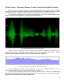
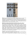
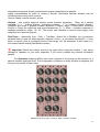
SpectrumWorx The Manual version 1.1 Edited by Scot Solida, The Electronic Garden License Agreement By purchasing this package, you are hereby granted the right to use this copy of this SOFTWARE, subject to the following restrictions: You may use SOFTWARE only on one computer with the exception of multi user license. You may not copy, or distribute any copies of this SOFTWARE or documentation, with the exception of copies made for back-up purposes. We still retain all rights to this SOFTWARE, meaning that by purchasing this software you can use it, but we still own the code, algorithms, designs, copyrights and anything else related to this software. You agree not to reverse engineer this product. You understand that this software may not be free of bugs or errors. We’ve done our best to make sure that the software is bug-free, but sometimes bugs happen. We are not liable for any damage caused by this software, whether it’s trashed files, or trashed recording sessions! We don’t expect this to happen, but you can’t be too careful. Back-up your data regularly! That said, we want you to be happy with this software. If you have a problem with this product, tell us, and we will try to correct the problem. IN ANY CASE, OUR LIABILITY IS LIMITED TO THE AMOUNT THAT YOU PAID FOR THIS SOFTWARE. Term of the Agreement This agreement is effective until terminated by you or us. You may terminate the agreement at any time by notifying us and destroying all copies of the manual, and erasing SOFTWARE from all readable media, whether on-line or on archival copies. In the event of breach of any of the terms of this agreement, you shall pay the attorney’s fees that are reasonably necessary to enforce the agreement plus resulting damages. Limited Warranty and Disclaimer THE SOFTWARE AND ACCOMPANYING MATERIALS ARE PROVIDED «AS IS» WITHOUT WARRANTY OF ANY KIND, EITHER EXPRESS OR IMPLIED, INCLUDING, BUT NOT LIMITED TO, THE IMPLIED WARRANTIES OF MERCHANTABILITY AND FITNESS FOR A PARTICULAR PURPOSE. We are does not warrant that the functions contained in the program will meet your requirements. The entire risk as to the use, quality, and performance of SOFTWARE is with you. SOME JURISDICTIONS DO NOT ALLOW LIMITATIONS ON HOW LONG AN IMPLIED WARRANTY LASTS, SO THE ABOVE LIMITATION MAY NOT APPLY TO YOU. THIS WARRANTY GIVES YOU SPECIFIC LEGAL RIGHTS. YOU MAY ALSO HAVE OTHER RIGHTS WHICH VARY FROM JURISDICTION TO JURISDICTION. This manual and software © copyright 2004 delaydots.com www.delaydots.com E-mail: [email protected] 2 Table of Contents CHAPTER 1: GETTING STARTED ..............................................................................................................................4 INSTALLATION...............................................................................................................................................................4 SYSTEM REQUIREMENTS ...............................................................................................................................................4 SUPPORTED HOSTS ......................................................................................................................................................4 TECHNICAL SUPPORT ...................................................................................................................................................4 CHAPTER 2: THE PLUG-IN .........................................................................................................................................5 INTRODUCTION .............................................................................................................................................................5 A LITTLE THEORY: FREQUENCY DOMAIN, FOURIER TRANSFORM AND PHASE VOCODER .................................................6 MAIN CONTROLS...........................................................................................................................................................8 The control area .....................................................................................................................................................8 Control menu ..........................................................................................................................................................9 The modules area.................................................................................................................................................10 PLUG-IN MODES .........................................................................................................................................................10 SAMPLER ...................................................................................................................................................................11 PRESETS SYSTEM .......................................................................................................................................................11 MODULES INTERFACE .................................................................................................................................................12 MIDI AUTOMATION .....................................................................................................................................................12 CHAPTER 3: THE MODULES....................................................................................................................................14 BROWSING MODULES GROUPS ....................................................................................................................................14 2 IN-S GROUP .............................................................................................................................................................15 PHASE VOCODER GROUP ............................................................................................................................................22 EFFECTS GROUP ........................................................................................................................................................24 CHAPTER 4: APPENDIX............................................................................................................................................29 THE SCIENCE BEHIND IT .............................................................................................................................................29 THE SIGNAL FLOW ......................................................................................................................................................31 KNOWN ISSUES. .........................................................................................................................................................33 LEGAL AND COPYRIGHTS.............................................................................................................................................33 CREDITS AND SPECIAL THANKS....................................................................................................................................34 3 Chapter 1: Getting Started Installation Installing the SpectrumWorx software is very easy: just run installer executable file and follow the wizard's instructions, paying particular attention along the way to the sections about destination folder and options. Since SpectrumWorx is designed to work with a wide variety of digital audio applications, please refer to your host application’s user manual for more information on installing and using plug-ins. System requirements Microsoft Windows 9x / XP / NT / 2000 CPU 800 MHz or faster (SSE compatible recommend) 128 MB RAM VST compatible host application. System must meet requirements of the host application. Supported hosts Cakewalk VST-to-DX adapter* (with Cakewalk Sonar, Sony Sound Forge, Adobe Audition) Emagic Logic Audio (latest PC version) Steinberg Cubase SX, Nuendo, Wavelab* ImageLine Fruity Loops* Webmassiva Energy XT DirectXier VST to DX adapter* Synapse Orion Platinum Raw Material Software Tracktion* *Please check Chapter 4: Known issues for hosts issues and incompatibility. Technical Support We offer free technical support, free software updates and patches for all registered users. In the unlikely event that you experience a problem using plug-in, try the following: 1. Make another quick scan through this manual. Perhaps you missed some feature or explanation first time. 2. Check our web page for any information or latest update: http://www.delaydots.com 3. Email our tech support [email protected] Please include with in your email: Share-it’s reference number or your name with an email address, which you have used to buy our software via Share-it. The product version, the host application and its version and Your system hardware in brief. A detailed description of the problem. Please remember, we won’t be able to help you with questions about operating system, your hardware or software issues, or any other not related to our software stuff. 4 Chapter 2: The plug-in Introduction We are proud to present our new creation: SpectrumWorx. Preserving the pristine sound quality and user friendly interface of its predecessors, SpectrumWorx adds significant new features – not the least of which includes its new modular format. That’s mean you able to create an endless quantity of presets using a vast palette of powerful processing modules. The SpectrumWorx plug-in with a default vintage skin. SpectrumWorx is a modular effect processor plug-in that works exclusively in the frequency domain and gives you endless possibilities for tweaking your sound. From subtle enhancements to wild flights of fancy, SpectrumWorx is built to inspire. The plug-in features: Frequency domain processing with a resolution up to 2048 bands (4096 FFT size). Both frequency domain (magnitude and phase) and phase vocoder domain (magnitude and ‘true’ frequency) processing . Huge library of built-in processing modules. Switchable 8 slots mono sampler. Flexible and portable presets system. Different plug-in signal flow modes: from mono to 4 inputs mode. Unlimited ways to create, design and process sounds. Detailed manual. Rich presets library created with collaboration well known industry people. 5 A Little Theory: Frequency Domain, Fourier Transform and Phase Vocoder We know, all our samples, sounds, tracks are presented in time domain, but the constant increase in personal computer capacities allows the development of interactive real time audio processes based on complex analysis / synthesis techniques such as Fourier transform. The possible manipulation of a frequency domain rather than a time domain enables easy access to entirely new categories of sound signal transformation. Time domain representation of the voice signal When we say "time domain" we are referring to processing the signal with time being the independent variable, or affecting how the signal sounds over a specific length of time. Also it may be used as a general reference to any domain the data is acquired in. Frequency domain representation of the same voice signal at 50 ms point (the screen shot has been made with Sony Sound Forge) In the frequency domain, we are referring to the signal having frequency as the independent variable. This is the output of the Fourier Transform. You may have heard the term Fourier Transform before. This is a family of mathematical techniques based on decomposing signals into sinusoids, or sine waves. In the complex version, signals are decomposed into complex exponentials. 6 Basically, and most importantly to us, what Fourier discovered boils down to the general rule that every sound, however complex, can be represented by a sum of sinusoid functions that are combined to make up what we hear: Fast Fourier transform (FFT): An efficient algorithm for calculating the discrete Fourier Transform (DFT) – a transform for discrete (or digital) signal. The FFT analysis can transform our time domain signal into a complex form (both sonically and graphically), and later, the plug-in transforms that complex form into polar form or arrays with magnitude and phase for convenient representation. In actuality, some of modules proceed not only magnitude and phase arrays but work with real/imagery complex data and the converts everything back into a polar form. It is not necessary to understand fully how the FFT algorithm works to get the results you need, and if you like, you can think of the FFT functions as a sort of "black box" that performs the required functions necessary for you to manipulate your sound in new and creative ways. To learn more about this subject, use www.google.com. Phase Vocoding is a technique for sound design that was, until recently, impossibly DSPintensive to perform in real time in most native computer environments. This method was introduced in 1966 and digitally implemented ten years later. It uses a Short Time Fourier Transform (which we will abbreviate as STFT from here on) to convert the audio signal to the complex Fourier representation. STFT means the FFT (see above) is taken from small potions (buffers) of original sample – this is exactly how our plug-in works. Advanced users interested in the science behind the magic may like to read Chapter 4: The science behind it. Those who wish to get on with making sounds without the being bothered with such things can should continue to the next sections... 7 Main controls By default, the plug-in offers vintage looking user-friendly graphics user interface. But since, the plug-in support for user defined skins, the color scheme might be different, but layout itself is the same. The plug-in canvas graphics are divided into two areas: a control area and the modules area. Clicking on the control area canvas (not on the control) will show the control menu (see below). The control area The controls from left to right are: In / Out - pre amp / post amp respectively. Range from -60dB (-infinite) to +6 dB. Mix – is mix dry and wet signals (0...100%). Please, check Chapter 4: Signal Flow for more info about latency issues. Vertical icons are Load and Save Preset respectively. The middle icon is open preset browser window. See Control menu Lock Sample below. Upper icon is Load Sample into bank. Opens a sample import window. The icon below is a sample browser. (Same as Load sample dialog with difference its always opened and you can import samples faster until you close plug-in editor) Info bar shows the bank number, sample name and its duration. At the bottom, it shows a preset comment if present. Asterisk means locked sample. Sample Bank selection. Range: 0…7. (See Sampler). 8 Control menu Right mouse click on the control are will raise the system menu: Remember recent file remembers the most recent preset and loads it automatically when the editor is opened. Lock Sample is locking current loaded sample (Slot 0 only). On loading new preset with sample at slot 0, the preset’s sample at that slot will be ignored and only modules data will be loaded. So you get more comfort browsing. Zero Buffer Monitoring turns special zero guar mode during processing (See Chapter 4: Signal Flow Scheme explanation). This may help increase performance on some slow machines. Debug Spectrum Window – raises a special window with a power spectrum of the input or modulation signal. FFT Band Select between 128, 256, 512, 1024 and 2048 bands. Default size is 1024 (512 bands). Please note that the band number is the size of the processing buffer arrays Sarray and Tarray. FFTsize in this case is the equal number of bands multiplied by 2. This parameter has an influence on plug-in output latency. processing (See Chapter 4: Signal Flow Scheme explanation). Overlap factor menu. Controls resynthesis quality. Less overlap = less quality but faster processing. More overlap = higher quality but slower processing. The settings of this parameter affect latency (See Chapter 4: Signal Flow Scheme). Window shape selection menu. Speaks for itself. For experienced users: try different values. Ext. Streaming mode – There are three sampler modes available for external sample streaming: - Sample Stream on Load – means external sample will stream into FFT engine immediately as it is loaded into the plug-in. This is the default setting. - Sample Stream on Trigger-means a sample will start streaming once the user presses a midi key or sends a midi note-on message to the plug-in. Re triggering rewinds the sample stream position to the beginning. - Sample Stream on Gate – sample streams only while midi note -on message is received and stops when the midi note is released. Skin Browser - show the skin selection dialog. Once selected, you should restart plug-in top apply change skin. Plug-in mode – very important feature that allows you to change plug-in processing architecture. See Plug-in modes explanation below. About box. Show the plug-in version and credits information. 9 The modules area The Modules area is actually the 16 modules queue slots where you can place any processing module from the modules palette. The right click on any slot will show the modules menu. Add Module – opens the palette submenu (modules are sorted by category) and adds modules to the processing slot. (See Chapter 3) Delete – removes the module from a slot. Bypass – allows a module to be bypassed (i.e. turns off internal module processing). Use Sampler – Switches processing code to modulation sample or sidechan instead of input data. Load Preset and Save Preset - these are just shortcuts of their respective knobs to speed up the load and save processes. Clear sampler - release current loaded sample only (and clear “Lock Sample” state), New - releases all loaded samplers and deletes all modules. Plug-in modes That option menu change the plug-in processing architecture and signal flow. There are four distinct plug-in architectures available: Stereo ext. 2+1 in 2 out. This is the default plug-in mode offering two input signals that are processed with an external modulation signal. The result will be two stereo output signals. Require three FFT input blocks - this is a relatively slow mode, but well worth the wait. Mono ext. 1+1 in 2 out. In this mode, the plug-in affects only the left channel and uses an external sample as the modulation source to preserve CPU usage. The resulting signal can be stereo –the right channel is the same as the left. Requires two FFT inputs: one for the main signal input and another for the external modulation sample. As sated previously, you can use the Right input channel instead of an external modulation sample. In this case, the sampler module is turned off and the plug-in works only as mono input / output. This is Sidechan mono 2 in 2 out mode. This is fastest processing mode because it requires only two FFT input blocks for the left channel (main input) and right channel (used as carrier). The latest mode, Sidechan stereo 4 in 2 out works in the same way as the previous mode except that the modulation uses another stereo input channel. This mode is not supported in every host so please refer into your host manual for instructions on how to route four inputs to a plug-in. 10 L Important: All modes require plug-in restart, and in some cases it may be necessary to restart some host applications. In some cases, when turning on sidechan stereo 4 in 2 out mode the host may not be able to load the plug-in anymore, or even crashes (DirectXier and Steinberg Wavelab, for example, can’t load the plug-in with 4in2out mode), you can return it back to its original state using *.reg files located in Utils folder. Sampler This is not a real sampler in the usual sense (yet!), rather it is a bank of samples from which you can use only one sample at a time. There are up to seven sample slots available. Before loading any sample, select your slot number (by default it's 0) and the load sample there. There is no memory restriction – it’s all about your PC RAM. But remember, the samples are stored internally as 32 bit mono samples so loading big samples (only first time or during live sample reloading) can be somewhat disk / CPU heavy. Once loaded, the sample is kept in memory until the plug-in is used or until it is replaced by another sample. The samples currently supported are: Microsoft PCM Wave files 16, 24 and 32 bits and IEEE_FLOAT 32 bit files. AIFF PCM files 8-32 bits. Selecting the «Load Sample» knob will open a file dialog. You can turn on auto preview in the browser by checking the «Autoplay» checkbox. In the dialog you can see information about your sample which includes format, sample rate and duration. The sample browser dialog offer same controls but in a different dialog template. Since samples are converted for use in the plug-in as mono files, there are also stereo sample import options: Mix channels – mixes both channels to mono. Left channel and Right channel – loads only Left or Right channel respectively. After pressing "Open" the sample will load into the selected bank and you will be able to use it. The samples are loaded only once, when the plugin starts processing for the first time (due to a limitation in the plug-in architecture). Presets system SpectrumWorx offers a very flexible preset system: the presets are host-independent and stored externally on the disk. The presets have «.preset» extension and are internally just xml formatted text files. Now you can easily exchange your presets (and even submit them to the main package if they are really good). Pressing the "Load Preset" knob or selecting it in the modules menu will call up a "Load Preset" dialog where you can see preset file names and information displayed. Note that "comment" (or author name) is global for the machine and you can change it while saving a preset. By default the comment is «Created by <Your Register Name>». Creating your own presets is very easy: imagine some new processing chain, add the appropriate modules, setup the sampler and save it the results. 11 L Important: Please note that modulation samples are not stored in the preset – you should store those on your disk externally. The preset file stores control data, modules and all of their parameters including any assigned midi controllers. For better preset portability and easier exchange of preset files, it is best to store the modulation sample to a special sample directory. When you want to share your presets with somebody else, please save modulation files to your default directory. The plug-in will automatically detect any samples in the default path. Modules interface All processing modules have a similar interface. They are the same size to fit a slot, they share the same knob design (as you can see on picture below). They do differ in the measurement units used for each control. Volume or any level controls are measured in decibels (dB), pitch values in semitones (‘), and bandwidth selection in percentage or hertz. Some values are just midi scales 0-127 units and absolute float values 0…1. Some modules such as Convolution, Math and Combine have specialized units with a abbreviated name of operation. Let's look at the image above. The red led on the left module means that the module is active, while the green led seen in the middle module means that «Use sample» is checked on this particular module and it is proceeded by modulation or the sidechan channel. The unlit led means the module processing is bypassed. You can move modules with drag feature. Click on a module (not on knob) and hold mouse for a while, you will see rectangle – this indicates that the drag mode is now active and you can move module to any empty slot. If a slot is occupied, the operation will be aborted. MIDI Automation Every control in a given module can be automated in two ways, either via direct VST automation or through the midi interface. Due to VST architecture limitation, direct parameter automation is not supported for the modular plug-in architecture and it is not possible to check which controls are available and which module is loaded. To make direct parameter automation work, we have come up with a special design – the total parameters available is 16 slots x 5 max control knobs equal 80. We created 80 parameters with names «Slot XX cc YY», where XX mean slot number from 0 to 15 and YY controller from 0 to 4. If you want to automate, for example, Slot 2 controller knob 3, you just select in your host (please, refer to manual how to automate a parameter in your host.) parameter Slot 2 cc 3 and that’s it. 12 L Important: If you moved module to another slot, the automation should be updated as well. To find out a parameter's name, right-click on the knob you want automate, and you will see the name inside the «Assign CC» string. For MIDI automation, you are able to assign a controller number to any control and adjust it using any hardware MIDI controller (or in your host to obtain even more bizarre effects). To assign a controller, right-click on the knob you want automate and you will again see the menu, but there is an added option: Assign CC. Selecting this will bring up a popup menu with 127 controllers: some of them have well known names, some of them are general use controllers. Select your favorite controller and you are ready to tweak! The controllers are stored in the preset files also. Please refer to your host manual how to route midi channel to an effects plug-in. 13 Chapter 3: The modules Browsing modules groups Built-in modules in the palette are grouped in several groups, as you can see in the following picture. Selecting the Add Module menu calls up submenus and their associated sorted groups. L Warning: Most processing modules are very experimental so use them at your own risk. All groups are color-coded for better recognition (see below). Currently done following groups: 2 ins (2 inputs) – the modules which require 2 inputs: original sample and the modulation sample, or modulation channel in the case of sidechan mode. They will work incorrectly without a loaded sample, but may produce nice effects, due to the fact that the phase or magnitude of modulation are all zeroed. They always proceed the input signal, even if «Use Sampler» is turned on. Other modules do not require 2 inputs. Phase Vocoder – in this group we have special modules for the Phase Vocoder ‘domain’. Can be used with modulation (or sidechan) channel as well. Effects – various spectral effects modules that apply only to the selected channel: input signal or modulation file/channel if «Use Sampler» is turned on. 14 2 In-s group These modules require 2 inputs (Source and Target), and the result is always rendered to Source array (even if «Use Sample» option is on). This group is subdivided to subgroups and currently includes: Morphers (colored violet-blue): Blender Turnupeer Morpheus Uniform PitchTrans (colored yellow, as are all pitch related modules) Operators (colored red): Convolve Math Combine Inserter Vocoders and composition effects (colored violet): Vocoder1 Shapeless Vaxateer Burrito Ethereal Spectral interpolation effects (colored violet): Tai Coloripher Additional effects (colored violet): PitchFollower (colored yellow, as are all pitch related modules) DeNoiser 15 Blender performs a linear blend or mix (sometimes wrongly referred to as a «morph») in the frequency domain of magnitudes and phases of Source to Target. There are 2 controls: Magn blends the Source Magnitudes to the Target, and Phase blends the Source phase to the Target Phase. If both Magn and Phase set to 0 values, you will hear only the Source input. If both Magn and Phase are at 1 – you will hear only the Target. Morphing creates a smooth, but perceptible transition from one sound to the other. It is highly recommended that you use similar spectra sounds to avoid any unwanted spectral artifacts. Morpheus is an adaptive spectral blend that may actually be called a "morph". It does not perform a timbral transformation but transitions made with this module are very smooth. Factor controls transition from 0 (full Source) to 1 (full Target). The module has 7 modes. These modes are just different transition combinations. Mode 0 is direct, and replaces magnitudes from input 1 with those from input 2. In Mode 1, phase is replaced as in mode 0, but magnitudes are linearly interpolated. Mode 2 is similar to mode 2, but magnitudes are replaced and phases are linearly interpolated. In Mode 3 both magnitudes and phases are linearly blended. Mode 4 is the same as mode 3 but uses a special exponential table for linear blend weights. Mode 5 interpolates magnitudes linearly and uses a special angular interpolation for phases. Mode 6 is almost the same as mode 5 but interpolates the magnitudes with an exponential table. Fastest knob is a quality control: if yes – the module uses fast code instead of a slower one but with more precision. It is recommended that this be turned off if you are processing offline. Use it in Phase Vocoder domain also. Turnupeer – another adaptive interpolation (blend) module. It builds a special grid based on spectral bin relations and smoothly transitions one input to another. Factor is a the same here as in Morpheus – transition factor. There are only 5 modes for this module: modes 0 - 3 are exactly same as in the Morpheus, and mode 4 is same as mode 5: it 16 interpolates magnitude linearly and performs angular interpolation for phases. Highly recommended for pads or «texture» sounds. Noticeable spectral artifacts may be introduced when using some sources. Used in Phase Vocoder domain, as well. Uniform – this module performs uniform sound mutation algorithms. There are 5 Modes available: 0 / 1 – Uniform Signed / Unsigned mutations, 1 / 2- modified Uniform Signed / Unsigned and mode 5 general mutation algorithm. Controls: Magn / Phase affect the blend Source to Target for magnitude and phase respectively (0...1), Emph – mutation emphasis or feedback parameter, range: –32...32. The unique user interface is used for show legacy from delaydots.com Spectral plug-ins. PitchTrans – abbreviate from Pitch + Transition. Works like a Blender, but its performs pitchshift both in1 and in2 while transition happens. Factor – is a transition threshold 0...1 (from input1 to input2), pitch is a pitchshift factor in with range –48...48 semitones. If pitch factor is 0, the module behave exactly like Blender module. L Important: Please set volume levels to low gains when using this module – may cause damage to speakers or your ears, especially if you haven’t loaded any external modulation sample. The Operators subgroup differs from other modules in this group by the inclusion of a special operator analogue knob. The configuration is different on every module in subgroup, but they are very similar to each other. Modules from left to right: Convolve, Math, Combine, Inserter 17 All modules have lband an rband parameters with which you can define the frequency range where the effect will be applied. The «operator» (or «op») control works like a analogue switch: As you can see, there are 6 positions for selecting the desired operation. An exception is made for the Operator \ Combine module (the last module the picture) – this module has 128 discrete positions. Convolve (OP_Conv). This module performs a few mathematical convolution operations, depending on which operator is chosen. conv: the basic convolution op multiplies magnitudes and adds phases. Thd is ignored. rconv: reversed to conv: multiplie phases and adds magnitudes. Thd is ignored. cmagn: multiplies only the magnitudes of the modulation signal. Thd is an input gate for modulation signal. separt: separate convolution: convolve magnitudes and phases separately from each sample. Thd control is an input gate for modulation signal. slowco: Slow convolution is a highly experimental hybrid algorithm based on a mix of previously described algorithms. Much slower then some others, but the results sound very original. Thd controls convolution weights and factors. The last position is reserved for future expansion. Operator Math performs basic math operations: Add for addition of magnitudes and phases of 2 signals Sub for the subtraction of signal 2 from signal 1. Mul for the multiplication of 2 signals (some kind of convolution or ring modulation in spectral domain) Div performs divides signal 1 by signal 2. Division by 0 is skipped so that the bin remain untouched. Sometimes, result of division are large magnitude values so the post processing normalization is performed automatically. Use carefully. Remain performs a subtraction of absolute values magnitude or/and phase weighted by scales. The M_thd and P_thd controls in this module are scale coefficients (or weights) for magnitude and phase respectively. The magnitude and phase of modulation signal are multiplied by scales with these values before the operation is performed. The last position is reserved for future expansion. Combine uses the same control structure as the previously reviewed Math module except M_thd and P_thd are used as threshold or gate values. If m_thd and p_thd are equal to maximum value (0 dB), then processing of respective code path is skipped: i.e. if m_thd is equal 0 dB than magnitude replacement is bypassed and works only Phase replacement. 18 L Important: Combine effects are highly sensitive to dry signal amplitudes range. To achieve more predictable results please use samples with approximately the same volume levels. The operator knob performs the following operations (only the first few values of 128 values used): 1 > 2: replaces magnitudes and phases of the first signal with magnitudes and phases of a second signal if the first magnitude is bigger than magnitude of signal two (the same applies to phases) 1 < 2: same as above but reversed. 1 > thd: replaces magnitudes of the first signal with magnitudes of the second signal if magnitude values of signal one is greater than the threshold value (m_thd and p_thd respectively for magnitude and phase) 1 < thd: replaces magnitudes of the first signal with magnitudes of the second signal if magnitude values of signal one is lesser than the threshold value (m_thd and p_thd respectively for magnitude and phase). 2 > thd: replaces magnitudes of the first signal with magnitudes of the second signal if magnitude values of the second signal are greater than the respective threshold value (same for phases) 2 < thd: replaces magnitudes of the first signal with magnitudes of the second signal if magnitude values of the second signal are less than the respective threshold value (same for phases) oddrm: set to zero any odd spectrum bins of the source file. Thd is unused. oddrpl: replaces odd spectrum bins from the target sound with odd bins from the source sound. evnrpl: replaces even spectrum bins from the target sound with even bins from the source sound cllsn: collision effect: if 2 < 1 * thd, then magnitudes are added, otherwise magnitudes are subtracted. If the input phase is zero, then phase 1 equals phase 2. icllsn: Same as cllsn, except: 2 > 1 * thd. fskin: if 1 < thd and 1 < 2, then the magnitudes of input 1 are equal magnitudes to magnitudes from input 2. Same for phases. ifskin: Same as above, except: 1 > thd and 1 > 2 ioclick: if 2 < 1 * thd, then result is equal input2 * 2, else result is 0. Phase 1 = Phase 2. The rest positions are reserved for future expansion. We are recommend load any carrier sound and try whole palette of combine options to choose the best one for this modulation / carrier combination. 19 Inserter. This module is an insert which replaces signal data from source 1 (carrier) with source 2 (modulator). You can switch the function to insert: magnitudes, phases or both (Mode) and insert data size in percents (Size). Insert offset controls by Offset knob with range 0... bands / 2, i.e. only half bands used. This effect is a combine type and sounds somewhat like a vocoder effect. Vocode1 - Basic vocoder effect. Has one parameter: Brightness. For best results, use pads or «texture» sounds. Gives nice results if you use a pitch shifter for modulation (i.e. Use Sampler activated on pitch shifter module) Shapeless is a frequency shaper based on an algorithm invented by Christopher Penrose. Frequency Shaping is an audio dsp technique for tuning sounds to one another. The spectral magnitudes of a signal will be maintained, but the frequencies will be substituted with those from a reference signal. Coarse is a shape factor with a wide range - 0...256 bins. Fine is a shape factor with smaller range: only 0...64 bins. Total shape factor is Coarse + Fine, i.e. 320 bins max. Invert swaps channels: input 1 becomes input 2 and vice versa. For best results try pad or texture sounds and use in Phase Vocoder domain. Vaxateer - compositing module. Thd - magnitude threshold value to determine compositing factor. Swapph (Yes/No)– swap phases (Off by default). Invert (Yes/No) – swap channels: input 1 becomes input 2 and vice versa. (On by default) Sense (Yes/No) – amplitude sensitivity: use RMS or direct threshold value. Turned on by default. This module should be part of the OP_Combine module but has too many controls. Try it in the Phase Vocoder domain. 20 Burrito - another composition module, but behaves more like adaptive filter. This module is based on the spectral bins grid, with cells filled with random seeds to randomly select processing bins. Thd – exponential magnitude threshold value. Factor – multiplication factor (gain) used for correct filtered magnitudes. Exponential -99...0 dB. Invert - swap channels: input 1 becomes input 2 and vice versa. Seed – random seed, used for fill grid for selecting random bins from the source file. Recommend using very dynamic sounds, such as a voice or drum loop, in the Phase Vocoder domain. Ethereal – one more composition tool. Thd – exponential magnitude threshold value –99...0 dB. Invert - swap channels: input 1 becomes input 2 and vice versa. Mode – there is 4 modes (0-3) available: Mode 0 – proceed as is. Mode 1 - replaces source magnitude with target magnitude and source phase with target phase, if 1 < 2 * thd. Mode 2 – same as Mode 2 but replaces only phase with same condition. Mode 3 - replaces only phase with shaping peaks of source sample with target signal. Recommended using pads or texture sounds and Phase Vocoder domain. Tai - performs complex spectral interpolation of source signal to target and compound (a kind of mix) of both signals. Thd - linear magnitude threshold value –99...0 dB. Exp – linear exponent factor, used for dynamics (expand / compress) pre processing (0...1). Invert - swap channels as in previous modules. In1 - input1 compounding factor (1 means turned off) –99...0 dB. In2 – input2 compounding factor (1 means turned off) –99...0 dB. Try it in Phase Vocoder domain. Coloripher – similar to Tai module with exception compound replaced by shaping tool. Thd - linear magnitude threshold value –99...0 dB. Exp - linear exponent factor (0...1), used for kind of a gating pre process. Invert - swap channels: input 1 becomes input 2 and vice versa. Shape - shapes dry signal to wet (processed) – the actual result will sound like a spectral envelope. Shape bins range from 0...128. Recommend using a dynamic source such as a voice or drum loop and PV domain. PitchFollower extracts current Target frame pitch value and ‘transfers’ it to the current Source frame. Very unusual effect, sort of like auto adaptive pitch shifting with LFO. Pitch control weight of effect 0...100%. DeNoiser - performs algorithm that removes noise from original signal. Basically, this is quite similar to most of the more commonly used noise reduction plug-ins, but this uses a bit more complex algorithm. Current implementation is very basic, but can yield surprisingly good results. Factor is a magnitude threshold of denoise effect, lband and rband defines the bandwidth where the effect is applied. 21 Phase Vocoder group Domain transform modules (colored gray): PhaseVocodeA PhaseVocodeB Phase Vocoder domain PitchShifters (colored yellow): pvPitchShift pvPitchShift3 Phase Vocoder domain effects (colored violet red): RWD Exag RWD Accum Hideki’s Takuramu Hideki’s Takuramu 2 This is the main conceptual module group. As you might have seen in the theory chapter, a phase vocoder is almost the same as our magnitude / phase spectral domain, but here the phase is replaced by a ‘true’ frequency. To switch between ‘spectral’ (magnitude / phase) and «Phase Vocoder» (magnitude / true frequency) domains, we can use following modules: PhaseVocodeA – transforms phase to ‘true’ frequency and affects the next modules in «PhaseVocoder domain». The magnitudes are remains untouched. 22 PhaseVocodeB – transforms frequencies back to phase and creates standard spectral processing for next modules. If you want to transform the Target sample to the phase vocoder domain – just click on «Use sample» in the module menu. pvPitchShift and pvPitchShift3 are the same as PitchShift and PitchShift3 effects groups, except the phase vocoder transformations are performed in external modules. L Important: In practice, if you compare CPU usage of, say, 3 PhaseShift3 modules (for example, we want to create a four band pitchshifter, see Presets folder PitchShift_4band.preset and PitchShift_4band_PV.preset), you will have following situation: build with a phasevocoder domain pitchshifters vs. simply pitchshifters. On the reference machine (Intel Pentium 4 2.6Mhz) second scheme takes 9% CPU vs. 12% on first one scheme. (Note, that bypass mode takes 6% of CPU time). RWD Exag – Originated from CDP: The Composers Desktop Project and adapted by Richard Dobson Spectral Exaggerator based on original code by Trevor Wishart. This module can be used in both domains because affects only magnitudes. (used with special permission) RWD Accum – Originated from CDP: The Composers Desktop Project and adapted by Richard Dobson Spectral Exaggerator based on original code by Trevor Wishart. Must be used only in phase vocoder domain. Main controls are decay (0...1), glissando control +/- 4 octaves and effect range in percents. (used with special permission) Hideki’s Takuramu and Takuramu 2 – This highly experimental module is based on original code by Lars Hamre, founder of Ultrafunk (www.ultrafunk.com). The original module has been split into two modules – Takuramu 1 performs pitch transformations and Takuramu 2 performs hold and block feedback effects. Takuramu 2 can be used in magnitude / phase spectral domain because it only blocks effects – we placed it in this group to keep them together. Takuramu controls: Pitch shift factor +/- 48 semitones, Warp is a nonlinear warp factor in relative values: –100...100%. Formant is a formant correction flag (Yes/No, turned off by default) Takuramu 2 controls: Hold controls block hold count 0..200, Ammnt is a kind of spectral feedback effect 0 (off)...100% (full feedback). Extrpl – extrapolation flag: Yes / No, turned off by default. 23 Effects group Pitch shift related effects (colored yellow): PitchShift PitchShift 3 Arguru’s Autotune Filters and gates (colored light yellow): ResynthGate Filter 1 Filter 2 Smoother Sharper Extract effects (colored cyan): Extractor Transient Extractor Quiet Boost Bram’s Slew Limiter Various effects (colored green): Shifter Mirror Randomizer Quantizer Wobble Waka’s Swapah This is a set of a different effects that do "in-place" transformations and do not require external samples to function (i.e. they work only on Source or only on Target) This group contains pitch shift processors based on the Phase Vocoder. These modules transform input data to the «phase vocoder domain», makes pitch scales and pitch shifts and transform them back to the frequency domain. (See Phase Vocoder group). These modules are here for compatibility issues, we recommend using Phase Vocoder group instead; due to the fact that the phase vocoder group requires 3 modules and 3 slots, you can turn to this group if you are low on module slots, otherwise it might be best to use the phase vocoder group instead. We are highly recommend experiment with Effects and Phase vocoder groups and use them on modulation or sidechan channel to make real modular design and create new kind of sound. 24 PitchShift is simply a pitch shifter with range -48…+48 semitones and fine tune control of 50…+50 cents. Offset shifts the spectrum to left or right (-100...100%). The shift range is FFT size divided by 4. PitchShift3 – is same as PitchShift except it has lband (left band) and rband (right band) that allows the user to select the bandwidth of the effect. Band controls uses percents to select width. Arguru‘s Autotune: This effect suggested by John «Arguru» Argьelles, one of the coders from www.discodsp.com. The idea of the effect is very basic: in each incoming FFT frame you detect fundamental frequency and search for closest frequency in the musical scale table. A4 = 440Hz etc. The ratio of matched frequency and detected fundamental frequency gives the pitchshift ratio. So, the plug-in is basically a pitchshifter. Only one control exists at this time: «effect» – effect amount in percents. ResynthGate – performs a simple spectral gate which lets only some of the spectral data through. If a band is below the Amp it is not let through. Thd cuts off all bands which are lower than the threshold below the peak band in a given block of samples. For example, if the peak band has an amplitude of -7 dB and Threshold Under Max. is set to -40 dB, all bands below -47 dB will be cut off. Filter1 – very simple band reject filter. You select lband and rband and it filters out the band outside the selected area. Amplification control (gain) range is –24...+24 dB. Filter2 – is actually an amplifier module that applies gain to a selected range. Amplification control (gain) range is –48...+48 dB. Can be used for building equalizer presets or just as a post amplifier. 25 Smoother and Sharper – applies 1st order lowpass and highpass filters respectively among the magnitude and/or the phase axis. M_smth and p_smth are smooth (sharpen) factors whose values range from 0...128 bins. Warning: highly recommend using small values 0-10. Extractor – is an adaptive, self-tuning band pass filter which follows the center frequency with a controllable symmetric band curve and shape. The module determines the time variable center frequency with different processing modes: manual, centroid and dominant, and allows the user to change the concentration of spectral energy around that center frequency. The controls: Freq – if 0, then the module automatically chooses the centroid frequency as its center, if 1 – dominant mode on (center is maximal peak frequency), other values are derived from manual frequency extraction. Width – controls the width of the band (bandwidth shape), which is selected around center frequency. Amp - controls fall-off amplitude for a symmetric square impulse shape. Transient Extractor. This module tries to separate the pitch and noise parts of sound. The thd is a threshold level, sign is an extraction mode +1 is pitchy part, -1 noisy (transient) part. Effect is very audible with low threshold values. Lband and rband defines effect range. Very interesting effects if you use low threshold pitch or transient as modulation for a PitchFollower module. QuietBoost – experimental module that use spectral dynamics phenomena: the algorithm really has nothing in common with, say, a compressor or other dynamics processor, but it extracts and boosts low amplitudes from a given sample. Thd works as effect presence power. Bram’s Slewlimiter, featuring Bram de Jong @ Smartelectronix (www.smartelectronix.com) and 26 Gabe «LoGreyBeam» Morley (www.soundmangle.com). Just a weird spectral slew limiter coded specially for Gabe :) Limit control ranges from -80db to -6db because the slew limit value gives best results on very small values. Select your preferred frequency range with lband and rband. Shifter – shifts the spectrum left or right (see PitchShift module), or as selected by lband and rband range. The m_offs and p_offs are shift values for magnitude and phase arrays, respectively. The shift range is –100...100% and max shift degree is FFTsize divided by 8. Clr (Clear, Yes/No) – is a special shift mode, where the original signal is cleared (if no, shifted signal replaces the original, so you get kind of doubler effect). Mirror - works almost like shifter but the shifted spectrum is mirrored relative to the selected lband frequency. M_offs is an offset value for magnitude. P_offs does same for phases. Randomizer selects randomly located regions between lband and rband with size (0...fftFrameSize/4) and interchanges them with reps (0...127) number of times. Affects magnitudes and phases. Quantizer: This effect quantizes magnitude or (and) phase arrays. This effect is similar to pixellization effects often seen in computer graphics: the current magnitude value is spread to the next few values (controlled by mQuant / pQuant). Origami effect makes interesting linear interpolation effects from the start to end block: after interpolation bands become like origami triangles. This can be useful for creating artificial peaks that can be fed to other modules, such as Morpheus or Ethereal. Quantizing magnitudes and phase to same value gives nice flange-like sounds. 27 Wobble – performs multiplication (ring modulation) of the signal by an LFO signal. Freqmul is LFO signal frequency multiplier (0...128), Shape controls LFO signal shape curves (0-7): sine, abs sine, cosine, triangle, saw, saw2, saw2 + cos and saw + cos. Lband and rband effect apply range. Waka’s Swappah – the original idea was invented by Felix «Waka» Petrescu. The module selects three bands from the source signal: Low (L), Medium (M) and High (H) and swaps them in a predetermined way. Band selection is done with two band knobs: band1 and band2 in percentages derived from the entire bandwidth. Swap controls swap mode. There are six modes available: LMH is default, and indicates that nothing is swapped, LHM means H swapped with M and M swapped with H, MLH, MHL, HLM, and HML. Mode controls swapping content: swap both magnitudes and phases, swap only magnitudes or only phases. 28 Chapter 4: Appendix The Science Behind It Since the STFT returns the frequency domain representation of the signal at a fixed frequency grid, the actual frequencies of the partial bins have to be found by converting the relative phase change between two STFT outputs to actual frequency changes (note the term 'partial' has nothing to do with the signal harmonics. In fact, a STFT will never readily give you any information about true harmonics if you are not matching the STFT length the fundamental frequency of the signal - and even then is the frequency domain resolution quite different to what our ear and auditory system perceives). The timebase of the signal is changed by interpolating and calculating the new frequency changes in the Fourier domain on a different time basis. In other words: if we measure our k-th sinusoid with its bin magnitude, frequency and phase, its magnitude will denote to what extent that particular frequency is present in our signal, the frequency will take on its bin frequency and the phase will change according to its deviation from that bin frequency. Clearly, since we now know that a change in phase with each frame means a deviation in frequency from the bin frequency, we could as well use the phase offset to calculate the sinusoids' true frequency. So, we can reduce the three numbers we get back from our post-processed analysis for each sinusoid, namely bin magnitude, bin frequency and bin phase to just magnitude and true frequency. The term 'phase' in phase vocoder refers to the fact that the temporal development of a sound is contained in its phase information - while the amplitudes just denote that a component is present in a sound, phase contains the structural information. The phase relationships between the different bins will reconstruct time-limited events when the time domain representation is resynthesized. The phase difference of each bin between two successive analysis frames is used to determine that bin's frequencies deviation from its mid frequency, thus providing information about the bin's true frequency (if it is not a multiple of the STFT frame in its period) and thus making a reconstruction on a different time basis possible. There often is certain confusion between a 'regular' (channel) and the phase vocoder. Both of them are different in that they are used to achieve different effects. The channel vocoder also uses two input signals to produce a single output channel while the phase vocoder has a one-in, one-out signal path. In the channel vocoder as applied to music processing, the modulator input signal is split into different filter bands whose amplitudes are modulating the (usually) corresponding filter bands splitting the carrier signal. More sophisticated (and expensive) approaches also separate voiced and unvoiced components in the modulator (or, for historical reasons 'speech') input, i.e. vowels and sibilancies, for independent processing. The channel vocoder cannot be successfully applied to the time/pitch scaling problem, in musical context it mainly is a device for analyzing and imposing formant frequencies from one sound on another. Both are similar in that they use filter banks (the STFT can be seen as a filter bank consisting of steep and slightly overlapping constant bandwidth filters) but a maximum of 22 are typical for channel vocoders while a phase vocoder usually employs a minimum of 512 or 1024 filter bands. The term Voice Coder (Vocoder) refers to the original application of the two processes in speech coding for military purposes. The most common phase vocoder implementation is pitch scale. As opposed to the process of pitch transposition achieved using a simple sample rate conversion; Pitch Scaling is a way to change the pitch of a signal without changing its length. There exists certain confusion in 29 terminology, as Pitch Scaling is often also incorrectly named 'Pitch Shift' (a term coined by the music industry). A true Pitch Shift will shift the spectrum of a sound, while Pitch Scaling will dilate it, upholding the harmonic relationship of the sound. The actual Pitch Shifting yields a metallic, inharmonic sound which may well be an interesting special effect but which is a totally inadequate process for changing the pitch of any harmonic sound except a single sine wave. More about it at http://www.dspdimension.com Throughout this manual, you will see a sentence containing the phrase «Phase Vocoder domain»: there is no actual «Phase Vocoder domain» in the physical meaning – it is just a phrase to describe different plug-in processing modes or even input signal data representation. Under «Phase Vocoder domain» we will consider arrays of phases wrapped to represent ‘true’ frequencies (see above), meanwhile magnitudes remain the same. So, the transformation modules (See Chapter3: Phase Vocoder group) just transform phase to ‘true’ frequency and back magnitude / phase representation. 30 The Signal flow On the picture, you can see the mono signal flow scheme. Stereo processing is same as processing two mono circuits except the modulation sample FFT module is still same for both Left and Right signal and calculated only once per processing block for both channels. Also, plug-in architecture offers sidechan system (See Plug-in modes), where Right channel works as modulation sample (it force plug-in works faster because execute only 2 channels: input1 and carrier. Compare with stereo processing where plugins process left, right and carrier). Let’s talk about signal flow in detail. As you see on image, the time domain input signal comes from your host to the forward FFT module. This module then converts time domain signal into a pair of arrays: array of magnitudes and arrays of phases. The same module processes the modulation sample that comes from the samplers (See Sampler) depending on the plug-in mode (sidechan), then processes the right channel for the other pair of magnitude or phase arrays. The modulation module is always mono - even if you load a stereo sample it will be mixed into a mono signal according to the selected mix options. L Important: Every FFT based plug-in introduces latency of the processed signal. This is due to the processing buffer. The FFT module has a fixed buffer size and it bypasses processing until it accumulates a full buffer for processing. Therefore, for proper mixing, the forward FFT module also delay dry input signal. The latency or delay size is determined by following formula: Latency (samples) = FFTsize – FFTsize / OverlapFactor For example: FFTsize = 1024 (512 processing bands), Overlap = 4 (default state). Latency = 1024 – 1024 / 4 = 768 samples. After input processing, the 2 pairs of arrays: Smagn, Sphase – Source magnitude and phase arrays and Tmagn, Tphase – Target or modulation magnitude and phase arrays, comes the main processing module: 16 slots queue. This module pool provides for a big palette of built-in processing sub modules: pitch shifters, vocoders, filters, gates, etc. (See Chapter 3: Modules Overview). Whether or not the plug-in delay is compensated for will depend on the host application. 31 Each module, takes as its input two pairs of arrays: Smagn, Sphase and Tmagn, Tphase. Depending on the processing mode, the result of a processing module can be stored in Sarrays or Tarrays. In other words, the module can process either our input signal or modulation / sidechan signal. For example, see the Vocoder module in Chapter 3. The signal comes from all 16 modules to each other like in a FIFO queue: first in first out until it reaches the last module. Later, after the resulting pair of arrays (Rmagn, Rphase) from our processed (wet) signal (note, not the modulation signal), comes to reverse FFT module. The reverse FFT module transform does reverse FFT transformation - assembles magnitudes / phase arrays back into time domain signal. After this, our processed time domain signal comes to the mixer module where the wet signal is mixed with a delayed dry signal. If the dry signal is not delayed, the mixer result will produce flange-like effects, so its better to produce little latency instead. Due to overlapping block processing, the amplitude of time domain signal sometimes can be too low, so you might add amplifier module as the end of queue. L Important: As you can see, the plug-in core has three forward FFT modules and 2 reverse FFT modules. It is a very CPU intensive transformation, so the plug-in requires a very fast CPU to work in real time. On the reference machine, Intel Pentium III, 750 MHz, 44100 kHz stereo sample, the plugin in bypass mode (i.e. w/o any sub modules loaded) takes 24-25% of CPU time. On the Pentium 4, 2.6 GHz, bypass mode takes 6% and optimized with SSE - 5%. L Important: Most hosts process zeroes through plug-ins all time, even if not playing or recording and inserting plug-in may cause stalls and heavy CPU usage in «off-line» mode (on slow machines). To avoid this, the plug-in core has a special zero processing guard: if the plug-in detects input arrays filled with zeroes (i.e. silence as input) – it turns off all FFT modules, so the plug-in consumes very little CPU time while idle. This option can be turned off (See Chapter 2: Control menu) 32 Known Issues. Some modules may sound strange and behave unusually. Cakewalk (ex-FXpansion) VST-to-DX adapter: all issues are fixed since version 4.4.0 Steinberg Wavelab: If plug-in in 4in2out mode– plugin does not appear in the list DirectXier: Crashes / works oddly if the plug-in mode 4in2out. Fruity Loops: Sometimes, the plug-in keeps quiet being loaded first time until you add any module to queue. Raw Material Software Tracktion – Sometimes strange crash within “wrap as rack filter” function. Legal and copyrights. This manual and software © copyright 2004 www.delaydots.com E-mail: [email protected] All 3rd party software and its trademarks are owned by their respective owners. VST is a trademark of Steinberg Media Technologies GmbH VST Plug-In Technology by Steinberg, VST Plug-In Interface Technology by Steinberg Media Technologies GmbH. 33 Credits and special thanks. Code by Alexey Menshikov, G.A.N.G. UI layout design by Timur Mutsaev (www.timurmutsaev.com) Web, Skins and add. design: Ivan «Vaxa» Pogoditchev Rendering by Dmitry Gait, add. rendering by Max Aristov Manual editing performed by Scot Solida, The Electronic Garden Ross “S_frit” Bencina (Audiomulch) for help with stream code Lars «Hideki» Hamre (Ultrafunk) Lassi Nikko for crazy ideas Laurent «Firesledg» de Soras (OhmForce) Angus «AFH» Hewlett (Fxpansion) Merlijn «mrl» Blaauw Oskari Tammelin for help with low level optimizations Frederic «Reflex» Vanmol (Fruity Loops) René “motu” Ceballos (RGC Audio) Cort Lippe and Miller Plukette, Tom Erbe and Larry Polansky Antti “Beta” Huovilainen and titanstar for 32-bit file handling help. Chrisopher Penrose for great shaping algorithm. David Randall Thom and Dane A. Davis for sound design inspiration. Action Forms Ltd., for being best game development crew ever. VGM and G.A.N.G. members Test and ideas team: Lassi «Brothomstates» Nikko Martin Walker, Sound on Sound PC Columnist Felix «Waka» Petrescu Joachim Michaelis Scot Solida, The Electronic Garden Theodore Mandilas Bram de Jong, Smartelectronix Gabe «lgb» Morley Jaakko “kschzt” Manninen Funkelectric Richard Devine We would like say thanks to allowing use theory information in this manual to following people: Stephan M. Bernsee (aka Stephan M. Sprenger), For giving permission use information from his site http://www.dspdimension.com Emmanuel Favreau For using his paper: «PHASE VOCODER APPLICATIONS IN GRM TOOLS ENVIRONMENT», E. Favreau, DAFX-01 processing. http://www.dafx.de Archer Endrich, Richard Dobson and Trevor Wishart from CDP for permission use CDP Exaggerator and Accumulator code. http://www.bath.ac.uk/~masjpf/CDP/ 34