1
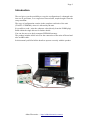
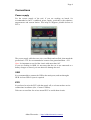
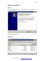
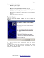
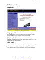
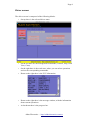
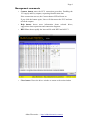
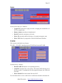
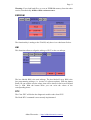
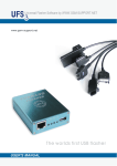
Lince User Manual 1.0
08/05/13
Aldus Electronics - http://alduselectronics.com/en
Page 1
Indice
Lince User Manual 1.0.......................................................................................1
Introduction........................................................................................................2
Kit contents.........................................................................................................3
Connections........................................................................................................4
Power supply.................................................................................................4
USB................................................................................................................4
ECU...............................................................................................................4
Software installation...........................................................................................5
Setup..............................................................................................................5
Directory........................................................................................................5
Device drivers.....................................................................................................6
Software operation..............................................................................................7
Main screen....................................................................................................7
Language select.........................................................................................7
Internet update...........................................................................................7
Driver select..............................................................................................7
Driver screen..................................................................................................8
Management commands...........................................................................9
Immo.......................................................................................................10
FLASH....................................................................................................10
EEPROM.................................................................................................11
KM..........................................................................................................11
DTC.........................................................................................................11
Declaration of conformity ...............................................................................12
Aldus Electronics - http://alduselectronics.com/en
Page 2
Introduction
The tool gives you the possibility to copy the configuration of a damaged unit
into one in good state, or to vergin/reset an used unit, maybe bought from the
scrap merchant.
The copy of configuration consists in the complete read/write of the unit
(FLASH + EEPROM), when it is allowed by the unit.
It's possible to read / write the odometer value directly from the EOBD plug!
Read within the single drivers for further details.
You can also access to body computer EEPROM memory.
The product includes all the wires for the connection of the units off-board and
also an OBD cable.
In this manual you'll find all the details to operate correctly with the product.
Aldus Electronics - http://alduselectronics.com/en
Page 3
Kit contents
The product include this components, that will be described below.
•
The communication interface, composed of an aluminum
case with USB, Jack and DB-25 connectors. Also there are
3 LED for activity information.
•
A Jack red/black cable for power supply.
•
An USB cable for PC connection.
•
An EOBD cable
•
An universal cable
•
A cable for Magneti Marelli 16F
•
A cable for Magneti Marelli 59F
•
A cable for Bosch M155
•
An USB key drive for the software and manual.
Aldus Electronics - http://alduselectronics.com/en
Page 4
Connections
Power supply
For the correct supply of the tool, if you are working on bench, it's
recommended to have a stabilized power supply, preferably with voltmeter,
amperometer and current limiter. This helps to diagnose possible defects in
ECUs.
The power supply cable has two wires, one Black and one Red, that match the
ground and +12V. It's recommended to connect first ground and then +12V.
Note: it's important to not feed the circuit with more than 14V
If you are working in OBD, it's necessary that the car is not connected to a
battery charger or started, you can otherwise damage the tool.
USB
It's recommended to connect the USB to the main ports, and not through a
HUB. At least USB 2.0 port is required.
ECU
It's preferred to wire the ECU with the supply off, or at least not have active
connections in software (See “Connect” button).
Take care to not allow free wires around ECU to avoid short circuits.
Aldus Electronics - http://alduselectronics.com/en
Page 5
Software installation
Setup
Insert the USB key and start the program XXXX.exe where XXXX is the
product serial number.
Follow the installation steps.
Directory
It will be created a folder under c: named Lince (c:\lince).
Aldus Electronics - http://alduselectronics.com/en
Page 6
Inside you'll find the following files
•
lince.exe The lince software
•
uninst.exe To uninstall lince
•
files/ Here you'll eventually find original files for ECU's
•
backup/ under this directory lince saves automatically backup files of
ECU's. If you loose some file you can look here.
•
drivers/ Driver for hardware (If windows ask for drivers, indicate this
directory)
•
pdf/ Possible documents and manuals
Device drivers
When you connect the hardware, windows will notice you about new
hardware.
If it does not find the driver automatically, specify the directory
c:\lince\drivers
The drivers work correctly with Windows 98 SE, Windows ME, Windows
2000, Windows XP 32bit, Windows Vista 32bit,Windows Vista 64bit,
Windows 7 32bit, Windows 7 64bit.
Aldus Electronics - http://alduselectronics.com/en
Page 7
Software operation
Main screen
Language select
Down on the left there's a drop-down menu where you can choose software
language. To apply the new setting you need to restart software.
Internet update
Behind the language selector there is the Internet update button. Click on this
button to check for software updates.
Driver select
On the left side there is a List with supported drivers. Scroll the list to choose
the desired one. Then on the right side you'll see some information about the
driver, such as description, functionality and an image of ECU.
Once you selected the driver, you can continue clicking the red button Open.
Aldus Electronics - http://alduselectronics.com/en
Page 8
Driver screen
The driver screen is composed of the following blocks:
•
On top there is the selected driver name.
•
On the left there are the management commands (Connect, Help, HEX
View, Close)
•
On the right there is the work zone, where you can select operations
and see the corresponding commands.
•
Down on the right there is the ECU information
•
Down on the right there is the message window, with the information
about current operations.
•
At last down there is the progress bar.
Aldus Electronics - http://alduselectronics.com/en
Page 9
Management commands
•
Connect button starts the ECU connection procedure. Enabling the
12V supply and Key outputs, requesting identification data.
If the connection success, the Connect button LED will turn on.
If you click the button again, Lince will disconnect the ECU and turn
off all the outputs.
•
Help button shows more information about selected driver,
suggestions about operations and connection diagrams.
•
HEX View shows rapidly the last read file with HEX and ASCCI
•
Close button Closes the driver window to return to the main window
Aldus Electronics - http://alduselectronics.com/en
Page 10
Immo
In this section there are 5 buttons:
•
Vergin ECU starts the vergin procedure, bringing the immobilizer of
ECU to original state.
•
Remove immo currently not implemented.
•
Read CP reads the emergency card code
•
Write CP currently unlocks the immo for engine emergency start
•
Write VIN allows to program the Vehicle Identification Number
FLASH
This section is divided in two frames.
FLASH 1 e FLASH 2 matching internal FLASH and external FLASH.
Each block has 3 buttons.
•
Read FLASH X Reads the corresponding memory
•
Load File Load the file to be written. The button LED will turn on if
the file is valid. To unload the file click again the button, the LED will
turn OFF
•
Write FLASH Write the loaded file to the ECU
For each frame there is also a check-box to enable the automatic checksum fix.
Aldus Electronics - http://alduselectronics.com/en
Page 11
Warning: If you load both files, or even an EEPROM memory from the other
section, automatically all files will be written at once.
EEPROM
The functionality is analog to the FLASH, only there is no checksum fix box.
KM
This functions allows to align the mileage of ECU to the car mileage.
The box labeled KM is the total mileage, The box labeled Last p. KM is the
last programming mileage (i.e. At time of software update). With the button
Read you can read the current values, that will be shown in the boxes KM and
Last p. KM. With the button Write you can write the values of the
corresponding boxes.
DTC
The Clear DTC will delete the diagnostic trouble codes from ECU.
The Read DTC command is not currently implemented.
Aldus Electronics - http://alduselectronics.com/en
Page 12
Declaration of conformity
According to EN 45014
Under our own responsibility, we declare that the product:
LINCE
as to which this declaration refers conforms to the following
regulations:
a) EN 55022
b) EN 55024
as prescribed by the directive 89/336/EEC
Place of issue: ITALY
Date of issue: 20 February 2012
In good faith,
__________________
Aldo Nicolas Bruno
Aldus Electronics - http://alduselectronics.com/en