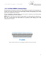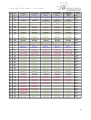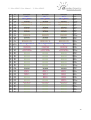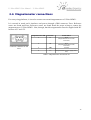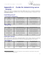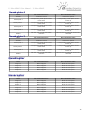
1
V 0.6
U- Pilot OEM51 User Manual -
Table of Contents
1 General System Introduction.............................................................................................3
1.1 Concept of system operation......................................................................................4
2 Controllable Air vehicles.....................................................................................................5
2.1 Fixed wing...................................................................................................................5
2.1.1 Conventional configuration fixed wing.................................................................5
2.1.2 Flying wing configuration.....................................................................................5
2.2 Rotary wing.................................................................................................................5
2.2.1 Helicopter (Swash-plate 4)..................................................................................5
2.2.2 Helicopter (Swash-plate 3)..................................................................................5
2.2.3 Helicopter (Direct Drive)......................................................................................6
2.2.4 Quadcopter..........................................................................................................6
2.2.5 Hexacopter..........................................................................................................6
2.2.6 Octocopter...........................................................................................................7
3 U-Pilot OEM51...................................................................................................................8
3.1 Power supply..............................................................................................................8
3.2 Monitoring Engine Data..............................................................................................9
3.3 Microprocessors structure..........................................................................................9
3.4 Sensors.......................................................................................................................9
3.5 U-Pilot OEM51 Connections.....................................................................................11
3.6 Magnetometer connections......................................................................................14
Appendix A Guide for determining servo reverse................................................................15
Fixed Wing servos...........................................................................................................15
Helicopter Servos............................................................................................................15
Direct Servos...............................................................................................................15
Swash-plate 4..............................................................................................................16
Swash-plate 3..............................................................................................................16
Quadcopter......................................................................................................................16
Hexacopter.......................................................................................................................16
Octocopter.......................................................................................................................17
Appendix B Changelog........................................................................................................18
2
U- Pilot OEM51 User Manual - General System Introduction
1 General System Introduction
Airelectronics has developed a complete solution for both rotary and fixed wing UAVs. The
system is composed of:
•
U-Pilot, U-Pilot OneBoard or U-Pilot OEM51
•
U-Ground
•
U-See
U-Pilot takes care of the vehicle from Take-off to Landing. It is completely adaptable to any
aircraft including fixed wing, hexacopters, quadcopters and helicopters.
U-Pilot is completely capable of following a flight plan with up to 200 points (real time
editable). Once the flight plan is loaded on the U-Pilot it is independent of operator
instructions. In case of a failure in the communications, U-Pilot starts a Landing maneuver
which would safely land the UAV on the Runway Point.
Thanks to its versatility U-Pilot can control any device on board the UAV such as cameras,
parachutes and others. These devices can be real time controlled by a Computer Operator
or by U-Pilot automatically.
U-Pilot OEM51 has, working in parallel:
•
30 PWM (Pulse-Width Modulation) outputs or even more if necessary,
•
3 ADC inputs (Analogical Digital Converter) to monitor the voltages of three
batteries on the UAV
•
4 serial ports RS232 to communicate with payloads, external magnetometers, etc.
•
A radio with up to 100 km1
•
GPS, dynamic and static pressure sensors, a magnetometer, gyroscopes and
accelerometers.
U-Pilot OEM51 is built using a two parallel microprocessor approach:
•
One processor takes care of the state estimator and controls the UAV using
hardware acceleration to calculate high speed algorithms.
•
Another processor takes care of the mission at high level and the communications
with the U-Ground and Payloads management.
•
The processors do not waste any time doing low level tasks.
Due to the fact that those two processors are working in parallel and there is dedicated
electronics taking care of all the serial ports, sensors, inputs and outputs the system is
capable of recalculating its position, orientation and closing control loops at the speed of
1000 Hz. This high speed gives the the UAV huge navigation accuracy and control.
On the ground segment, we have both U-Ground and U-See.
U-Ground is a control station with the other end of the radio link communicating the U-Pilot
with the U-See software.
U-See software is a user friendly program that runs in any personal computer running
Windows or Linux.
1 Range may vary with the frequency band used. Default is 900 MHz but legal limitations in some countries may
change this.
3
U- Pilot OEM51 User Manual - General System Introduction
Through U-See, the UAV operator can inspect the current state of the mission and
command it in real-time.
All the U-Pilot configuration is done by Airelectronics staff so the End User does not have to
waste any time setting the internal parameters of the system.
1.1 Concept of system operation
The system is made up of an U-Pilot installed on an aircraft connected to the U-Ground
through a radio link. (See figure 1 attached below)
The U-Ground has its own radio link to communicate with the U-Pilot. It also has an RS-232
output to relay the data to a PC running U-See to allow control from the End User.
A Futaba Joystick allows manual override and control.
Figure 1: System concept
The mission team usually is formed by two persons:
•
The External Pilot who will have the Futaba Joystick on its hands, in case a manual
control of the UAV is desired (specially during the development and adjustment
phase).
•
The U-See operator that will command the mission using the PC.
4
U- Pilot OEM51 User Manual - Controllable Air vehicles
2 Controllable Air vehicles
U-Pilot is able to control Fixed Wing and Rotary Wing vehicles. Each unit is configured for a
specific type of vehicle.
2.1 Fixed wing
Fixed wing can take-off automatically on a runway, hand launched or catapulted.
The automatic landing can be done using a parachute or on a runway.
At the time of performing the connections of the servos to the U-Pilot refer to U-Pilot
OEM51 connections.
2.1.1 Conventional configuration fixed wing
Conventional configuration planes are supported with redundant elevator and separated
channels for left and right ailerons and flaps.
Other configurations/equipment are supported (spoilers support, parachute deployment for
landing, etc.) upon request. Please contact us for this kind of configuration.
2.1.2 Flying wing configuration
Tailless flying wing is supported and aileron control is separated in two channels per wing
to improve reliability and enable usage of butterfly air-brake deployment.
2.2 Rotary wing
Rotary wing configuration group different vehicles. U-Pilot can be configured for the
following type (extra configuration will be added in the future)
2.2.1 Helicopter (Swash-plate 4)
The helicopter has a swash-plate driven by four servos. These
servos should be connected to U-Pilot following the attached
schematic.
Servo 1 is forward mounted.
Servo 2 is right mounted.
Servo 3 is back mounted.
Servo 4 is left mounted.
The U-Pilot OEM51 motors connection is detailed in U-Pilot
OEM51 connections.
Figure 2: Helicopter servo
distribution
2.2.2 Helicopter (Swash-plate 3)
The helicopter configured as swash-plate 3 has a swash-plate
driven by three servos. These servos should be connected to UPilot following the attached schematic.
Servo 1 is forward-right mounted.
Servo 2 is back mounted.
5
Figure 3: Helicopter
(Swash-plate 3) servo
distribution
U- Pilot OEM51 User Manual - Controllable Air vehicles
Servo 3 is forward-left mounted.
The U-Pilot OEM51 motors connection is detailed in U-Pilot OEM51 connections.
2.2.3 Helicopter (Direct Drive)
The helicopter has a swash-plate driven by three servos. These
servos should be connected to U-Pilot following the attached
schematic.
Servo 1 drives cyclic pitch
Servo 2 drives cyclic roll
Servo 3 drives collective
Note that as every movement of the swash-plate is assigned
exclusively to a servo, you don't need to respect the right/left
or forward/back indications of the diagram, as you can always
check “inverse” in the servos adjustment step.
Figure 4: Helicopter (direct
swash plate) servo
distribution
The U-Pilot OEM51 motors connection is detailed in U-Pilot
OEM51 connections.
2.2.4 Quadcopter
The quadcopter motors distribution and the rotation direction is
represented in the attached schematic.
The quadcopter motors distribution and the rotation direction is
represented in the attached schematic.
Notice that motors number 1-3 must turn clockwise and motors
number 2-4 must turn anticlockwise.
The U-Pilot OEM51 motors connection is detailed in U-Pilot
OEM51 connections.
Figure 5: Quadcopter
motors distribution
2.2.5 Hexacopter
The hexacopter motors distribution and the rotation direction is
represented in the attached schematic.
Notice that motors number 1-3-5 must turn clockwise and motors
number 2-4-6 must turn anticlockwise.
The U-Pilot OEM51 motors connection is detailed in U-Pilot
OEM51 connections.
Figure 6: Hexacopter
motors distribution
6
U- Pilot OEM51 User Manual - Controllable Air vehicles
2.2.6 Octocopter
The octocopter motors distribution and the rotation direction is
represented in the attached schematic.
Notice that motors number 1-3-5-7 must turn clockwise and motors
number 2-4-6-8 must turn anticlockwise.
The U-Pilot OEM51 motors connection is detailed in U-Pilot OEM51
connections.
Figure 7: Octopter motors
distribution
7
U- Pilot OEM51 User Manual - U-Pilot OEM51
3 U-Pilot OEM51
The U-Pilot OEM51 is powered in the range from 6.0V
to 24V, view Power Supply. This allows the
connection of U-Pilot OEM51 directly to a 2S LiPo
battery without adding possible points of failure in
the system.
If the system uses 6V servos, U-Pilot OEM51 can be
connected directly to the servo power and save
weight.
The power installation can be done in several
different ways described in Power Supply section.
U-Pilot OEM51 has three ADC available channels to
monitor system voltages, and it is possible to
connect a Hall-Effect amperometer sensor to control
the discharge of battery in electric UAVs.
There are 30 PWM outputs signals at 50, 200, 300,
333 or 540Hz frequencies and 1500 or 760 us pulses.
Figure 8: U-Pilot OEM51 I/O Schematic
PWM at 50Hz is the most common way to control
servos and it will be accepted by almost any servo in
the market. This signal pulses every 20 ms
(milliseconds), and depending on the length of these
pulses the servo will move to different positions.
Digital servos (300Hz) can accept much faster control input and are the recommended
choice when control rotary wing aircraft.
Upon request, all the PWM lines can be reconfigured to output or input any other digital
signal.
There are 4 serial ports also available for additional devices use, such as cameras or
magnetometers.
Serial ports are automatically adapted to the baud rate of the devices connected to it. The
voltage levels for the serial ports are the standard +12V/-12V.
Connector pin configuration is detailed on U-Pilot OEM51 Connections section.
3.1 Power supply
U-Pilot OEM51 is powered in the range from 6.0V to 24V. Main power voltage is directly
connected to the ADC channel number 4, thus allowing monitor of AP battery and check
for voltage supply stability. This level is displayed as an internal battery 4 on the U-See
state window (Consult U-See manual for details)
CAUTION: Power the Autopilot at a voltage OUT of range can cause IRREVERSIBLE
DAMAGE to the system. Please read carefully this manual and do not hesitate to contact us
(www.airelectronics.es) if needed.
Typical power consumption about 6 Watt, but the power system should be prepared to
withstand 9 Watts peaks. This consumption will mean an intensity consumption of 1 Amp.
at 6V or 0.5 Amp. at 12 V.
8
U- Pilot OEM51 User Manual - U-Pilot OEM51
3.2 Monitoring Engine Data
A better estimation of the battery status on electric vehicles is available by adding an
amperometer connected to the ADC3 on the U-Pilot OEM51. The amperometer is a linear
hall effect sensor supplied by Airelectronics.
This configuration allows the user to improve the efficiency of the flight. For further
information of its usage check the Engine Data section of the U-See manual.
3.3 Microprocessors structure
The Autopilot has two microprocessors (CPUs).
–
CPU Mission control. This CPU manages Communications to and from ground
segment, the management of payloads and, in general, operations that are not
flight related.
–
CPU Flight control. This CPU produces the surfaces commands and control the
attitude of the aircraft. This processor access all its sensors in a non-blocking way
and it is always evaluating current position, attitude and control.
Figure 9: General system architecture.
3.4 Sensors
There are several sensors inside U-Pilot OEM51 and all of them have their own electronics
design inside the system taking care of them, this gives the highest reliability and
performance to the system. The sensors are:
–
Accelerometers
–
Gyroscopes
–
GPS with Satellite Based Augmentation System
–
Several Static Pressure Sensor to improve accuracy in different altitude ranges.
–
Several Dynamic Pressure Sensors for higher accuracy during take-off and landing
operations. Different sensors account for different speed segments of the mission.
These sensors are only used in Fixed Wing UAVs
Besides these internal sensors, for rotary wing we use an external magnetometer. It is
connected to the system through RS-232 port and interfaces with dedicated electronics in
9
U- Pilot OEM51 User Manual - U-Pilot OEM51
U-Pilot OEM51. Due to the fact that this sensor is external it can be placed far from any
electromagnetic noise inside the UAV. However, it must be connected to the proper main
connector on U-Pilot OEM51. (See section 3.5)
If, for some reason, a external dynamic pressure sensor is needed, the system has the
provisions to make use of an Airelectronics external I2C sensor that can be mounted
separately from U-Pilot OEM51. This sensor is only provided upon request.
The sensor suite is very flexible and can be modified to reflect a customer requirement on
the system.
10
U- Pilot OEM51 User Manual - U-Pilot OEM51
3.5 U-Pilot OEM51 Connections
The aerial part of connector used for the U-Pilot OEM51 is provided in the Installation Kit.
Cables in the aerial connector are colour coded. The following table describes the function
of every pin in the main connector in U-Pilot OEM51 and the corresponding colour coded
cable in the supplied aerial connector.
The pin configuration used depending on the UAV vehicle is detailed in the following table
and the corresponding connector diagram.
NOTE: Please, take into account than in these tables, Tx and Rx suffix are referred to UPilot. This is: a line marked as “Magnetometer Rx” is the pin dedicated to receive data
from the magnetometer, and thus, must be connected to the sending pin in the
magnetometer connector.
Figure 10: Main connector on U-Pilot OEM51 One Board as seen from the front.
11
U- Pilot OEM51 User Manual - U-Pilot OEM51
PIN
I/O
FixedWing
Flying Wing
1
2
3
4
In
In
DC in
GND
ADC 2
ADC 1 / Battery
VIN
Ground
ADC 2
ADC 1 / Battery
VIN
Ground
5
In
Engine ECU Rx
Engine ECU Rx
6
7
8
9
10
11
Out
Out
GND
In
Out
GND
12
Out
13
14
15
16
17
18
In
Out
GND
NC
In
Out
19
In
20
21
22
23
24
25
26
27
28
29
30
31
32
33
34
DC in
In
In
Out
NC
NC
NC
NC
NC
NC
NC
NC
NC
NC
NC
35
Out
36
37
38
39
40
41
42
43
44
45
46
47
48
49
50
51
GND
Out
Out
Out
Out
Out
Out
Out
Out
Out
NC
NC
NC
NC
NC
NC
Engine ECU Tx
Engine ECU Tx
Engine Kill
Engine Kill
Ground
Ground
DGPS Rx
DGPS Rx
DGPS Tx
DGPS Tx
Ground
Ground
1-Wire
1-Wire
Temperature
Temperature
Sensor
Sensor
Payload Rx
Payload Rx
Payload Tx
Payload Tx
Ground
Ground
Reserved
Reserved
RS232 Port 1 Rx RS232 Port 1 Rx
RS232 Port 1 Tx RS232 Port 1 Tx
ADC 3 /
ADC 3 /
Amperimeter
Amperimeter
VIN
VIN
Camera Pan
Camera Pan
Camera Tilt
Camera Tilt
Camera Roll
Camera Roll
Camera Shutter Camera Shutter
Reserved
Reserved
Reserved
Reserved
Reserved
Reserved
Reserved
Reserved
Reserved
Reserved
Reserved
Reserved
Reserved
Reserved
Reserved
Reserved
Reserved
Reserved
Reserved
Reserved
DGPS-TTL
DGPS-TTL
Correction
Correction
Ground
Ground
Throttle
Throttle
Right Aileron
Out Right aileron
Elevator
In Left aileron
Rudder
Rudder
Left Aileron
Out Left aileron
Left Flap
Left Flap
Elevator 2
In Right Aileron
Right Flap
Right Flap
Nose Wheel
Nose Wheel
2nd Aileron Right
Reserved
2nd Aileron Left
Reserved
2nd Flap Right
Reserved
2nd Flap Left
Reserved
Reserved
Reserved
Reserved
Reserved
Helicopter
Swash-plate 4
Helicopter
Swash-plate 3
ADC 2
ADC 1 / Battery
VIN
Ground
Magnetometer
Rx
Magnetometer Tx
Engine Kill
Ground
DGPS Rx
DGPS Tx
Ground
1-Wire
Temperature
Sensor
Payload Rx
Payload Tx
Ground
Reserved
RS232 Port 1 Rx
RS232 Port 1 Tx
ADC 3 /
Amperimeter
VIN
Camera Pan
Camera Tilt
Camera Roll
Camera Shutter
Reserved
Reserved
Reserved
Reserved
Reserved
Reserved
Reserved
Reserved
Reserved
Reserved
DGPS-TTL
Correction
Ground
Throttle
Swash-plate 1
Swash-plate 2
Tail Servo
Swash-plate 3
Swash-plate 4
Reserved
Reserved
Reserved
Reserved
Reserved
Reserved
Reserved
Reserved
Reserved
ADC 2
ADC 1 / Battery
VIN
Ground
Magnetometer
Rx
Magnetometer Tx
Engine Kill
Ground
DGPS Rx
DGPS Tx
Ground
1-Wire
Temperature
Sensor
Payload Rx
Payload Tx
Ground
Reserved
RS232 Port 1 Rx
RS232 Port 1 Tx
ADC 3 /
Amperimeter
VIN
Camera Pan
Camera Tilt
Camera Roll
Camera Shutter
Reserved
Reserved
Reserved
Reserved
Reserved
Reserved
Reserved
Reserved
Reserved
Reserved
DGPS-TTL
Correction
Ground
Throttle
Swash-plate 1
Swash-plate 2
Tail Servo
Swash-plate 3
Reserved
Reserved
Reserved
Reserved
Reserved
Reserved
Reserved
Reserved
Reserved
Reserved
Helicopter
Direct Swashplate
Cable
Colour
ADC 2
Black
ADC 1 / Battery Brown
VIN
Red
Ground
Orange
Magnetometer
Yellow
Rx
Magnetometer Tx Green
Engine Kill
Blue
Ground
Purple
DGPS Rx
Grey
DGPS Tx
White
Ground
Black
1-Wire
Temperature Brown
Sensor
Payload Rx
Red
Payload Tx
Orange
Ground
Yellow
Reserved
Green
RS232 Port 1 Rx Blue
RS232 Port 1 Tx Purple
ADC 3 /
Grey
Amperimeter
VIN
White
Camera Pan
Black
Camera Tilt
Brown
Camera Roll
Red
Camera Shutter Orange
Reserved
Yellow
Reserved
Green
Reserved
Blue
Reserved
Purple
Reserved
Grey
Reserved
White
Reserved
Black
Reserved
Brown
Reserved
Red
Reserved
Orange
DGPS-TTL
Yellow
Correction
Ground
Green
Throttle
Blue
Cyclic Pitch
Purple
Cyclic Roll
Grey
Tail Servo
White
Collective
Black
Reserved
Brown
Reserved
Red
Reserved
Orange
Reserved
Yellow
Reserved
Green
Reserved
Blue
Reserved
Purple
Reserved
Grey
Reserved
White
Reserved
Black
12
U- Pilot OEM51 User Manual - U-Pilot OEM51
PIN
I/O
Quadcopter
Hexacopter
Octocopter
1
2
3
4
5
6
7
8
9
10
11
12
13
14
15
16
17
18
19
20
21
22
23
24
25
26
27
28
29
30
31
32
33
34
35
36
37
38
39
40
41
42
43
44
45
46
47
48
49
50
51
In
In
DC in
GND
In
Out
Out
GND
In
Out
GND
Out
In
Out
GND
NC
In
Out
In
DC in
In
In
Out
NC
NC
NC
NC
NC
NC
NC
NC
NC
NC
NC
In
GND
Out
Out
Out
Out
Out
Out
Out
Out
Out
NC
NC
NC
NC
NC
NC
AADC 2
ADC 1 / Battery
VIN
Ground
Magnetometer Rx
Magnetometer Tx
Engine Kill
Ground
DGPS Rx
DGPS Tx
Ground
1-Wire Temperature Sensor
Payload Rx
Payload Tx
Ground
Reserved
RS232 Port 1 Rx
RS232 Port 1 Tx
ADC 3 / Amperimeter In
VIN
Camera Pan
Camera Tilt
Camera Roll
Camera Shutter
Reserved
Reserved
Reserved
Reserved
Reserved
Reserved
Reserved
Reserved
Reserved
Reserved
Reserved
Ground
Motor 1
Motor 2
Motor 3
Motor 4
Reserved
Reserved
Reserved
Reserved
Nose Wheel
Reserved
Reserved
Reserved
Reserved
Reserved
Reserved
ADC 2
ADC 1 / Battery
VIN
Ground
Magnetometer Rx
Magnetometer Tx
Engine Kill
Ground
DGPS Rx
DGPS Tx
Ground
1-Wire Temperature Sensor
Payload Rx
Payload Tx
Ground
Reserved
RS232 Port 1 Rx
RS232 Port 1 Tx
ADC 3 / Amperimeter In
VIN
Camera Pan
Camera Tilt
Camera Roll
Camera Shutter
Reserved
Reserved
Reserved
Reserved
Reserved
Reserved
Reserved
Reserved
Reserved
Reserved
Reserved
Ground
Motor 1
Motor 2
Motor 3
Motor 4
Motor 5
Motor 6
Reserved
Reserved
Nose Wheel
Reserved
Reserved
Reserved
Reserved
Reserved
Reserved
ADC 2
ADC 1 / Battery
VIN
Ground
Magnetometer Rx
Magnetometer Tx
Engine Kill
Ground
DGPS Rx
DGPS Tx
Ground
1-Wire Temperature Sensor
Payload Rx
Payload Tx
Ground
Reserved
RS232 Port 1 Rx
RS232 Port 1 Tx
ADC 3 / Amperimeter In
VIN
Camera Pan
Camera Tilt
Camera Roll
Camera Shutter
Reserved
Reserved
Reserved
Reserved
Reserved
Reserved
Reserved
Reserved
Reserved
Reserved
Reserved
Ground
Motor 1
Motor 2
Motor 3
Motor 4
Motor 5
Motor 6
Motor 7
Motor 8
Nose Wheel
Reserved
Reserved
Reserved
Reserved
Reserved
Reserved
Cable Colour
Black
Brown
Red
Orange
Yellow
Green
Blue
Purple
Grey
White
Black
Brown
Red
Orange
Yellow
Green
Blue
Purple
Grey
White
Black
Brown
Red
Orange
Yellow
Green
Blue
Purple
Grey
White
Black
Brown
Red
Orange
Yellow
Green
Blue
Purple
Grey
White
Black
Brown
Red
Orange
Yellow
Green
Blue
Purple
Grey
White
Black
13
U- Pilot OEM51 User Manual - U-Pilot OEM51
3.6 Magnetometer connections
For rotary wing platforms, it is need to connect an external magnetometer to U-Pilot OEM51.
It is encased in metal and it interfaces and powers through a DB9 connector. Error: Reference
source not found and Error: Reference source not found detail the proper wiring to connect the
magnetometer to U-Pilot OEM51. Note, through, that this magnetometer must be supplied with DC
between 6.5V and 15V.
Figure 11: Magnetometer
connector viewed from the
front.
Magnetometer PIN
Function
Connected to
2
TX
Pin 6
(Magnetometer TX in main
connector)
3
RD
Pin 5
(Magnetometer RX in main
connector)
5
GND
Ground
Vcc
Magnetometer power supply.(6.5V15V)
9
Table 1: Magnetometer connection list
14
U- Pilot OEM51 User Manual - U-Pilot OEM51
Appendix A
reverse
Guide for determining servo
When a new vehicle is configured with U-Pilot OEM51 and U-See it is needed to determine
if “Reverse” check-box should be active. Follow the following tables to determine if your
servos need reversal.
Fixed Wing servos2
Conventional configuration
Servo
Min commanded action
Max Commanded action
Throttle
Carburator closed
Carburator opened
Aileron Right
Right aileron trailing edge up
Right aileron trailing edge down
Elevator
Elevator trailing edge up
Elevator trailing edge down
Rudder
Rudder trailing edge right
Rudder trailing edge left
Aileron Left
Left aileron trailing edge down
Left aileron trailing edge up
Wheel
Steer right
Steer left
Servo
Min commanded action
Max Commanded action
Throttle
Carburator closed / motor stopped
Carburator opened / motor at max speed
Outward Left aileron
Left aileron trailing edge down
Left aileron trailing edge up
Inward Left Aileron
Left aileron trailing edge up
Left aileron trailing edge up
Rudder
Rudder trailing edge right
Rudder trailing edge left
Outward Right Aileron
Right aileron trailing edge up
Right aileron trailing edge down
Inward Right Aileron
Right aileron trailing edge up
Right aileron trailing edge down
Wheel
Steer right
Steer left
Flying Wing
Helicopter Servos
When referring the swash-plate, left/right/front/back will be always referred as watching
the swash-plate from above and in the direction of forward movement of the vehicle
Direct Servos
Servo
Min commanded action
Max Commanded action
Throttle
Carburator closed
Carburator opened
Collective
Full Swash-plate down
Full Swash-plate up
Swash-plate tilts right
Swash-plate tilts left
Cyclic Pitch
Swash-plate tilts backwards
Swash-plate tilts forward
Rudder
Tail rotor acts to make tail rotates
clockwise
Tail rotor acts to make tail rotates anticlockwise
Cyclic Roll
2 This section assumes conventional aircraft configuration. Canard configurations require different settings, please
contact Airelectronics if that's your case
15
U- Pilot OEM51 User Manual - U-Pilot OEM51
Swash-plate 4
Servo
Min commanded action
Max Commanded action
Throttle
Carburator closed
Carburator opened
Swash-plate 1
Corresponding swash-plate section
moves down
Corresponding swash-plate section
moves up
Corresponding swash-plate section
moves down
Corresponding swash-plate section
moves up
Swash-plate 3
Corresponding swash-plate section
moves down
Corresponding swash-plate section
moves up
Swash-plate 4
Corresponding swash-plate section
moves down
Corresponding swash-plate section
moves up
Rudder
Tail rotor acts to make tail rotates
clockwise
Tail rotor acts to make tail rotates anticlockwise
Min commanded action
Max Commanded action
Swash-plate 2
Swash-plate 3
Servo
Throttle
Carburator closed
Carburator opened
Swash-plate 1
Corresponding swash-plate section
moves down
Corresponding swash-plate section
moves up
Corresponding swash-plate section
moves down
Corresponding swash-plate section
moves up
Swash-plate 3
Corresponding swash-plate section
moves down
Corresponding swash plate section
moves up
Rudder
Tail rotor acts to make tail rotates
clockwise
Tail rotor acts to make tail rotates anticlockwise
Servo
Min commanded action
Max Commanded action
Engine 1
Motor stopped
Motor at max speed
Engine 2
Motor stopped
Motor at max speed
Motor stopped
Motor at max speed
Motor stopped
Motor at max speed
Servo
Min commanded action
Max Commanded action
Engine 1
Motor stopped
Motor at max speed
Engine 2
Motor stopped
Motor at max speed
Motor stopped
Motor at max speed
Engine 4
Motor stopped
Motor at max speed
Engine 5
Motor stopped
Motor at max speed
Engine 6
Motor stopped
Motor at max speed
Swash-plate 2
Quadcopter
Engine 3
Engine 4
Hexacopter
Engine 3
16
U- Pilot OEM51 User Manual - U-Pilot OEM51
Octocopter
Servo
Min commanded action
Max Commanded action
Engine 1
Motor stopped
Motor at max speed
Engine 2
Motor stopped
Motor at max speed
Engine 6
Motor stopped
Motor at max speed
Engine 4
Motor stopped
Motor at max speed
Engine 5
Motor stopped
Motor at max speed
Engine 6
Motor stopped
Motor at max speed
Engine 7
Motor stopped
Motor at max speed
Engine 8
Motor stopped
Motor at max speed
17
U- Pilot OEM51 User Manual - U-Pilot OEM51
Appendix B Changelog
This annex describes changes introduced to this document.
Date
2014/10/27
Changes
•
•
Version of document started 0.5
Created Document
If you need a previous
[email protected]
version
of
documentation,
please,
contact
us
at
18