1
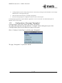
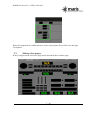
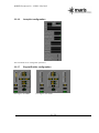
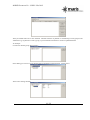
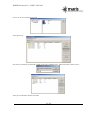
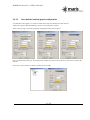
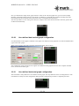
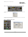
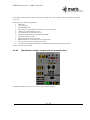
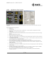
MARIS Document No.: COIM 201410-B Maritime Information Systems AS CONNING DISPLAY INSTALLATION AND SET UP QUICK GUIDE 2014 Maritime Information Systems AS. All rights reserved. The copyright of this document is the property of Maritime Information Systems AS. The document is supplied on the express terms that it is to be treated as confidential. No part of this document may be reproduced or transmitted in any form or by any means, electronic or mechanical for any purpose, without the express written permission of Maritime Information Systems AS. The information in this document is subject to change without notice and is provided "AS IS". 1 / 29 MARIS Document No.: COIM 201410-B DOCUMENT STATUS Release Date Paragraph(s) Prepared by Description of Change A 10/09/2014 All ET First draft B 28/09/2014 All PK All reviewed 2 / 29 MARIS Document No.: COIM 201410-B DOCUMENT STATUS ...................................................................................................................................................... 2 1. General................................................................................................................................................................ 4 2. Conning Display ................................................................................................................................................. 4 3. 2.1 Installation ...................................................................................................................................................... 4 2.2 Configuration of the page “Navigation” ........................................................................................................ 5 2.3 Adding other pages ......................................................................................................................................... 7 Components set up ............................................................................................................................................. 8 3.1 List of components .......................................................................................................................................... 8 3.2 Set up ............................................................................................................................................................... 9 3.2.1 Position instrument configuration .......................................................................................................... 9 3.2.2 GPS Console configuration ................................................................................................................... 9 3.2.3 Time instrument configuration .............................................................................................................. 9 3.2.4 Gyro instrument configuration ............................................................................................................ 10 3.2.5 Gyro Recorder configuration ............................................................................................................... 10 3.2.6 Gyro/Log instrument configuration ..................................................................................................... 10 3.2.7 Rate of turn instrument configuration .................................................................................................. 11 3.2.8 Rudder (wide scale or angle scale) ...................................................................................................... 11 3.2.9 Engine indicator configuration ............................................................................................................ 12 3.2.10 Telegraph configuration .................................................................................................................. 12 3.2.11 Fuel meter configuration ................................................................................................................. 13 3.2.12 Vessel movement console configuration ........................................................................................ 14 3.2.13 Wind instruments configuration ..................................................................................................... 14 3.2.14 Depth recorder configuration .......................................................................................................... 15 3.2.15 Autopilot configuration ................................................................................................................... 16 3.2.16 Engine/Rudder configuration .......................................................................................................... 16 3.2.17 PLC channels .................................................................................................................................. 17 3.2.18 User-defined vertical graph configuration ...................................................................................... 21 3.2.19 User-defined dual vertical graph configuration .............................................................................. 22 3.2.20 User-defined horizontal graph configuration. ................................................................................. 22 3.2.21 Single float indicator configuration ................................................................................................ 23 3.2.22 Predefined layouts........................................................................................................................... 23 3.2.23 Stolt Nielsen full console ................................................................................................................ 23 3.2.24 Stolt Nielsen full console with one engine only .............................................................................. 24 3.2.25 Reduced Stolt Nielsen console (takes just top half of the screen) ................................................... 25 3.2.26 Stolt Nielsen overlay console .......................................................................................................... 25 3.2.27 Stolt Nielsen overlay console without propeller pitch .................................................................... 26 3.2.28 Stolt Nielsen "final" console ........................................................................................................... 27 3.2.29 Stolt Nielsen "final" console with track steering ............................................................................ 29 3.2.30 Pinnacle Spirit console .................................................................................................................... 29 3 / 29 MARIS Document No.: COIM 201410-B 1. GENERAL MARIS Conning display is a software application running on one of the ECDIS900 workstation. The Conning application is displayed either on the main ECDIS screen or, when the ECDIS900 is equipped with a second screen, on the second screen. The dual screen installation is recommended when Conning Display is running on ECDIS900 Monitoring station Installation. 2. 2.1 CONNING DISPLAY Installation The Conning Display SW is delivered with an installer called: ConningDisplaySetup.exe”. Double click on the exe file and follow instructions. By default the application is installed in the folder: “Program File/MARIS/Conning Display” 4 / 29 MARIS Document No.: COIM 201410-B Conning Display Layout is empty and you have to create one by Ticking ON the CheckBox “Create simple default layout” in the appropriate page. Enter the name for the layout. For example “Navigation”. Run the Conning Display in configuration mode in order to edit the layout. Conning Display application requires SMonitor application to work on the LAN. For detailed description of SMonitor refer to user manual. 2.2 Configuration of the page “Navigation” Conning Display starts with a single page called “Navigation”. Top right of the application the pop up menu “Configure” allows editing the layout of the Conning Display page but also adding new page to the layout. Select “Configure Current Page” to edit the page “Navigation” The page “Navigation” is opened for edition 5 / 29 MARIS Document No.: COIM 201410-B It is possible to add component by activating “Insert” and selecting a pre defined component: The new component is added and it is possible to move it by simple click and move 6 / 29 MARIS Document No.: COIM 201410-B When all components are added and move to the selected place Press OK to save the page “Navigation”. 2.3 Adding other pages In the Configure menu select New page and as described above edit the page Configuration with three pages. 7 / 29 MARIS Document No.: COIM 201410-B 3. COMPONENTS SET UP 3.1 List of components Console type Position GPS console Time Gyro Gyro recorder Gyro/Log Rate of turn Rudder (wide scale) Rudder (angle scale) Engine indicator Telegraph Power meter Fuel meter Vessel movement console Wind Depth recorder Autopilot Engine/Rudder PLC channels User-defined vertical graph User-defined dual vertical graph User-defined Which data are shown Lat, Lon, GPS quality indicator, PS mode indicator Lat, Lon, GPS quality indicator, PS mode indicator, UTC, date, TZ, COG, SOG TZ, date, UTC HDG, COG HDG, ROT HDG, STW ROT Rudder sensor angle feedback (one instrument shows the only rudder; you need two instruments to show two rudders if there are two of them) Rudder sensor angle order (if present) and feedback (one instrument shows the only rudder; you need two instruments to show two rudders if there are two of them) Engine shaft or engine RPM, propeller pitch (one instrument shows the only engine; you need two instruments to show two engines if there are two of them) Lever position pitch (one instrument shows the only engine control lever; you need two instruments to show two engines if there are two of them) Torque, thrust, power, RPM, total energy, total revolutions (one instrument shows the only engine; you need two instruments to show two engines if there are two of them) Fuel consumption, temperature and counter (both volumentaric and mass). Transverse and longitudinal SOG and STW (the final data layout depends on speedlog settings) There are several wind instruments. All of them show wind direction and speed. The difference is that following kind of data might be shown: true or relative wind speed measured in knots or m/s There is also switcheable instrument that could be set up dynamically. One of depths (DBK, DBS, DBT) CTS, HTS, turn rate, origin and destination waypoints, destination waypoint range (from origin and from present point), destination waypoint bearing (from origin and from present point), present position, destination position, GPS mode, autopilot status, Loran-C status Shaft or engine RPM, propeller pitch, SOG, COG, longitudinal and transverse speed, rudder sensor angle. Instrument may show data from one or two engines and one or two rudders. Some number of engineer data (as well discrete as analog) such as temperatures, current, voltage etc. These data might be obtained from PLCs, NMEA XDR sentences, MODBUS/TCP devices and so on. Any generic data or analog PLC channel value Any two generic data or analog PLC channel value Any generic data or analog PLC channel value 8 / 29 MARIS Document No.: COIM 201410-B horizontal graph Single float indicator Predefined layouts 3.2 3.2.1 Any generic data See below Set up Position instrument configuration Right click on the console in the layout editor to activate context menu, then select Properties. Configuration dialog will be shown. The only setting is a number of GPS that will be shown by default in case of several position sources. Note that during the normal run you can switch to another position source, just click on white text that shows position source sensor name, then Conning Display will switch to the next position source. This switch works as a loop, i.e. after last position source Conning Display will switch onto first one. 3.2.2 GPS Console configuration The configuration is fully equal to Position instrument. 3.2.3 Time instrument configuration 9 / 29 MARIS Document No.: COIM 201410-B The configuration is fully equal to Position instrument. 3.2.4 Gyro instrument configuration This instrument has no configurable parameters. 3.2.5 Gyro Recorder configuration This instrument has no configurable parameters. 3.2.6 Gyro/Log instrument configuration This instrument has no configurable parameters. 10 / 29 MARIS Document No.: COIM 201410-B 3.2.7 Rate of turn instrument configuration This instrument has no configurable parameters. 3.2.8 Rudder (wide scale or angle scale) Note: one instrument shows the only rudder; you need two instruments to show two rudders if there are two of them. Right click on the console in the layout editor to acitivate context menu, then select Properties. Configuration dialog will be shown. The only setting is a number of rudder sensor that will be used (i.e. number of the physical rudder). One is starboard rudder (or single rudder if the only rudder exists); two is port rudder. Example for two rudders (starboard rudder sensor shows 3 deg stbd, port rudder sensor shows 4 deg stbd) 11 / 29 MARIS Document No.: COIM 201410-B 3.2.9 Engine indicator configuration Note: one instrument shows the only engine; you need two instruments to show two engines if there are two of them. Right click on the console in the layout editor to acitivate context menu, then select Properties. Configuration dialog will be shown. Please specify the following data: number of engine (this depends on Sensor Monitor configuration; numbers are zero-based) maximal absolute RPM value (needs to graduate the scale; it is recommended to put this value slightly bigger than actual max revolutions); please note that if machine has reverse revolutions, this value will be used to both sides, that means, instrument will show for example revolutions from -100 (astern) to 100 (ahead) RPM. RPM multiplier (some sensors present revolutions reduced to 10 or 100) tick Enable reverse if machine has reverse (negative) revolutions for astern movement Example for two engines: 3.2.10 Telegraph configuration 12 / 29 MARIS Document No.: COIM 201410-B Note: one instrument shows the only engine; you need two instruments to show two engines if there are two of them. Right click on the console in the layout editor to activate context menu, then select Properties. Configuration dialog will be shown. Specify RPM limits for each lever position. For astern revolutions you should specify absolute value; the negative sign will be added automatically. Number of the engine depends also on Sensor Monitor settings. 3.2.11 Power meter configuration Note: one instrument shows the only engine; you need two instruments to show two engines if there are two of them. Right click on the console in the layout editor to acitivate context menu, then select Properties. Configuration dialog will be shown. The only setting is a number of the engine that will be used (as written above, you should refer to Sensor Monitor configuration to obtain it; numbers are zero-based). 3.2.12 Fuel meter configuration This instrument is under development now. 13 / 29 MARIS Document No.: COIM 201410-B 3.2.13 Vessel movement console configuration This instrument has no configurable parameters. 3.2.14 Wind instruments configuration All these instruments have no configurable parameters: true wind (m/s) true wind (kn) relative wind (m/s) relative wind (kn) universal wind (m/s) universal wind (kn) Universal wind instrument might be dynamically switched from relative mode to true mode by clicking on wind type. Note that true wind could be shown only when it could be calculated from the relative wind which is normally delivered by Sensor Monitor. That means, COG and SOG is required. There are also two combined instruments (m/s and kn) which show both true and relative winds at the same time. 14 / 29 MARIS Document No.: COIM 201410-B 3.2.15 Depth recorder configuration Right click on the console in the layout editor to activate context menu, then select Properties. Configuration dialog will be shown. The following parameters should be specified: data type (actually, you can select here any data type from the suggested list; but for the wind you should select one of three depth types) peak value (max graduated depth) below and above range mode (keep Custom for depth) max recording time (in seconds); data older than specified time will be moved out of the display and lost time scale (seconds/minutes/hours/days) draw mode (fill above/fill below/draw line only) graph color Universal depth recorder could switch dynamically between depth types when user clicks on depth type. 15 / 29 MARIS Document No.: COIM 201410-B 3.2.16 Autopilot configuration This instrument has no configurable parameters. 3.2.17 Engine/Rudder configuration One engine, one rudder Two engines, one rudder 16 / 29 MARIS Document No.: COIM 201410-B Two engines, two rudders Right click on the console in the layout editor to acitivate context menu, then select Properties. Configuration dialog will be shown. You should specify the following data: number of rudders number of engines which speed should be used to split to longitudinal and transverse speeds (SOG or STW) max RPM scale (see comments to Engine instrument) 3.2.18 PLC channels When you are going to insert PLC channels instruments you will see the dialog box and you should create the configuration first. Enter first a name of console to be created. 17 / 29 MARIS Document No.: COIM 201410-B Then you should create one or more channels. Channels could be "orphaned" or could belong to some groups. Press Add Channel group button to create a group, or press Add Channel button to create an orphaned channel. An example. I create first channel group "Power meter" In this dialog you can see a list of channels that are available (on the left pane). I select sensor. Then I select analog channels. 18 / 29 MARIS Document No.: COIM 201410-B I select one or more channels to be used. Then I press OK. Note that I can add first group header to make group more readeable. Press Add Group Header button to do it. Then you can add other channels if needed. 19 / 29 MARIS Document No.: COIM 201410-B You can repeat this procedure but be aware that screen size is limited. If you have too many channels it's better to use several pages to fit all of them. For each page you should create the separate console. 20 / 29 MARIS Document No.: COIM 201410-B 3.2.19 User-defined vertical graph configuration User-defined vertical graph is a vertical recorder that records one data that user has selected. It might be a generic data like heading or speed, or any analog PLC channel. When you are going to insert this graph the configuration dialog will be shown First you should select data type. If you select PLC channel you will see also controls to select a PLC station and a channel. Press Select channel button to choose a channel to be recorded. 21 / 29 MARIS Document No.: COIM 201410-B Now you should select range mode, upper and lower value on the scale and graph color (you can refer to Depth Recorder configuration description for more details). In addition, you should select maximal recoding time (after this time data will be moved out and lost) and time scale (seconds/minutes/hours/days). The same procedure is to use some generic data, for example, SOG. Note that max and min values for generic data are filled in automatically. 3.2.20 User-defined dual vertical graph configuration User-defined dual vertical graph is identical to the regual user-defined vertical graph but it records two different data types on the same "paper". When you are going to insert this graph the configuration dialog will be shown The configuration is fully identical to the regular user-defined vertical graph but the user must complete all fields twice, for each of two data types. 3.2.21 User-defined horizontal graph configuration. This instrument is fully identical to User-defined vertical graph. The only difference is the recording direction. The instrument has exactly the same configuration dialog and the configuration procedure is completely the same. 22 / 29 MARIS Document No.: COIM 201410-B 3.2.22 Single float indicator configuration This instrument is intended to show some scalar parameter value (it should be any of generic data; it is not possible to show PLC channel value here). You will see the configuration dialog first 3.2.23 Predefined layouts Conning Display includes also few predefined instruments that take either the whole page or one half of it. Each of them contains a lot of different data. The speciality of most of predefined layouts is that it is possible to follow up ECDIS selection of master GPS and master gyro. Here is a brief preview of each of them. 3.2.24 Stolt Nielsen full console 23 / 29 MARIS Document No.: COIM 201410-B Configuration dialog (activates with context menu by right click on the console in the Layout editor, then select Properties) It is important only to select GPS anf gyro index (they could be switched dynamically as it is described in GPS instrument) and the maximal RPM value; critical values are not important. 3.2.25 Stolt Nielsen full console with one engine only Configuration dialog is the same as for the previous predefined layout. 24 / 29 MARIS Document No.: COIM 201410-B 3.2.26 Reduced Stolt Nielsen console (takes just top half of the screen) Configuration dialog (activates with context menu by right click on the console in the Layout editor, then select Properties) It is important only to select GPS and gyro index (they could be switched dynamically as it is described in GPS instrument); critical values are not important. 3.2.27 Stolt Nielsen overlay console 25 / 29 MARIS Document No.: COIM 201410-B Configuration dialog (activates with context menu by right click on the console in the Layout editor, then select Properties) Please specify the following parameters: GPS index Gyro/Log index maximal RPM value tick Could be negative RPM if machine has reverse revolutions rudder type (single/starboard or port) control place/site (local/ECR/wing etc.) propulsion mode (manual/combinator/fixed RPM) engine/shaft response index engine/shaft order index (if present) RPM multiplier for order and response (if applicable) steering control site (local/bridge main/wing) steering mode (manual NFU/manual FU hand-wheel/AP heading/AP course/AP track) Critical values are not important. 3.2.28 Stolt Nielsen overlay console without propeller pitch Configuration dialog is the same as for the previous predefined layout. 26 / 29 MARIS Document No.: COIM 201410-B 3.2.29 Stolt Nielsen "final" console Configuration dialog (activates with context menu by right click on the console in the Layout editor, then select Properties) Please specify the following parameters: GPS index Gyro/log index engine both order and response indexes (if applicable) - see Sensor Monitor configuration for further information rudder index (0 for single or starboard, 1 for port) max RPM scale value (if reverse revolutions present, the same absolute maximum will be used for sailing astern) depth time offset (for the recorder) ROT maximal value in degrees per minute rudder sensor maximal angle (it is recommended to specify slightly bigger angle than could be physically) wind speed units (knots/m/s) vessel length and approximate turn point in percents to length - for draft calculation of ROT and transverse speed when data are not coming from the HW) how to calculate transverse speed (use SOG/use STW/do not calculate) show steering gear state according to one of digital PLC channels (should be specified station ID and channels attached to starboard and port steering machines). Refer to Sensor Monitor configuration for the further information. tick Enable reverse revolutions if needed tick Synchronize GPS and gyro to ECDIS if needed; when ticked, Conning Display will follow Monitoring ECDIS changes tick Show local time instead of UTC if needed tick Pitch instead of RPM in graphical order and Pitch instead of RPM in graphical response if needed; this is useful for fixed RPM machines (pitch-controlled with no combinator) tick Use true wind instead of calculation from relative if Sensor Monitor provides true wind itself (normally it does not) 27 / 29 MARIS Document No.: COIM 201410-B specify fake engine data number for bow thruster order and response if this information is present (Sensor Monitor transfers bow thruster power order and response as a fake RPMs, normally number 2 and 3, respectively, but it depends on the certain Sensor Monitor configuration) tick Pre-invert thruster data if needed (some versions of Valmarine send thruster power with negative sign for starboard and with positive sign for port) tick Show only when motor is running if one of PLC digital channel is connected to bow thruster pump; then you have to specify station ID and digital channel number change Scale to 100% pitch from field if the system sends information multiplied to or divided by some factor (for example when for 100% power the system sends 50% instead); this option is to be used very seldom Critical values are not relevant. 28 / 29 MARIS Document No.: COIM 201410-B 3.2.30 Stolt Nielsen "final" console with track steering Configuration dialog is the same as for the previous predefined layout. 3.2.31 Pinnacle Spirit console Configuration dialog is the same as for the previous predefined layout. 29 / 29