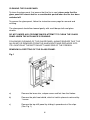
1
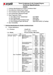
Orchestra
DECORATIVE COAL EFFECT BALANCED FLUE
GAS FIRE
User Instructions
These instructions should be read by the user before operating the
appliance and retained for future reference
Model No’s FBFN76G & FBFN98G are for use on Natural Gas (G20) at a
supply pressure of 20 mbar in G.B. / I.E.
Model No’s FBFP76G & FBFP98G are for use on Propane Gas (G31) at a
supply pressure of 37 mbar in G.B. / I.E.
INSTALLATION INFORMATION
CONDITIONS OF INSTALLATION
It is the law that all gas appliances are installed only by a competent (e.g. CORGI
Registered) Installer in G.B. in accordance with the installation instructions and the
Gas Safety (Installation and Use) Regulations 1998 as amended. Failure to install
appliances correctly could lead to prosecution. It is in your own interest and that
of safety to comply with the law.
The fire may be fitted below a combustible shelf provided that the shelf is at least
200mm above the top of the appliance and the depth of the shelf does not exceed
150mm.
The fire may be installed below combustible shelves, which exceed 150mm deep
providing that the clearance above the fire is increased by 15mm for each 25mm
of additional overhang in excess of 150mm.
If this appliance is fitted directly on to a wall without the use of a fireplace or surround, soft wall coverings such as wallpaper, blown vinyl etc. could be affected by
the heat and may discolour or scorch. This should be considered when installing
or decorating.
The model no. of this appliance is affixed to the control panel and it is
manufactured by:BFM Europe Ltd.
Trentham Lakes
Stoke-on-Trent
Staffordshire
ST4 4TJ
2
ABOUT YOUR NEW ORCHESTRA FIRE
The Flavel Orchestra is a decorative fuel effect balanced flue gas fire incorporates
a unique and highly developed fuel bed which gives the realism of a loose coal
layout combined with realistic flames and glow. The use of durable hard ceramic
material in the construction of the fuelbed components ensures long and trouble
free operation.
When first using the new fire a slight smell may be noticed. This is due to small
deposits of oil on the firebox, but will soon disappear
Please take the time to fully read these instructions as you will then be able to
obtain the most effective and safe operation of your fire.
DO NOT UNDER ANY CIRCUMSTANCES ATTEMPT TO USE THIS APPLIANCE
IF THE GLASS PANEL IS BROKEN OR HAS BEEN REMOVED.
IMPORTANT SAFETY INFORMATION
WARNING : This appliance has a naked flame and as with all heating
appliances a fireguard should be used for the protection of children, the
elderly and infirm. Fireguards should conform to B.S. 8423 : 2002 should be
fitted. (Fireguards for use with gas heating appliances).
Servicing should be carried out annually by a competent person such as a
CORGI registered engineer. It is a condition of the manufacturers guarantee
schemes that this is carried out by a competent person i.e a CORGI
registered Engineer in accordance with these servicing notes
The service should include visually checking the appliance flue terminal for
obstructions.
The condition of the one piece fuelbed should be checked and if necessary the
whole unit should be replaced with a genuine replacement set.
After any servicing work a gas soundness check and spillage test must
always be carried out.
Any debris or deposits should be removed from the fuel bed from time to time.
This may be carried out by referring to the cleaning section as described later in
this book.
Only the fuelbed as supplied must be used and complete and genuine replacements must be used.
3
Always keep furniture and combustible materials well clear of the fire and never
dry clothing or items either on or near to the fire. Never use aerosols or
flammable cleaning products near to the fire when it is in use.
The fuel bed remains hot for a considerable period after use and sufficient
time should be allowed for the fire to cool before cleaning etc.
The fire must only be operated with the fender and ash pan cover supplied and in
position.
OPERATING THE FIRE
The controls are located behind the brass cover below the fender. The controls,
comprise a control valve to adjust the gas flow and a push button piezo igniter. To
light the fire proceed as follows:1)
Depress the control knob and turn anti-clockwise to the position marked pilot.
Hold in the control knob for a few seconds to allow the gas to reach the pilot.
2)
Continue to hold-in the control knob and press the igniter button. If the pilot
does not light, continue to press the igniter button until ignition occurs. The
pilot flame can be seen by looking across the front line of the burner. When
the pilot has lit, continue to hold the control knob in for 5-10 seconds to allow
the thermocouple to heat up, if the pilot goes out when the control knob is
released, repeat the lighting sequence.
After lighting, turn the control knob in the anti-clockwise direction to the high
position and the main burner will light. To gain the most efficient
performance, it is recommended that the control is left in the high position for
5 to 10 minutes
3)
The gas control can be turned clockwise from the maximum position to give
the desired heat output.
4)
To turn the fire off push in and turn the control valve fully clockwise in to the
off position, the burner and pilot will go out.
WHEN TURNING THE FIRE “OFF” PLEASE ENSURE THAT THE CONTROL
VALVE IS TURNED TO THE “OFF” POSITION AND THE PILOT FLAME IS
EXTINGUISHED. DO NOT LEAVE THE PILOT FLAME ONLY LIT.
WARNING : If the fire goes out for any reason or is turned off and it is necessary to re-light the fire it is important to allow the fire to cool for a full 5 minutes before attempting to re-light it.
NOTE : THIS APPLIANCE IS DESIGNED TO WORK SAFELY AND
EFFECTIVELY DURING ADVERSE WEATHER CONDITIONS. HOWEVER,
DURING SUCH TIMES FLAME DISTURBANCE MAY BE NOTICED. THIS IS
NORMAL AND DOES NOT EFFECT OR IMPAIR THE SAFETY OF THE
APPLIANCE.
4
CLEANING
WARNING : Before attempting any cleaning operation ensure that the fire has
been allowed to fully cool.
CLEANING THE TRIM AND PAINTED METAL PARTS
The brass trim fitted to this fire is laquered and will therefore retain it’s looks for the
life of the fire. The ashpan and fret (if supplied with the fire) are also laquered and
may be cleaned in the same way. The brass trim is best cleaned by removing it
from the fire and placing it face up on a flat surface, and wiping with a damp cloth.
The trim is easily replaced by repositioning it on the fire and pushing it back onto
the magnets. After using any metal polish or cleaners the fire should not be used
for 15 minutes or so to allow any cleaning solvents to evaporate.
Black, Stainless steel or Black painted metal parts should be gently cleaned with a
damp cloth also. Abrasive cleaners, chemical cleaning agents or any type of
polish must never be used as damage to the paint may result.
CLEANING THE FUEL BED
We do not recommend cleaning the fuelbed other than at annual service intervals.
If carbon or soot accumulates on the one piece fuelbed, this should be removed
by carefully brushing the fuelbed using a soft brush. For instructions on how to
remove the glass panel please see page 7. The one piece fuelbed is made
from a form of refractory ceramic fibre and should be handled carefully to
avoid generating dust, as this may be harmful if inhaled. As with some
fibrous materials, handling fibrous materials without gloves could cause
skin irritation.
The fuelbed should never be washed or exposed to any cleaning agents or
water.
Any damaged parts must be replaced by contacting your dealer or telephoning
BFM Europe Ltd on the number stated on the rear cover of this book. The fuelbed
must only be replaced with a genuine replacement and the fire must never be run
with a different fuelbed fitted.
The fuelbed must be carefully reassembled as stated in the following section.
5
CLEANING THE GLASS PANEL
To clean the glass panel, first ensure that the fire is cool, please note that the
glass panel will remain hot for a considerable period when the fire has been
switched off.
To remove the glass panel, follow the instructions over page for removal and
re-fitting.
The glass panel should be cleaned gently with a soft damp cloth and glass
cleaner.
DO NOT UNDER ANY CIRCUMSTANCES ATTEMPT TO CLEAN THE GLASS
PANEL WHEN THE APPLIANCE IS RUNNING.
FOLLOWING CLEANING OF THE GLASS PANEL, ALWAYS ENSURE THAT THE
ALLEN KEY IS REMOVED FROM THE ALLEN BOLTS AND REPLACED INTO
ITS LOCATION AT THE BOTTOM LEFT HAND SIDE OF THE FIREBOX.
REMOVING & REFITTING OF THE GLASS FRAME.
Fig. 1
a)
Remove the brass trim, ashpan cover and fret from the firebox.
b)
Remove the pilot heat shield, which is held in place at each end by
1 screw.
c)
Remove the top infill panel by sliding it upwards out of the clips.
(See Fig. 1)
6
d)
Obtain the allen key which is located at the bottom left hand side if
the firebox.
e)
Loosen each allen bolt a small amount at a time to prevent damage
to the glass panel. (See Fig. 1) When all the allen bolts have been
removed, lift away the glass frame and clean
as per the instructions on page 6.
f)
Refit the glass panel to the firebox, again tightening each bolt a
small amount at a time to prevent stressing the glass panel. Fully
tighten all the bolts to ensure good compression on the glass panel
seal.
g)
Refit the brass trim, ashpan & fret to the firebox.
FOLLOWING USE OF THE ALLEN KEY, ALWAYS REMOVE IT FROM THE
FIRE AND REPLACE IT INTO ITS LOCATION IN THE CLIP AT THE BOTTOM
LEFT HAND SIDE OF THE FIREBOX.
REMOVAL / RE-FITTING OF THE FUELBED
FITTING THE FUELBED
Place the fuelbed centrally onto the fuelbed support. Ensure that the fuelbed is
located centrally into the firebox, and that the front outside face of the left and
right-hand fuelbed legs are touching the stainless steel fibre support trims.
See fig. 2 below
Fig. 2
7
Refit the glass frame as detailed in section on page 6, then light the appliance as
detailed on page 4.
USER REPLACEABLE PARTS
The only user replaceable parts on this fire are the fuelbed / coal form, which may
be replaced as described in the above section. Replacement of any other parts
must be carried out by a competent person such as a CORGI registered gas
installer.
The part numbers of the user replaceable parts are as follows, these are available
from specialist spares stockists whose details can be found on our web site,
www.bfm-europe.com, in the ‘stockist’ section.
Fuelbed
70-47800
Due to our policy of continual improvement and development the exact
accuracy of descriptions and illustrations cannot be guaranteed
Part No. B-103920
Issue 3
BFM Europe Ltd.
Trentham Lakes
Stoke-on-Trent
Staffordshire
ST4 4TJ
www.bfm-europe.com
Telephone - Service :
Telephone - General Enquiries :
(0844) 7700169
(01782) 339000