1
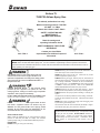
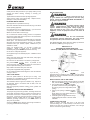
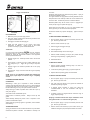
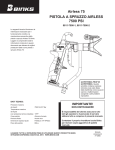
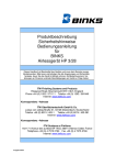
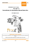
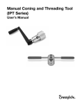
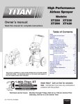
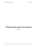
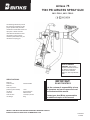
Airless 75
7500 PSI AIRLESS SPRAY GUN
0811-7500-1, 0811-7500-2
The following instructions provide
the necessary information for the
proper operation and preventive
maintenance of the Binks Airless 75
Spray Gun. Please read and
understand all information in this
document in order to get the
maximum performance from your
new Airless 75 spray gun.
PROP 65 WARNING
WARNING: This product
contains chemicals known to
the State of California to
cause cancer and birth
defects or other reproductive
harm.
SPECIFICATIONS:
Maximum
Fluid Pressure:
Maximum
Fluid Temperature
(with heat guard installed)
Gun Body:
Fluid Path:
175ºF
Forged Aluminum
Stainless Steel
Fluid Inlet Size:
1/4” NPS(m) Thread
Gun Weight:
660 g
IMPORTANT!
DO NOT DESTROY
7500 Psi/517Bar
It is the customer’s responsibility to have
all operators and service personnel read
and understand this manual.
Contact your local Binks representative
for additional copies of this manual
READ ALL INSTRUCTIONS BEFORE OPERATING THIS BINKS PRODUCT
INSTRUCTIONS ALSO AVAILABLE ON WWW.BINKS.COM
Part Sheet
77-2950
Trigger Lock Positions
NOTES
14 inches.
Excessive fluid pressure will distort the spray pattern. Spray at
the lowest acceptable pressure.
Hour-glass and tails on spray patterns normally indicate too low a
fluid pressure for the nozzle tip orifice size or the material is too
viscous or thick. Increase the pressure or thin the material.
Distorted patterns may be the result of worn or plugged tips.
Clean (see tip clogs) or replace the spray tip.
Airless spray guns are either on or off. You cannot feather with
airless guns as you can with air atomized equipment.
LOCKED
UNLOCKED
GUN OPERATION
1. Make sure your tip is in the spray position.
2. Start your sprayer following the instructions provided in the
equipment owner’s manual.
3. Pull trigger to achieve flow through gun.
Successive strokes may require overlapping. Typical overlap is
30%.
TO REPLACE NEEDLE ASSEMBLY (11)
1. Shut off power supply to pump and release pressure from
gun. Remove gun from hose.
2. Remove screws and rear cap. (15)
4. Adjust the fluid pressure on the sprayer until proper
atomization is achieved.
Always spray at the lowest
pressure necessary to get the desired atomization.
3. Remove trigger and trigger stud (10)
TIP CLOGS
4. Unscrew gland nut.
If you are using a Genuine BINKS
spray tip, follow the
instructions below to clear a clogged tip. If you are using a
different tip, follow the instructions included in the equipment
manual provided with that tip.
5. Pull needle assembly out from back of gun.
7. Reinsert needle assembly (of step 5) into position through
back of gun body assembly. Tighten gland nut.
1. Engage Trigger Lock. Rotate tip handle 180° to the reverse
position.
8. Reassemble items.
2. Unlock trigger. Point the gun into a bucket holding the gun
nose away from you. Trigger the gun briefly to expel the
clog.
TO REPLACE PACKING
3. Engage Trigger Lock. Rotate tip handle 180° to the spray
position.
4. Unlock trigger. Spray a test to be sure the clog is completely
expelled.
1. Remove needle assembly following steps 1-5 under ’To
Replace Needle Assembly’.
2. Locate slot in packing gland (12), pry apart and push off.
3. Replace with new packing gland, and reassemble.
NOTE: If clog is not completely expelled after following the
above steps, repeat steps 1-4 until the clog is completely
cleared.
TO ADJUST PACKING GLAND
CLEANING AND MAINTENANCE
1. Shut off power supply to pump and release pressure from
gun. Remove gun from hose.
CLEAN DAILY
Maintaining a clean gun is important to ensure trouble-free
operation and extend the service life of your gun. Always flush the
gun thoroughly after each use and store in a warm, dry location.
DO NOT leave the gun or any of its parts in water or solvents.
Always flush gun outside if possible and at least 25 ft (7.5 m)
away from sprayer.
Area must be free of flammable vapors.
Always flush at minimum pressure.
guard.
Always remove tip and
Static electricity buildup may result in fire or explosion in the
presence of flammable vapors.
Always hold the gun firmly against a grounded, metal container
when flushing.
TROUBLESHOOTING
Spray gun distance from work surface should be at a point where
maximum fan pattern is evident. This distance is normally 8 to
2. Use 7/16’ open-end wrench to turn gland nut clockwise to
eliminate any leakage at gland.
3. If sluggish trigger operation is noted, turn gland nut
counterclockwise in 1/16 turn increments until drag is
eliminated.
4. If leakage cannot be stopped without excessive drag on
trigger, replace packing.
Spraying of heated materials will require installation of the
heat guard 54-7527. To install the heat guard (16):
1. Shut off power supply to pump and release pressure from
gun. Remove gun from hose.
2. Remove screws and bracket (17) from bottom of the gun.
Install the heat guard (16) and replace bracket and screws.
5
2
Airless 75
7500 PSI Airless Spray Gun
For trained, professional use only!
Maximum working pressure: 7500 PSI
– 517 BAR – 51.7 Mpa
Models 0811-7500-1 & 0811-7500-2
SAFETY, OPERATING AND
MAINTENANCE
INSTRUCTIONS INSIDE!!
Read all warnings and
operating information inside
SAVE THIS MANUAL FOR FUTURE
REFERENCE
0811-7500-2
Contact your local Binks
representative for Additional copies of
this manual
0811-7500-1
The following instructions provide the necessary information for other operation and preventative maintenance of the
BINKS Airless 75 7500 PSI Airless Spray Gun. It is the customer’s responsibility to have all operators and service
personnel read and understand this manual. Please read and understand all information in this document in order to
safely operate your new spray gun.
EYE HAZARD: Failure to wear safety glasses with side
shields could result in serious injury or blindness. All
operators and bystanders must always wear safety glasses
with side shields that conform to ANSI Standard Z87.1 or
European Norm 156.
HAZARD: INJECTION INJURY – a high pressure stream
produced by this equipment can pierce the skin and
underlying tissues, leading to a serious injury and possible
amputation. See a physician immediately.
DO NOT TREAT AN INJECTION INJURY AS A SIMPLE CUT!
Injection can lead to amputation. See a physician immediately.
HAZARD: BURN HAZARD: When using the Airless 75 with a
fluid heater, equipment surfaces can become very hot.
ALWAYS use heat guard 54-7527 when spraying heated
materials. Do not exceed 175°F fluid temperature. Do not
exceed manufacturer recommended fluid temperature.
SAFETY PRECAUTIONS:
KEEP CLEAR OF NOZZLE: Do not exceed maximum working
pressure of 7500 PSI (517 BAR, 51.7 Mpa). The maximum
operating range of the gun is 7500 PSI/517 BAR fluid pressure.
PREVENTION:
NEVER Aim the gun at any part of the body.
NEVER Allow any part of the body to touch the fluid stream. DO
NOT allow body to touch a leak in the fluid hose.
NEVER Put hand in front of the gun. Gloves will not provide
protection against an injection injury.
ALWAYS lock the gun trigger, shut the pump off, and release all
pressure before servicing, cleaning the tip or guard, changing the
tip, or leaving unattended. Pressure will not be released by
turning off the motor. The PRIME/SPRAY valve must be turned
to PRIME to relieve the pressure. Refer to the PRESSURE
RELIEF PROCEDURE described in the pump manual.
ALWAYS Keep the tip guard in place while spraying. The tip
guard provides some protection, but is mainly a warning device.
ALWAYS Remove the spray tip before flushing or cleaning the
system.
The paint hose can develop leaks from wear, kinking, and abuse.
A leak can inject material into the skin. Inspect the hose before
each use.
NEVER Use a spray gun without a trigger lock and trigger guard
in place and in good working order.
All accessories must be rated at 7500 PSI (517 BAR) or higher.
This includes spray tips, guns, extensions, and hose.
NOTE TO PHYSICIAN:
Injection into the skin is a traumatic injury. It is important to treat
the injury as soon as possible. DO NOT DELAY treatment to
research toxicity. Toxicity is a concern with some coatings
injected directly into the blood stream. Consultation with a
plastic surgeon or reconstructive hand surgeon may be
advisable
2
3
HAZARD EXPLOSION OR FIRE – Solvent and paint fumes
can explode or ignite. Severe injury and/or property damage
can occur.
PREVENTION:
Provide extensive exhaust and fresh air introduction to keep the
air within the spray area free from accumulation of flammable
vapors.
Avoid all ignition sources such as static electricity sparks,
electrical appliances, flames, pilot lights, hot objects, and sparks
from connecting and disconnecting power cords or working light
switches.
Do not smoke in spray area.
Fire extinguisher must be present and in good working order.
Place pump at least 25 feed (7.6 m) away from the spray object
in a well ventilated area.
Add more hose if necessary.
Flammable vapors are often heavier than air. Floor area must be
extremely well ventilated. The pump may contain arcing parts
that emit sparks and can ignite vapors.
The equipment and objects in and around the spray area must
be properly grounded to prevent static sparks.
Use only conductive or grounded high pressure fluid hose. Gun
must be grounded through hose connections.
Power cords must be connected to a grounded circuit.
Always flush unit into a separate metal container, at low pump
pressure, with spray tip removed. Hold gun firmly against side of
container to ground container and prevent static sparks.
Follow the material and solvent manufacturer’s warnings and
instructions.
Use extreme caution when using materials with a flashpoint
below 70° F (21° C). Flashpoint is the temperature that a fluid
can produce enough vapor to ignite.
Plastic can cause static sparks. Never hang plastic to enclose a
spray area. Do not use plastic drop cloths when spraying
flammable materials.
Use lowest possible pressure to flush equipment
HAZARD: EXPLOSION HAZARD DUE TO INCOMPATIBLE
MATERIALS – will cause severe injury or property damage.
PREVENTION:
Do not use materials containing bleach or chlorine.
Do not use halogenated hydrocarbon solvents such as bleach,
mildewcide, methylene, chloride and 1,1,1 ’ trichloroethane.
They are not compatible with aluminum.
Contact your coating supplier about the compatibility of material
with aluminum.
HAZARD: HAZARDOUS VAPORS – Paints, solvents,
insecticides, and other materials can be harmful if inhaled or
come in contact with the body. Vapors can cause severe
nausea, fainting, or poisoning.
PREVENTION:
Use a respirator or mask if vapors can be inhaled. Read all
instructions supplied with the mask to be sure it will provide the
necessary protection.
Wear protective eyewear.
Wear protective clothing as required by coating manufacturer.
HAZARD: GENERAL – Can cause severe injury or property
damage.
PREVENTION:
Read all instructions and safety precautions before operating
equipment.
Always disconnect the motor from the power supply before
working on the equipment.
Follow all appropriate local, state and national codes governing
ventilation, fire prevention, and operation.
The United States Government Safety Standards have been
adopted under the Occupational Safety and Health Act (OSHA).
These standards, particularly part 1926 of the Construction
Standards should be consulted.
Use only manufacturer authorized parts. User assumes all risks
and liabilities when using parts that do not meet the minimum
specifications and safety devices of the pump manufacturer.
Before each use, check all hoses for cuts, leaks, abrasion, or
bulging of cover. Check for damage or movement of couplings.
Immediately replace the hose if any of these conditions exist.
Never repair a paint hose. Replace it with another grounded
high-pressure hose.
All hoses, swivels, guns, and accessories must be pressure rated
at or above the maximum operating pressure range of the airless
sprayer.
Do not spray outdoors on windy days.
Wear protective clothing to keep paint off skin and hair.
The following are general WARNINGS related to the setup,
use, grounding, maintenance and repair of this equipment.
FIRE AND EXPLOSION HAZARD – Flammable fumes, such
as solvents and paint fumes, in work area can ignite or
explode. To help prevent fire and explosion:
Use equipment only in well ventilated area. Provide fresh air
ventilation to avoid the buildup of flammable fumes from the
material being sprayed or from the solvent.
Eliminate all ignition sources; such as pilot lights, cigarettes,
portable electric lamps, and plastic drop cloths (potential static
arc).
Keep work area free of debris; including solvent, rags, and
gasoline.
Sprayers generate sparks. When flammable liquid is used in or
near sprayer or for flushing or cleaning, keep sprayer at least 25
feet (7.6m) away from explosive vapors.
Electrically disconnect all equipment in the spray area. Do not
plug or unplug power cords or turn lights on or off when
flammable fumes are present.
Ground equipment and conductive objects in work area. Ground
object being sprayed.
If there is static sparking or you feel a shock, stop operating
immediately. Do not use equipment until you identity and
correct the problem.
Keep a fire extinguisher in the work area.
SKIN INJECTION HAZARD
High pressure fluid from spray gun, hose leaks, or ruptured
components will pierce skin. This may look like just a cut, but is
a serious injury that can cause amputation. Seek immediate
surgical treatment. Inform the physician as to what type of
material was injected.
Do not point gun at anyone or any part of the body.
Do not put your hand or fingers over the spray tip.
Do not stop or deflect leaks with your hand, body, glove or rag.
Do not spray without tip guard installed.
Engage trigger lock when not spraying.
3
4
Follow pressure relief procedure for your sprayer when you stop
spraying and before cleaning, checking or servicing your
equipment.
SET UP INSTALLATION
Tighten all fluid connections before operating equipment.
Never attempt to assemble, change, or clean the gun, tip, or
tip guard without first relieving pressure from the spray
system. Follow the “PRESSURE RELIEF PROCEDURE” in
the sprayer’s equipment manual.
Check all hoses, tubes, and couplings daily. Replace all worn,
damaged, or loose parts immediately.
EQUIPMENT MISUSE HAZARD
This equipment is for professional use only.
Read and understand all instructional manuals, tags, and labels
before operating equipment.
Use equipment only for its intended purpose. If you are unsure
of its purpose, call your local BINKS distributor.
Misuse can cause death or serious injury.
Do not exceed the maximum working pressure or temperature
rating of the lowest rated system component. See the technical
data in all equipment manuals.
Use fluids and solvents that are compatible with your equipment
wetted parts. See technical data in all equipment manuals.
Read fluid and solvent manufacturer’s warnings. For complete
information about your material, request a MSDS from your
distributor or retailer.
Check your equipment daily. Do not alter or modify your
equipment.
Repair or replace worn or damaged parts
immediately with genuine BINKS Replacement Parts only.
Always use tip safety guard for added protection against
injection. Beware that the guard alone will not prevent
injection. NEVER cut off tip guard! Always engage gun
trigger lock when the gun is not in use. Before servicing
equipment, consult all equipment manuals and follow all
warnings.
Do not allow fluid to exceed the fluid manufactures
recommended maximum temperature. Gun must include
heat guard (54-7527) to be used with heated materials.
Note: BINKS
Airless Spray Gun Safety Tip Guards for
the 7500 PSI (517 BAR) gun are gray in color.
BINKS Airless 75
PROFESSIONAL AIRLESS SPRAY GUN
7500 PSI (517 BAR) MODEL 0811-7500-1 AND 0811-7500-2
Do not alter or modify this equipment.
Use equipment only for its intended purpose. Call Binks for more
information.
Safety
Guard
Route hoses and cables away from traffic areas, sharp edges,
moving parts and hot surfaces.
Do not kink or over bend hoses or use hoses to pull equpment.
Use genuine BINKS
hoses. If provided, do not
remove the spring guards from hoses, these are on the hoses to
prevent rupture from kinking at the connectors.
Trigger Lock
Trigger
Keep children and animals away from work area.
Comply with all applicable safety regulations.
Do not operate equipment when fatigued or under the influence
of drugs or alcohol.
TOXIC FLUID HAZARD
Know the specific hazards of the fluid you are using. This
information is on the MSDS for the material that is being used.
Read all fluid manufacturer’s warnings.
Store hazardous fluids in approved containers only. Dispose of
all hazardous fluids in accordance with all state, local and
national guidelines.
Wear the appropriate protective clothing, gloves, eyewear and
respirator.
GROUNDING AND ELECTRIC REQUIREMENTS
The sprayer and gun must be grounded. Grounding reduces the
risk of static and electric shock by providing an escape wire for
the electrical current due to static build up or in the event of a
short circuit. Follow the grounding instructions included in the
equipment manual provided with all your spray equipment.
Additional grounding instructions for your BINKS Airless 75
Spray Gun are provided:
Ground your BINKS Airless 75 Spray Gun through connection to
a properly grounded fluid hose and pump.
1/4 - 18 NPS thread
If you are using a genuine BINKS
tip, follow the
instructions below to install the guard and tip. If you are using a
different tip, follow the installation instructions provided with the
tip that you are using.
INSTALLATION OF THE TIP AND GUARD
1. Make sure that the tip and tip guard are rated for use at 7500
PSI. (Genuine BINKS
parts will be gray in color.)
2. Use seal alignment tool on BINKS
tip handle to insert seal and pressure gasket
into back of guard, turn to align with tip shaft
opening.
3. Insert tip into opening on BINKS
guard.
NOTE: Narrow end of tip handle should be in
forward position for spraying.
4. Thread the guard onto gun head until it stops.
Tighten slightly with wrench ’ DO NOT OVER
TIGHTEN.
CONNECTION TO THE HOSE
Attach a properly grounded fluid hose to the fluid hose
connection fitting (1/4 ’ 18 NPS thread) on the bottom of the
handle of your spray gun. Use two (2) wrenches ’ one on the gun
and one on the hose. Tighten securely.
4
5
Trigger Lock Positions
14 inches.
Excessive fluid pressure will distort the spray pattern. Spray at
the lowest acceptable pressure.
Hour-glass and tails on spray patterns normally indicate too low a
fluid pressure for the nozzle tip orifice size or the material is too
viscous or thick. Increase the pressure or thin the material.
Distorted patterns may be the result of worn or plugged tips.
Clean (see tip clogs) or replace the spray tip.
Airless spray guns are either on or off. You cannot feather with
airless guns as you can with air atomized equipment.
LOCKED
UNLOCKED
GUN OPERATION
1. Make sure your tip is in the spray position.
2. Start your sprayer following the instructions provided in the
equipment owner’s manual.
3. Pull trigger to achieve flow through gun.
Successive strokes may require overlapping. Typical overlap is
30%.
TO REPLACE NEEDLE ASSEMBLY (11)
1. Shut off power supply to pump and release pressure from
gun. Remove gun from hose.
2. Remove screws and rear cap. (15)
4. Adjust the fluid pressure on the sprayer until proper
atomization is achieved.
Always spray at the lowest
pressure necessary to get the desired atomization.
3. Remove trigger and trigger stud (10)
TIP CLOGS
4. Unscrew gland nut.
If you are using a Genuine BINKS
spray tip, follow the
instructions below to clear a clogged tip. If you are using a
different tip, follow the instructions included in the equipment
manual provided with that tip.
5. Pull needle assembly out from back of gun.
7. Reinsert needle assembly (of step 5) into position through
back of gun body assembly. Tighten gland nut.
1. Engage Trigger Lock. Rotate tip handle 180° to the reverse
position.
8. Reassemble items.
2. Unlock trigger. Point the gun into a bucket holding the gun
nose away from you. Trigger the gun briefly to expel the
clog.
TO REPLACE PACKING
3. Engage Trigger Lock. Rotate tip handle 180° to the spray
position.
4. Unlock trigger. Spray a test to be sure the clog is completely
expelled.
1. Remove needle assembly following steps 1-5 under ’To
Replace Needle Assembly’.
2. Locate slot in packing gland (12), pry apart and push off.
3. Replace with new packing gland, and reassemble.
NOTE: If clog is not completely expelled after following the
above steps, repeat steps 1-4 until the clog is completely
cleared.
TO ADJUST PACKING GLAND
CLEANING AND MAINTENANCE
1. Shut off power supply to pump and release pressure from
gun. Remove gun from hose.
CLEAN DAILY
Maintaining a clean gun is important to ensure trouble-free
operation and extend the service life of your gun. Always flush the
gun thoroughly after each use and store in a warm, dry location.
DO NOT leave the gun or any of its parts in water or solvents.
Always flush gun outside if possible and at least 25 ft (7.5 m)
away from sprayer.
Area must be free of flammable vapors.
Always flush at minimum pressure.
guard.
Always remove tip and
Static electricity buildup may result in fire or explosion in the
presence of flammable vapors.
Always hold the gun firmly against a grounded, metal container
when flushing.
TROUBLESHOOTING
Spray gun distance from work surface should be at a point where
maximum fan pattern is evident. This distance is normally 8 to
2. Use 7/16’ open-end wrench to turn gland nut clockwise to
eliminate any leakage at gland.
3. If sluggish trigger operation is noted, turn gland nut
counterclockwise in 1/16 turn increments until drag is
eliminated.
4. If leakage cannot be stopped without excessive drag on
trigger, replace packing.
Spraying of heated materials will require installation of the
heat guard 54-7527. To install the heat guard (16):
1. Shut off power supply to pump and release pressure from
gun. Remove gun from hose.
2. Remove screws and bracket (17) from bottom of the gun.
Install the heat guard (16) and replace bracket and screws.
5
6
Item No.
1
2
3
4
5
6
7
9
10
11
12
14
15
16
17
18
Part No.
1108-75B
54-7511-K
54-2096-K5
54-7518-K
54-7523-K
72-792
20-5865-K3
54-7534-K
54-7512
54-2949
54-7508
54-7530-K
54-7527
54-7510-K
54-7519-K
Description
Twist Tip 7500 psi, see chart
7500 psi Twist Tip Guard
Diffuser Nut Kit
Washer (Kit of 5)
Fluid Tube Assembly kit
Gun Head Kit
Inlet Adapter
Set Screw (Kit of 3)
Trigger Kit
Needle Assembly
Packing Gland
Spring
Rear Cap Kit
Heat Guard (Accessory)
Bracket Kit
Hose Retainer
Quantity
1
1
1
1
1
1
1
1
1
1
1
1
1
1
1
0811-7500-1 only.
0811-7500-2 only.
6
7
BINKS
BINKS
SPRAY TIP
SELECTION CHART
PART NUMBER 9-XXX-75 (Tips rated for use at 7500 psi)
All of the following tips will have a grey tip handle
4”
spray
pattern
.007" orifice
.009" orifice
.011" orifice
.013" orifice
.015" orifice
.017" orifice
.019" orifice
.021" orifice
.023" orifice
.025" orifice
.027" orifice
.031" orifice
.035" orifice
211
213
215
217
6”
spray
pattern
307
309
311
313
315
317
8”
spray
pattern
10”
spray
pattern
409
411
413
415
417
419
421
509
511
513
515
517
519
521
523
525
12”
spray
pattern
435
611
613
615
617
619
621
623
625
627
631
635
14”
spray
pattern
713
715
717
ORDER
NUMBER
72-2332
72-2333
72-2340
72-2341
54-1836
54-1835
52-5208
52-5209
72-2339
ACCESSORIES
DESCRIPTION
Swivel Adapter 1/4” M x 1/4” F
Swivel Adapter 3/8” M x 1/4” F
Swivel Adapter with inlet filter (60 Mesh)
Swivel Adapter with inlet filter (100 Mesh)
60 Mesh filter
100 Mesh filter
30” Airless Tip Extension
60” Airless Tip Extension
High Pressure “Y” Block (7,250 psi max)
BINKS
ORDER
NUMBER
71-4870
71-4840
71-4841
71-4860
71-4861
AIR HOSE
DESCRIPTION
Hose Whip 1/4” F x 3/8” M 3 ft,
10,000 psi working pressure
Hose 1/4” x 25 ft 10,000 psi working pressure
Hose 1/4” x 50 ft 10,000 psi working pressure
Hose 3/8” x 25 ft 8,000 psi working pressure
Hose 3/8” x 50 ft 8,000 psi working pressure
The Spray Gun models listed in the following declaration of conformity may be used in some potentially explosive atmospheres ONLY when
the special conditions for safe installation and operation have been followed as expressed in this user manual (Part Sheet). These models
are approved to ATEX regulations 94/9/EC, protection level: II 2 G X: Suitable for use in Zones 1 and 2.
EC Declaration of Conformity
Manuf. By:Binks
195 Internationale Blvd.
Glendale Heights, IL 60139
Type/Series: Handheld Spray Guns
Model: 0811-7500-1, 0811-7500-2
The equipment to which this document relates is in conformance with the following standards or other normative references:
EN ISO 12100-1&2:2003 and BS EN 1953:1999 and thereby conform to the protection requirements of Council Directive
2006/42/EC relating to Machinery Safety Directive, and;
EN 13463-1:2001, Council Directive 94/9/EC relating to Equipment and Protective Systems for use in Potentially Explosive
Atmospheres, protection level II 2 G X.
Approved By: _______________ Date: 12/1/2011
Doug Taylor, Binks
WARRANTY
This product is covered by Binks’ 1 Year Limited Warranty.
Binks Worldwide Sales and Service Listing: www.binks.com
North American Office
Binks
195 Internationale Blvd.
Glendale Heights, IL 60139
630-237-5000
www.binks.com
Toll Free Customer Service
and Technical Support
800-992-4657
Toll Free Fax
888-246-5732
1/12 © 2012 Binks All rights reserved.
Binks European Sales and Service Listing: www.itwifeuro.com
ITW Industrial Finishing
Binks has authorized distributors throughout the world. For technical assistance or the distributor nearest you, see listing below.
ITW Industrial Finishing:
Ringwood Road, Bournemouth
BH11 9LH England
Tel: +44(0) 1202 571111
Fax: +44(0) 1202 573488
Email: [email protected]
ITW Surfaces et Finitions:
163-171 Av des Auréals
26014 Valence cedex France
Tel: +33 4 75 75 27 00
Fax: +33 4 75 75 27 59
Email: [email protected]
ITW Oberflächentechnik GmbH:
Justus-von-Liebig-Straße 31
D-63128 Dietzenbach Germany
Tel: +49 (0) 6074-403-1
Fax: +49 (0) 6074-403-300
Email: [email protected]
1/12 © 2012 ITW Industrial Finishing All rights reserved. Printed in Mexico.