1
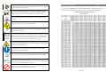
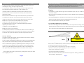
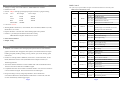
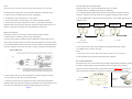
Vesta
RGB MULTI-COLOR ANIMATION LASER SHOW SYSTEM
User's Manual
Read this manual before using. Do not attempt to open the housing or repair
this device by yourself without contact us!
General instructions
Vesta
Unpacking:
Thank you for purchasing this product. Please read user guide for safety and before using
the product. Keep this manual for future reference. This product can create perfect laser
programs and effects since it has passed a series of strictly tests before delivery. Please check
the attachments listed on the page after opening the carton. Immediately upon receiving
a fixture, carefully unpack the box. Check the box contents to ensure that all parts are present
and that they are in good condition. If any part appears damaged from shipping, or if the
box shows signs of mishandling, notify the shipper immediately. In addition, retain the box
and all the packing material for inspection.In any event, save the carton and all packing material
because, in case that you have to return the fixture to the factory, you will have to do so in its
original box, with its original packing.
1. Laser Light:
1PCS
2. Power Cable:
1PCS
3. User Guide:
1PCS
Safty Notice:
Please read the following notes carefully because they include important safety information
about the installation,usage and maintenance of this product. It is important to read all these
notes before starting to work with this product.
Lasers can be hazardous and have unique safety considerations. Permanent eye injury and
blindness is possible if lasers are used incorrectly. Pay close attention to each safety REMARK and
WARNING statement in the user manual. Read all instructions carefully BEFORE operating this
device.
There are no user serviceable parts inside the light. Any reference to servicing this unit you
may find from now on in this User Manual will only apply to properly C we certified
technicians. Do not open the housing or attempt any repairs unless you are one of them.
Please refer to all applicable local codes and regulations for proper
installation of the light.
Keep this manual for future consultation. If you sell the light to another user,
make sure that they also receive this manual.
Page 1
Avoid direct eye exposure to the light source while the fixture is on. Always disconnect
the light from its power source before servicing. Always connect the light to a grounded
circuit to avoid the risk of electrocution.
This product is for indoor use only! Use only in dry locations. Keep this
device away from rain and moisture, excessive heat, humidity and dust. Do
not allow contact with water or any other fluids, or metallic objects.
DMX Address Chart
Vesta
This chart lists the DMX dipswitch setting for DMX address 1 through 511. Follow the
instructions below to configure fixture dipswitches with you desired DMX address.
DMX Address Quick Reference Chart
DipSwitch Position
Make sure there are no flammable materials close to the fixture(s) while
operating.
Please prevent this light away from electrical shock
When hanging this fixture, always secure it to a fastening device using a
safety cable (not provided).
Power
110V 240V
Ground
Always make sure that you are connecting the light to the proper voltage, as per the
specifications in this manual or on the product's sticker. Never connect the light to a
dimmer pack. Make sure that the power cable is not cracked, crimped or damaged.
Never disconnect the fixture by pulling or tugging on the power cable.
The maximum ambient temperature (Ta) is 104 F (40 C). Do not operate the
fixture at a higher temperature. In case of a serious operating problem, stop
using this product immediately!
Use cleaning tissue to remove the dust absorbed on the external lenses
periodically to optimize light output.
Do not remove or break the warranty label, otherwise it void the warranty.
Always replace with the exact same type fuse, replacement with anything
other than the specified fuse can cause fire or electric shock and damage your
unit, and will void your manufactures warranty.
There are no serviceable parts in the light. Please have all servicing and
adjustments made by a qualified service engineer.
Page 2
DipSwitch Position
DMX Address
Page 11
Troubleshooting
Vesta
1. If the power supply indicator doesn't light up and the laser doesn't work, please
check the power supply, the input voltage and the fuse.
Laser Safty Warnings
Vesta
Potential laser injury hazard exists with this product! Read these Instructions carefully,
which include important information about installation, safe use and service!
2. In Stand-Alone operation, if the power supply indicator is light up and sound
active indicator isn't light up, but the laser is shut off doesn't work.
Caution
A. Because sound is too small make for laser shut off in sound active, please
* Avoid direct eye contact with laser light. Never intentionally expose your eyes or others to
increase the music volume or increase audio sensitivity with sensitivity knob,
please check as below.
direct laser radiation.
*This laser product can potentially cause instant eye injury or blindness if laser light directly
B. Please check if unit has been set up in slave mode, then set up in master mode.
3. In Master-Slave operation, slave unit don't function, please check as below.
A. Make sure to there's only one master in the chain, and the others are set in slave mode.
B. Make sure to control the unit without DMX console controlling.
strikes the eyes.
*It is illegal and dangerous to shine this laser into audience areas, where the audience or other
personnel could get direct laser beams or bright reflections into their eyes.
*It is a US Federal offense to shine any laser at aircraft.
C. Make sure to take a good quality power cable and connection.
4. In DMX mode operation, the laser is OFF and the DMX signal indicator is
NON-INTERLOCKED HOUSING WARNING
unlighted, please check as below.
*This unit contains high power laser devices internally. Do not open the laser housing, due to
A. Make sure to set up the DMX mode.
potential exposure to unsafe levels of laser radiation. The laser power levels accessible if the
B. Make sure to have a good connection.
unit is opened can cause instant blindness, skin burns and fires.
5. In DMX operation, the unit can’t be controlled by the DMX console, but the DMX signal
indicator is flashing, please make sure the DMX console and unit have the same channel.
Installation
Vesta
6. If the unit is fail, please turn off the unit, then turn on again after 5 minutes.
Warranty Warnings:
1. Damages caused by the disregard of this user manual are not subject to Warranty.
AVOID EYE DIRECT
CONTACT!
The dealer will not accept liability for any
2. Please consider that unauthorized modifications on the device are forbidden due to
safety reasons. Please note that damages caused by manual modifications on the
*Laser effects projected 3 meters (9.8 ft) above the audience are eye safe. A survey should be
device or unauthorized operation by unqualified persons are not subject to warranty.
taken to assess the likelihood of any reflective surfaces (such as high windows, chrome bars
3. If this device will be operated in any way different to the one described in this
etc) bouncing stray beams back down into the audience.
manual, it may suffer damages and the guarantee becomes void. Furthermore, any
*Using a fastening clamps on the light and tight to the ceiling in a strong hook..
other operation may lead to dangers like short-circuit, burns electric shock, etc.
*Make sure its correct power output and plug the power cable to the wall socket.
* Power must be in earth! Power on the light.
After trying the above solution you still have a problem, please contact your dealer
or our company for service.
* Do not shoot the beams to the audience!
*Do not look direct into the laser aperture once the laser light is ON. Please pay attention to
the Laser Danger Warning Sticker!
Page 10
Page 3
Technical Specification
Vesta
1. Voltage: bi-voltage 110V -220V-250V AC, 50HZ-60HZ/ Fuse: 2A/250V
2. Rated Power: 50W
3. Scanner: 25Kpss scanning speed, High-speed optical scanner, big angle scanning
4. Laser:
Color
Wavelength
DMX Control
The system only accepts the DMX512 signal of international standard to control the system.
DMX Control Parameter Chart
Channel
Function
Value
Power output
Red
650nm
500mW
Green
532nm
200mW
Blue
450nm
300mW
Mixed white:
1000mW
CH1
Mode
Description
0~49
Sound Active mode
50~99
Auto-Beam mode
100~149 Auto-Animation mode
150~199 Manual mode to Auto run
200~255 Manual mode to Sound Active run
5. Laser class: Class IV
Closed-W-R-Y-G-B-P-fixed color
5. Working Modes: Sound Active, AUTO-Beam, AUTO-Animation, DMX512 (12 CH),
CH2
Dimmer
0~255
-random single color-random seven-color
-moving seven-color-fixed color
Master/Slave, PC Control
6. Graphics & Effects: 128 beam show and animated graphics show patterns
CH3
Pattern Select 0~255
0~127
7. Interface: 3 pins XLR jack for DMX or Maser-Slave linking
CH4
DB25/M ILDA computer interface for PC control
Moving-Y
128 pattrens
Manual to up to down moving
128~191 Auto to down moving
192~255 Auto to up moving
8. Size: 600*470*290mm
0~127
9. Weight: 6.5Kg
CH5
Moving-X
Manual to left to right moving
128~191 Auto to right moving
192~255 Auto to left moving
Features
Vesta
CH6
Rolling-X
1. RGB full-color animation laser with high-speed optical scanner to create animated
graphics,128 beam show and graphics show patterns, and with the function of unique
0~127
128~255 Auto rolling
CH7
Rolling-Y
0~127
Manual rolling
128~255 Auto rolling
blanking, frequently flashing, rotating, moving, rotation, split, zoom, drawing, speed
and color etc.
0~127
2. Includes six working modes as DMX512, Sound Active, AUTO-Animation, AUTO-
Manual rolling
CH8
Rotation
Manual rotation
128~191 Auto clockwise rotation
Beam, Master/Slave and PC control(with DB25 ILDA computer interface) for
192~255 Auto counter clockwise rotation
different applications.
0~85
Auto zoom(+)
86~170
Auto zoom(-)
3. The unit has fourteen channels to control in DMX mode. The unit has BLACK OUT
CH9
Zoom(+/-)
CH10
Pattern Size
0~255
0 is Moderate, 1 is small, 255 is big
CH11
Display Dot
0~255
0 is display dot, 255 is best brightness
CH12
Drawing
0~127
Auto drawing mode 1
128~255
Auto drawing mode 2
171~255 Manual zoom(+/-)
function. The uint will shut off if no DMX512 signal.
4. Compatible ILDA laser show software with ILDA interface. Use electronic switches to
conversion full ILDA signal. The uint will shut off if no ILDA signal.
5. Design according to security and good performance, safer to human and
environment. Master/Slave mode, DMX512 mode and PC Control mode, will shut
off laser automatically without trigger signal.
Page 4
Page 9
Front/Rear Panel
DMX Control
Vesta
The system only accepts the DMX512 signal of international standard to control the
system mode, the laser beam ON /OFF, running direction, running speed and twinkle
1
speed etc.
Function setting
If it is set to ILDA mode (use PC software to control laser light), just need to connect ILDA
signal to DB25 jack. If set to Built-in program, then ILDA signal cannot be connected,seting
dipswitches directly is ok. ILDA mode (PC control) and Built-in program mode can be
identified and transisted automatically.
0=OFF 1=ON X=OFF or ON
Front Panel Figure
1. Laser aperture
5
4
6
1
DIPSWITCH CHART
2
3
11
FUNCTION
#1 #2 #3 #4 #5 #6 #7 #8 #9 #10
0
0
0
X
X
X
X
X
X
0 SOUND ACTIVE
1
0
0
X
X
X
X
X
X
0 AUTO-BEAM
1
1
0
X
X
X
X
X
X
0 AUTO-ANIMATION
0
0
1
X
X
X
X
X
X
0 SLAVE MODE
SET DMX ADDRESS
1 DMX MODE
Built-In Program Function Chart
9
DMX address calculation
For DMX mode, DMX address from #1 to 9# dipswitches must be set, the address is set
10
Rear Panel Figure
1. Sound active microphone
from 1 to 511. Each dipswitch represents a binary value.
8
7
2. Sound active indicator:Blue
Dipswitch
#1
#2
#3
Value
1
2
4
Dipswitch
#6
#7
#8
Value
32
64
128
3. Power indicator:Red
4. Audio sensitivity knob
5. Function of built-in program setting dipswitches 6. X Pattern size knob
7. Y Pattern size knob
8. ILDA IN/OUT interface with DB25 jack
9. DMX or linking jack
10. Power switch ON/OFF
#4
8
#9
256
11. Power jack
#5
16
#10
DMX, Set to "0"
One unit has 5 channels, so each unit must be assigns 5 channels at least. We may
assign 8 channels for one unit, then DMX address = 8*N + 1, N=0, 1, 2, 3 …… Example,
One loop address=1, two loop address=9, three loop address=17, four loop address=25
Loop
Address
Binary
Dipswitches
1
1
100000000
#1
2
9
100100000
#1+#4
3
17
100010000
#1+#5
4
25
100110000
#1+#4+#5
Function & Setting
Vesta
Sound Active
The change of the laser pattern is controlled by sound, that is, the rhythm of the sound
control the effect of the changing laser pattern. Turning the sensitivity knob in the
clockwise direction to increase the fixture’s sensitivity to sound, the knob in the counter
clockwise direction to decrease. The laser diode will automatically turn off after 8
seconds when the music stops.
The dipswitches setting for DMX address see the " DMX Address Quick Reference Chart ".
Page 8
Page 5
AUTO
Universal DMX Operation (DMX mode)
Auto cycles the built-in programs without being controlled externally. It has no laser OFF.
This mode allows you to use universal DMX-512 console to operate.
1. Install the units in a suitable position (laying or appending).
The mode allows a single unit to react to the beat of the music in the master mode.
2. Use standard XLR microphone cable chain your units together via the XLR connector
1. Install the units in a suitable position (laying or appending).
on the rear of the units. For longer cable runs we suggest a terminator at the last fixture.
2. Set dipswitch to select Sound Active or AUTO mode.
3. Assign a DMX address to each the unit using dipswitches, see the "DMX Address Quick
3. Turn on the unit power, the unit begins reset, then the unit begins working.
Reference Char".
4. The unit will react to the low frequencies of music via the internal microphone.
Adjust the audio sensitivity knob on the back of the unit to make the unit more or less
Light No 1
Light No 2
Light No 3
Light No ….
sensitive in sound active.The panel has LED indicating for sound active.
Master-Slave Operation
……...
This mode will allow you to link up to 32 units together without controller.
1. Install the units in a suitable position (laying or appending).
2. Choose a unit to function as Master mode, set dipswitch to select Sound Active or
AUTO mode. The others must be set to Slave mode, set dipswitch to select Slave mode.
DMX Signal
1:MASTER
SOUND/AUTO/DMX
2:SLAVE
2:SLAVE
3. Use standard XLR microphone cable chain your units together via the XLR connector
on the rear of the units. For longer cable runs we suggest a terminator at the last fixture.
4. Turn on the all units' power, the units begins reset, then the unit begins working.
5. Use DMX console to control your units.
Notes:
1. DMX console can not be used in Master-Slave operation (Sound Active or AUTO mode ).
2. There should be only one master unit in Master-Slave operation.
PC Control Operation
This mode allows you to use PC software(for example: Pangolin, Phenix, Mamba) to operate.
If no IDLA signal to DB25 jack in ILDA mode, the laser and scaner will is closed for
protection. The scan speed of software coltrol must be less than 25000 PPS, otherwise, the
patterns possible have distortion, or the scaner is protected possibly by built-in circuitry.
4. Turn on the all units' power, the units begins reset, then the unit begins working.
The slave units will react the same as the master unit.
5. The units will react to the low frequencies of music via the internal microphone.
25DB ILDA
Cable
ILDA Signal
Adjust the audio sensitivity knob on the back of the master unit to make the unit more or
less sensitive in sound active.The panel has LED indicating for sound active.
Page 6
Page 7