1
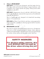
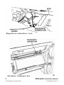
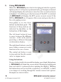
. . www.ecumate.com . . . . www.ecumate.com . . . . www.ecumate.com . . . . www.ecumate.com . . . . www.ecumate.com . . . . www.ecumate.com . . . Diagnostic and Fault code reader for the Lucas 14CUX ECU www.ecumate.com . . . www.ecumate.com . . . . www.ecumate.com . . . . www.ecumate.com . . . . www.ecumate.com . . . . www.ecumate.com . . . . www.ecumate.com . . . . www.ecumate.com . . . . www.ecumate.com . . . . www.ecumate.com . . . . www.ecumate.com . . . . www.ecumate.com . . . . www.ecumate.com . . . . www.ecumate.com . . . . www.ecumate.com . . Contents on si er V 1. What is ECUMATE?3 2.ECUMATE controls 3 3.ECUMATE screens 4 4.Connecting ECUMATE 6 5.Using ECUMATE 10 6. ECU power on reset test 12 7. Reading fault codes 14 8. Clearing fault codes 15 9. Basic status display 17 10. Throttle display 19 11. Typical throttle pot voltages 20 12. Throttle display bar graph 21 13. Fuel pump control 22 14. Fuel pump operation 23 15. Lambda display 25 16. Lambda operation 27 17. AFM values 29 18. AFM typical values 31 19. Stepper motor/idle valve control 32 20. Idle control 34 21. Idle control and stepper motor operation 37 Appendix A —Pinout of the 40-pin ECU connector 44 Appendix B — 14CUX Fault codes 46 Appendix C — Fault symptoms 48 Appendix D — Setting the base idle 50 Appendix E — Instruction manual updates 52 2 2 © ECUmate Limited 2012 ECUMATE instruction manual ECUMATE 2012/v2 1. What is ECUMATE? er V ECUMATE is an easy-to-use diagnostic unit that makes the key ECU data visible and allows the testing of engine hardware, such as the idle valve control and the fuel pump, which provide status information to the ECU. ECUMATE communicates directly with the 14CUX ECU using the five pin ‘TestBook’ connector that is present on all installations using the 14CUX ECU. This is a lightweight unit, designed to be hand-held, measuring approx. 12 x 17.5 x 3.5cm. si ECUMATE provides a cost-effective and time saving approach to diagnosing faults, in addition to allowing regular checks to monitor engine health. 2.ECUMATE controls on The controls comprise three push buttons and a 4 row x 20 character white text on blue background back-lit display, which enhances visibility in bright sunlight. The buttons are used to navigate through the various screens and provide the menu control functions. SAFETY WARNING 2 For obvious safety reasons, this unit SHOULD NOT be used by the driver when driving the car! ECUMATE instruction manual ECUMATE 2012/v2 3 © ECUmate Limited 2012 3.ECUMATE screens er V ECUMATE provides diagnostic information and test facilities through its various screens. Some information is displayed on more than one screen to facilitate ease of use. Screens include: • ECU power on reset test • Reading all ECU fault codes • Clearing fault codes without resetting the ECU • Basic status display si • water temperature • fuel temperature • throttle pot status • RPM • battery voltage • ECU status • Throttle display on • ECU comms link status • throttle pot status • throttle position as percentage, a voltage and a bar graph • Fuel pump control • fuel pump status • fuel priming operation • Lambda display lambda status lambda values ECU mapping site movement throttle pot status ECU status 4 © ECUmate Limited 2012 2 • • • • • ECUMATE instruction manual ECUMATE 2012/v2 • AFM values er V • high and low AFM voltages • mapping values • tune resistor values • map selection • Stepper motor / idle valve status • direct control of the stepper motor • valve position • Idle control road speed automatic/manual gear box status air conditioning status idle mode on/off stepper motor position on si • • • • • 2 ECUMATE instruction manual ECUMATE 2012/v2 5 © ECUmate Limited 2012 4.Connecting ECUMATE ECUMATE has two connectors: er V • A 12V DC power lead and plug which goes into the cigarette lighter socket. As soon as power is applied to the ECUMATE it will power up, ready for use. The plug itself is internally fused and has a power LED that lights up when there is power. Note: if the immobiliser is not disabled, ECUMATE will not power up. si • A communications cable which goes into the ‘TestBook’ connector socket on the ECU loom. This is a triangular shaped connector with five pins in two rows (a row of two and a row of three) and will often have a shorting connector installed. This shorting connector must be removed before connecting the ECUMATE. The TestBook connector should not be confused with the fault code reader socket which has four wires going into it — see the diagrams below. on 2 6 © ECUmate Limited 2012 ECUMATE instruction manual ECUMATE 2012/v2 Do not connect to this! This is the right one er V si To plug in the unit, first locate the TestBook connector. It is usually in the passenger foot well next to the ECU in TVRs or behind a flap under the driver’s seat in Range Rovers. The lead simply plugs in. The communications lead connector is keyed so that it can only be inserted one way. on Remember: The TestBook connector socket usually has a shorting plug fitted. Disconnect this before plugging in the ECUMATE communications lead connector. The shorting plug prevents the ECU seeing any electrical noise on the communications link as data requests or commands and subsequently causing problems. It should be replaced when ECUMATE is disconnected. 2 ECUMATE instruction manual ECUMATE 2012/v2 7 © ECUmate Limited 2012 er V Range Rover: under driver’s seat. on si 2 Alternative: inside glove box. 8 © ECUmate Limited 2012 ECUMATE instruction manual ECUMATE 2012/v2 er V TestBook connector location for TVR Griffiths and Chimaeras: Next to ECU/battery in foot well. on si 2 ECUMATE instruction manual ECUMATE 2012/v2 9 © ECUmate Limited 2012 5.Using ECUMATE er V When the ECUMATE power lead is first plugged into the cigarette lighter socket, it will power up automatically, go through an internal self test and display the software revision for a few seconds as shown in Section 2. It will then go to the first screen. If the ECU is switched off, ECUMATE will display the ECU power on reset screen. If the ECU is ECUMATE on, it bypasses this screen and goes directly to the code reading screen. Navigation is via the three buttons on the front panel. The functions of these buttons are indicated by the titles on the bottom line of the display. si The left hand button is used to move between the different screens, with each screen providing a different function or information display. on The right hand button is used to move within a screen or to retry function in the case of error. The central red button is used to stop and start the idle control valve or stepper motor. Using the buttons 2 To use a button, hold it down until the display goes blank, then release it. ECUMATE will blank the screen when it detects the button push then wait until it is released before updating the display. Holding the button down will not act like a repeat key, as with a PC, so there is no danger of scrolling through the various screens and options. Examples are shown below. 10 © ECUmate Limited 2012 ECUMATE instruction manual ECUMATE 2012/v2 er V Left hand button Right hand button Right hand button on si Right hand button 2 Centre & Right hand button ECUMATE instruction manual ECUMATE 2012/v2 11 © ECUmate Limited 2012 6. ECU power on reset test er V This checks that the ECU is working correctly. It primes the fuel pump and resets the stepper motor position when the ECU is first powered on. To run this test, connect ECUMATE to the TestBook connector and to the cigarette lighter but do not switch on the ECU. This will force ECUMATE into performing the test. After the self test screens, it will display the reset test screen. on si If the ECU is not switched on, ECUMATE will wait until the ECU is ready. Now switch on the ECU. ECUMATE will detect this and will determine the status of the fuel pump and the stepper motor and display what is happening. Typically, the fuel pump should be switched on for a couple of seconds to prime the fuel rail. Fuel pump priming will be displayed, followed by Fuel pump PRIMED. Initially, the stepper motor position should be reset to 0 and then move to a position in the range 109-140, shown as 129 in the example. 2 Failure to do either may not be catastrophic as some TVR versions of the 14CUX seem to randomly not perform this sequence. If the test is not completed successfully, try starting the engine. If it starts then the fuel pump must be switched on and ECUMATE will display Fuel pump priming. The failure to reset the stepper motor may cause problems with idle but these can be investigated further with later screens. 12 If the engine does not start but the message Fuel pump priming appears, the fuel pump is being switched on but something else is going wrong. This may be something simple as forgetting to disable an immobiliser. ECUMATE instruction manual © ECUmate Limited 2012 ECUMATE 2012/v2 on si er V If this message does not appear, go to the fuel pump control screen and turn on the pump manually. If the pump still does not start pumping, there is a problem either with the pump itself, its power feed, fuses or immobiliser or its connections. 2 ECUMATE instruction manual ECUMATE 2012/v2 13 © ECUmate Limited 2012 7. Reading fault codes er V This screen allows the fault codes stored in the ECU to be read at any time. To skip this and go to the next screen, press NEXT. si The code reading process is started by pressing RUN. This will fetch the information and display it, one fault at a time. Each fault is numbered at the top right hand corner of the screen where the total number of faults and the current fault number is shown. The faults can be stepped through by pressing NEXT. Descriptions of the fault codes are shown automatically. on When the last code is displayed, leave by pressing EXIT. If NEXT is pressed at this point, it will re-fetch the fault codes. 2 ECUMATE will fetch ALL the fault conditions that the ECU has flagged. Please note: the faults are only kept while the ECU is connected to the battery. Disconnecting the battery or the ECU itself will clear all internal faults. ECUMATE can clear the fault codes without doing this. This is described in the next section. The list of fault codes is in section 23. 14 © ECUmate Limited 2012 ECUMATE instruction manual ECUMATE 2012/v2 8. Clearing fault codes er V This menu screen allows the fault codes stored in the ECU to be cleared without having to reset or disconnect the ECU. The process is started by pressing YES. A screen will then be displayed warning what will actually happen to the fault code. si If the fault still exists, the ECU will immediately reinstate it when the fault flag is cleared. For example, if the ECU detects a fault with the throttle pot, this function will clear the fault flag but it will not cure the throttle pot fault itself. The next time the fault codes are read, the fault will still be flagged if the fault still exists. This is the correct operation of the ECUMATE, not an ECUMATE fault. on To start the operation, press CONT. If the ECU is not powered up or the comms cable is disconnected, E C U Connection error will be displayed. ECUMATE instruction manual ECUMATE 2012/v2 2 ECU MATE will display status information on the fault clearance process and will indicate if an error occurred. The process can be repeated by pressing R E T R Y in either case. Pressing NEXT will go to the next screen. 15 © ECUmate Limited 2012 ECUMATE does not fix faults — it only reports them so they can be fixed and a fix confirmed! on si er V Once a fix has been attempted, clear the fault codes using this function and read them again. See Section 7. If the fault has been cured, the fault code will not appear. If the fault code still appears, the fix has not been successful. 2 16 © ECUmate Limited 2012 ECUMATE instruction manual ECUMATE 2012/v2 9. Basic status display er V This screen shows the basic engine parameters and can be used as a first level check that the engine is running correctly. Water Displays the water temperature (in degrees C) that the ECU sees from the temperature sensor. This can be can be compared with the car’s dashboard temperature gauge or other temperature readings to check that the ECU is getting accurate information. on Fuel si If the value is lower than expected, the ECU will cause the engine to run rich as it will think the engine is cold. If it is higher, the engine will run lean and may not idle well when cold but it will run better when warm. Displays the fuel temperature (in degrees C) that the ECU sees from the temperature sensor. This is used to determine the risk of fuel vaporisation. If defective, this can lead to starting difficulties when the engine is hot. Typical values are from ambient to around 50C. TPOT 2 This has a value between 0 and 100% with 0 being closed and 100% fully open. A value of 11% that doesn’t change when the throttle is moved indicates that there is a fault with the throttle pot and the ECU is using a default ‘limp home’ mode. This should also generate the associated fault code. This will happen if the throttle pot is unplugged or the connections go open circuit. The engine will still run but not very well. ECUMATE instruction manual ECUMATE 2012/v2 17 © ECUmate Limited 2012 RPM er V Indicates if the ECU is seeing the coil pulses from the ignition system and displays the current engine RPM. If it is 0, no pulses are recognised by the ECU and it will not fire the injectors. If it is above 0, the engine is running. The signal is taken from the negative 12V coil connection via a 6.8 kOhm resister that is built into the loom. This should not be confused with the tune resistor. Batt Displays battery voltage as seen by the ECU. This reading can be slightly less than the voltage measured at the battery terminals because of the resistance of the wiring. The reading will drop to around 9 volts when the starter is used to turn the engine over. The ECU and ECUMATE will continue to work at these lower voltages. si ECU: on Displays OK if the communication link to the ECU is functioning correctly and the data snap shot is consistent. If there is a problem, ERROR will be shown instead. This can be caused by the ECU being switched off or disconnected. 2 18 © ECUmate Limited 2012 ECUMATE instruction manual ECUMATE 2012/v2 10. Throttle display er V This reports the throttle voltage as seen by the ECU and is used to check throttle operation and to help set it up. The value is read from the ECU several times a second to provide real time values. .57V ECU: si The voltage on the left is the actual voltage that the ECU sees from the throttle pot. This will vary from 0 to 5 volts but the throttle pot should be set up to provide a minimum and maximum voltage. These voltage values are used by the ECU to work out when the driver wants to accelerate and additional fuelling is needed. 11% on This is the status of the ECU comms link. OK indicates that the ECU is operational and communicating. If the link fails, OK changes to ERROR. LIMP HOME DETECTED 2 This is how much the throttle is open has a value of 0% to 100% with 0% being closed and 100% fully open. This value is linear until it gets towards 0% i.e. below the throttle minimum position. When this happens, the value can suddenly change when the ECU detects, assumes that there is a fault and substitutes a default value of 11%. This indicates that there is a fault with the throttle pot and the ECU is using a default ‘limp home’ mode. This will be shown instead of a bar graph (see Section 12) when the ECU detects a fault and uses a default value. ECUMATE instruction manual ECUMATE 2012/v2 19 © ECUmate Limited 2012 11. Typical throttle pot voltages on si er V The throttle pot voltage should be in the range 0.3 to 0.5V when the throttle is closed. This corresponds to a percentage value of about 3 to 5%. On full throttle the voltage will be around 4.5 to 5 volts. The ECU can cope with slight variances in the voltage but it is important for correct operation that the throttle pot is adjusted so that it meets the minimum values. If this is not done, the throttle position may exceed the idle off threshold so that the idle mode is not enabled when the throttle is closed. This can be checked by using the idle control screen and moving the throttle, as described in section 12. 2 20 © ECUmate Limited 2012 ECUMATE instruction manual ECUMATE 2012/v2 12. Throttle display bar graph er V The bar graph indicates whether the current throttle voltage value is greater, less or unchanged, compared with the previous value. This is done by the bar graph character changing as follows: >>> Increasing value <<< Decreasing value === Unchanged si The bar graph can be used to check for noise caused by dirty or corroded pot track, corroded connections, etc. by simply slowly pressing the throttle. As it moves, the bar graph should show >>> and === when it reaches its limit. on If there is any noise, the bar graph will jump and may change symbols. Whilst not totally foolproof in detecting noisy throttle pots, it gives a very good indication of a problem. 2 ECUMATE instruction manual ECUMATE 2012/v2 21 © ECUmate Limited 2012 13. Fuel pump control er V This screen shows the fuel pump status and allows the user to override the ECU and switch the fuel pump On or Off. This is done by pressing the right hand button, which toggles between TURN OFF and TURN ON. si When the fuel pump is switched on, the injector symbol on the top line will start ‘spraying’. The ECU normally switches the pump on for a second or two when it is first switched on to prime the fuel system and will only switch the pump on when it receives a crank signal from the coil, indicating that the engine is turning over. on The fuel pump usually goes through an immobiliser and if this is faulty or active, the fuel pump supply circuit will usually not operate. Please note: if the engine is not running, the ECU will switch the pump off for safety reasons. If the fuel pump is switched on using ECUMATE when the engine is not running, the ECU will detect this and immediately switch it off again. ECUMATE detects this and will switch it back on. This means that there may be a momentary interruption on the signal from the ECU. This is normal. This function should be used with care. If the engine is running, switching the fuel pump off will STOP THE ENGINE! 2 22 © ECUmate Limited 2012 ECUMATE instruction manual ECUMATE 2012/v2 14. Fuel pump operation er V The fuel pump is controlled by the ECU. It will send a signal out on connector pin 16 that energises the fuel pump via relays, fuses and the car’s immobiliser. The fuel pump is switched on when either of two events occur: • When the ECU is first powered on, the fuel pump is switched on for a couple of seconds to prime the fuel rail and pressurise the system. si • When the ECU detects that the engine is being cranked, it will switch on the fuel pump. The ECU knows when the engine is turned over as it receives the ignition coil pulses. It counts these pulses to work out when the engine is cranked and to determine the RPM when running. This signal is critical. If it is not seen or it is incorrect, the ECU will not fire the injectors or even start the fuel pump! on At all other times, the ECU will switch the pump off for safety so that fuel is not continually pumped when it is not needed. This means that when ECUMATE turns the pump on, the ECU will turn it off again and cause a little interruption. ECUMATE will turn the pump back on immediately if this happens. 2 If the fuel pump priming does not occur, it may not be a real fault. Some ECUs — notably those used in TVRs — do not always prime the pump on power up. Instead, the pump is energised when the engine is cranked. The engine will still run but it may take a little longer to fire up. It is important to perform further checks to make sure that the car does not have this ECU type. This can be done by starting the car while in the ECU power on reset test screen. If it runs, the ECU will switch on the fuel pump and ECUMATE will display fuel pump priming, indicating that the fuel pump is working. If the engine does not start and fuel pump priming does not appear, the problem is likely to be associated with the input signal ECUMATE instruction manual ECUMATE 2012/v2 23 © ECUmate Limited 2012 on si er V from the coil and the ignition system. If there are no sparks and hence no ignition, the ECU will not receive any indication that the engine is turning over. As a result, it will sit and wait and not do anything. If the ignition system is working and there are sparks at the spark plug, but still no fuel pump priming message, the problem is likely to be the connection between the coil and the ECU itself. 2 24 © ECUmate Limited 2012 ECUMATE instruction manual ECUMATE 2012/v2 15. Lambda display er V This screen shows the lambda, idle and throttle pot status. The throttle pot value is shown as a percentage. The 14CUX ECU uses two lambda sensors, known as Lambda A and Lambda B. Their values are displayed along with text describing the mixture status. LamA, LamB si These can be LEAN, RICH or OK. The sensors are narrow band and act as a switch to indicate either a rich or lean mixture. As a result, the ECU oscillates between the two conditions so that on average, the mixture is correct. This switching happens about once a second. on If the values stay at 0, the lambda has reached a LEAN clamp and this may indicate an error. Similarly, if it reaches and stays on 255, it has reached a RICH clamp. This can give some indication of how the lambda has failed, if a lambda fault is given. Along side each of the values is a symbol that indicates the sensor status. This can either be _ or ■ for low and high respectively. If the value is stationary, X is shown indicating that the value is not oscillating or that the ECU is running in open loop mode. TPOT 2 The throttle position is shown with this screen because lambda control is typically only operational when the throttle is relatively closed i.e. not fully open. Faults with this component can cause problems with lambda operation. The throttle value is shown as a percentage which represents how much the throttle is open and has a value of 0% to 100% with 0% being closed and 100% fully open. This value is linear until it gets towards 0% i.e. below the throttle minimum position. When this ECUMATE instruction manual ECUMATE 2012/v2 25 © ECUmate Limited 2012 er V happens, the value can suddenly change when the ECU detects, assumes that there is a fault and substitutes a default value of 11%. This indicates that there is a fault with the throttle pot and the ECU is using a default ‘limp home’ mode. This should also generate the associated fault code. Idle This is a idle mode status and is provided for use when trying to establish what mode the ECU is operating in. on si 2 26 © ECUmate Limited 2012 ECUMATE instruction manual ECUMATE 2012/v2 16. Lambda operation The Lambda operation is again controlled by several inputs: er V • Map selection via the tune resistor This is the colour coded resistor that plugs into the loom. The value selects which of the six internal maps the ECU will use. Some of these maps are designed to run with no cats and, when selected, the lambda operation is disabled. • Sensor temperature The lambda sensors do take some time to warm up. During this warm up time the lambda values are ignored. si • Engine RPM on Lambda control is only operational from idle to about 3-4,000 rpm. In this range, the ECU operates in closed loop mode, where the lambda value is used to trim the mapping so that the emissions are maintained within correct values. When the RPM goes outside this range, the ECU switches to open loop operation where the lambdas are effectively ignored. • Throttle movement When the throttle is moved quickly, lambda control can be temporarily removed to enable extra fuel to be added to improve the engine pick up and response. 2 When the ECU is running in closed loop mode, the lambda values will oscillate from low to high about every second. A low value indicates lean and a high value indicates a rich mixture. When working correctly, ECUMATE reports an OK status and indicates the oscillation by displaying a symbol next to the value. This can either be _ or ■ for low and high respectively. If the value is stationary, X is shown, indicating that the value is not oscillating or that the ECU is running in an open loop mode. ECUMATE instruction manual ECUMATE 2012/v2 27 © ECUmate Limited 2012 Raising the revs over 4,000 rpm will change an oscillating lambda value to a fixed one. As the revs drop below the threshold, the values should start changing. er V As stated earlier, lambda operation can be switched off with the map selection. It is worth checking that the ECU is running the right tune resistor and selecting the correct map before assuming that a non-oscillating lambda value indicates a fault. The limp home mode map that is selected when there is no resistor or it has gone open circuit assumes that the vehicle has catalytic converters fitted and will even simulate lambda operation if they are not connected or fitted! on si It is not uncommon for the lambdas to oscillate at different speeds and ranges. This may indicate that a lambda sensor is getting tired and not responding as fast. This is not necessarily a fault, as the ECU will continue to operate, but more of an advance warning that the sensors may need replacing in the future. The tired sensor is usually the one that is oscillating the slowest and whose range changes are the smallest. 2 28 © ECUmate Limited 2012 ECUMATE instruction manual ECUMATE 2012/v2 17. AFM values er V This information screen displays four AFM parameters, the tune resistor value and associated map selection. The AFM-Lo and AFM-Hi parameters show the low and high AFM voltages as seen by the ECU. The two parameters should track each other. If they don’t, it indicates a possible fault. This voltage should vary from 0 to 5 volts. on si Mapping data is provided for a ‘confidence check’ that the ECU is getting information from the AFM and is using that information correctly. It reflects which mapping sites the ECU is using. The values are effectively meaningless but the fact that they are changing indicates that the ECU is adjusting the mapping to cope with the engine RPM and AFM values. The 0 101 values shown in the example screen are typical and occur when the ignition is switched on but with the engine not running. They will change when the engine runs and will move when the throttle is opened. If the AFM-Lo and AFM-Hi values do not change with RPM or throttle position, this indicates that there is a problem with the AFM, its electrical connections or even the linking hose to the plenum i.e. anything that will stop the air flow through the AFM or allow air to bypass it and not be measured. 2 If the MAPPING values do not change with RPM, there is a likely to be a major fault. The first will change with the AFM value and the second with the engine revs. These are normally linked because as the throttle voltage increase, the air flow into the engine will increase and so both values will move. The important point is for them to increase together. If they don’t, there is an issue with either the throttle pot or the AFM. ECUMATE instruction manual ECUMATE 2012/v2 29 © ECUmate Limited 2012 The ECU will flag a fault code if the AFM value is high while the throttle position is low and vice versa. So if there are no other faults reported, this indicates that the problem may be with the ECU itself. er V The AFM values only become valid when the engine is running. If the engine is stopped, the values are meaningless. The tuning resistor colour and corresponding map selection is shown in the table. When the engine is started, the ECU measures the resistance of the tune resistor and uses this to select which of the six internal maps to use. Five maps are allocated to a particular resistance value and a default sixth for use if no resistor is detected. This is a limp home mode where the ECU will keep the engine running — albeit not at its best. si Each resistor is allocated a colour and value by the changing the tune resistor for a different colour, the map can be changed. If the wrong map is selected, the engine may not run correctly or if catalytic converters are fitted, they may be destroyed. It is essential that the correct tune resistor is used and that it is recognised correctly. on Colour Value Catalyst Common Application Red 180Ω No Australian 3.9 Green 470Ω No Europe & UK 3.9 (or 3.5 Disco) Yellow 910Ω No Gulf States 3.9, or Europe & UK 4.2 Blue 1.8kΩ Yes Gulf States 3.9, or Europe & UK 4.2 White 3.9kΩ Yes Europe & UK 3.9 (or 3.5 Disco) N/A O/C Yes Limp home mode Note: The resistances above are approximate The tune resistors commonly used in the UK are Green for vehicles with no catalytic converters and White for vehicles with them. 2 30 © ECUmate Limited 2012 ECUMATE instruction manual ECUMATE 2012/v2 18. AFM typical values er V Typical values for the AFM voltage are about 1.7 volts on tick over, rising to a maximum of 5 volts on full throttle with a big capacity engine, such as a TVR 5 litre engine. Whilst the AFM will supply the ECU with a voltage of around 0.3 to 0.7 volts when the engine is not running, the ECU effectively ignores it and ECUMATE will report a static default value in the AFM screen. on si 2 ECUMATE instruction manual ECUMATE 2012/v2 31 © ECUmate Limited 2012 19. Stepper motor/idle valve control er V This information screen displays the stepper motor/idle control valve position as seen by the ECU. The function buttons allow ECUMATE to control the idle valve by either retracting or extending the valve tip position. This allows the valve and its wiring to be checked for correct operation. Retracting allows more air to bypass the throttle and the idle speed should increase. Extending the stepper motor will restrict the air and the idle speed should decrease to the point where the engine may stall. on si The centre red button will Move and Stop the valve and the right hand button will set the direction: either Extend or Retract. Position(ECU): 2 This displays the current position of the valve as seen by the ECU. It will change when the ECU starts to use the valve to control the idle speed and will vary from 0 to 255. The ECU will extend the valve when it is first powered up to reset its position. This forces the valve against the housing and then it will move it back into a mid position as indicated by a typical value of 109. This final value can be map dependent though. There is no feedback from the valve to the ECU and it has to reset the position so that it knows exactly where it is. Typically, this is done when the ECU is first powered up. ‘Typically’ is used deliberately as some TVR versions of the ECU do not do this 100% of the time. 32 © ECUmate Limited 2012 ECUMATE instruction manual ECUMATE 2012/v2 er V If the valve is removed from the plenum, the plunger can be extended so far that it is unscrewed and will need to be screwed back. Care needs to be taken when testing the stepper in this way. The stepper motor is also constantly powered and as a result will become warm to touch. Again, this is quite normal. The constant powering locks the plunger in position so that it cannot be moved except by sending it the appropriate control signals. si When controlling the valve via ECUMATE, the position shown on the screen is not updated. It only reflects any positional change done by the ECU. The ECU may also try to take control if the valve is moved to an extreme. on Several factors can affect the stepper motor position. Changes in the gear box and air conditioning status will cause a small change in the position. The ECU will go into the idle mode when it detects through its road speed sensor that the car is stationary. If this signal is not present, the car may fail to idle correctly as the ECU thinks the car is stationary when it is in fact moving, or vice versa. Some faults (e.g. a disconnected water temperature sensor), may prevent the stepper motor from resetting on power up and give the impression that the stepper motor is faulty. If this is suspected, ECUMATE can be used to move the stepper motor directly to confirm that it is still working. The next screen displays more information on this. 2 ECUMATE instruction manual ECUMATE 2012/v2 33 © ECUmate Limited 2012 20. Idle control er V This information screen displays information on the idle control/status and can be used to diagnose poor or high idling. The 14CUX ECU will only go into full idle mode when it detects the car is stationary and the throttle position is below the idle threshold point. ROAD on si This signal is used by the ECU to determine whether the car is stationary or moving. The information is shown in two ways: the actual value and a text interpretation of what the status is e.g. stop and 0. Its primary use is to tell the ECU when to switch into idle mode but in some vehicles it is also used to trigger an upper speed limit. This limit is usually restricted to 4x4s and is usually removed in TVRs and other sports cars. However, if an ECU is replaced, an upper speed limit may be inadvertently enabled. The values are displayed as both a status and as an actual value. This signal will change with the road speed and is taken directly from the built in speed sensor fitted to the LT77 gearbox. On T5 equipped TVRs, such as the Griffith 500, this signal is supplied by a ‘conversion’ box that takes the road speed sensor signal and generates an additional version for the ECU. This is an ‘all or nothing’ type signal that bears no relation to the actual road speed. As long as the car is moving, the signal is constantly generated. It does not change as the car slows down. 34 2 BOX This signal tells the ECU whether the car is in park or neutral (P/N) or drive (-D-). This is normally changed by a micro switch on the automatic gear box. The ECU recognises the gearbox status by measuring the voltage between the input pin and ground. There ECUMATE instruction manual © ECUmate Limited 2012 ECUMATE 2012/v2 A/C si er V is normally a resistor connected between these two pins and by changing this, the ECU can discriminate between values and hence gearbox status. As a result, the values change a little and are not simply 0 or 255. Instead, the ‘0’ value can actually vary between 0 and 50 and the ‘255’ value from 230 to 255. With sports cars like TVRs, it can display an intermediate value of about 128 — indicated by ???. With some Marcos cars, this signal is left open with no modifications to the software and this can lead to a fault code being flagged up. The cure is to connect a 510 ohm resistor between the signal and ground to force it into the P/N mode. The fault can also happen if the engine is started while in Drive mode as the ECU interprets this as being a fault. The starter should be disabled when in this mode. With the TVR version, this does not cause a fault — but with standard ECUs it can. Changes in the status will cause the ECU to adjust the revs via the stepper motor position. IDL on This signal tells the ECU whether the air conditioning is switched on or not. Like the BOX signal, any change will cause the ECU to change the RPM to cope with the change in engine load. If the air conditioning is switched on, the engine RPM will increase. If it is switched off, they will fall. On some cars, including TVRs, this signal may be inactive or not connected to the ECU. 2 This signal indicates that the ECU is an idle mode and should only state ON when the car is stationary. It should reflect the ROAD signal in that it will be on when ROAD is 0 and off when it is greater than 0. If not, this indicates a fault with the road speed. If it is permanently zero then the idle mode will be permanently on and the car may stall when lifting off at a junction. If the road speed is greater than zero, then idle mode will be permanently off and idle speed may stay high. ECUMATE instruction manual ECUMATE 2012/v2 35 © ECUmate Limited 2012 POS er V This is the stepper motor position as seen by the ECU. It will change as the ECU uses the stepper motor to control the engine RPM during the idle mode or if additional engine loads are placed on it or when the throttle is lifted during a gear change. This indicates that the stepper motor is actually being used when the ECU enters idle mode or moves in response to changes in the BOX or A/C signal. Increasing electrical load, such as engine fans, may also cause it to change, especially when the load is removed. ECU: OK. This is the status of the communications link between the ECU and ECUMATE. If a problem is detected, the status will change to ERROR. on si 2 36 © ECUmate Limited 2012 ECUMATE instruction manual ECUMATE 2012/v2 21. Idle control and stepper motor operation er V Idle control and stepper operation are closely connected. The stepper motor is only used when the ECU is in idle mode and, as a result, many so-called ‘stepper motor faults’ are not caused by a defective part but by the ECU being in the wrong mode. Idle control is only entered when the throttle pot is set to below a threshold and the car is stationary or moving below a idle speed threshold. This threshold speed is about 3 mph. If a road speed signal is constantly supplied to the ECU, the ECU will not enter idle mode, the stepper motor valve will not extend, so idle remains high and seems to be stuck. si If no road speed signal is present, even when the car is moving, idle mode will only be entered when the throttle is lifted and this can result in stalling as the ECU tries to bring down the revs when it shouldn’t, e.g. lifting off the throttle when coming to a halt. As a result, intermittent road speed signals will cause idling problems. on On entering idle mode, the ECU brings down the revs by extending the stepper to quickly restrict the air flow. Once this has been done, it does nothing else. If ECUMATE is used to reposition the stepper during idle, the idle speed will fall and rise accordingly but the ECU will not intervene to correct the changes. It assumes that once it has established idle, that is it. If the mixture or ignition is faulty so that the idle is not smooth, the ECU will not try to adjust the stepper to help smooth the idle. 2 Whilst it is important to keep the stepper motor clean and to have the base idle set correctly, many idling issues are caused by these other signals — which is why they have been brought together on this screen. The stepper motor position is not fed back to the ECU — the ECU makes an assumption about where it is, based on the number of pulses it supplies. The power on reset sequence allows the ECU to move ECUMATE instruction manual ECUMATE 2012/v2 37 © ECUmate Limited 2012 the stepper position to a known point. After that, it relies on pulse counting, assuming that all moves are done correctly. er V If the stepper motor is sticky, this will not be the case and it will throw out the position. If the position is not reset on power up, this can have the same affect. The end result is that the ECU will move the stepper motor according to its programming, thinking that it has actually done what has been expected. The reality is that the stepper motor will be in the wrong position and cause less than ideal idling. What happens during idle? on si During normal driving with the car moving and the throttle above the idle threshold (typically 6%) the ECU does not operate any idle control. The stepper motor should be retracted and it will typically retract beyond the idle position, allowing a little more air into the plenum and effectively maintaining a higher than normal idle. When the driver lifts off and the throttle pot moves to its minimum position, this will still not put the ECU into idle mode as the ECU knows the car is still moving. When the car stops, the road speed signal will also stop and about 2-3 seconds later the ECU will enter idle mode and start to reduce the engine revs. At this point, the stepper motor is retracted, so a lot of air can flow and this will keep the idle high. The ECU reduces the idle speed by extending the stepper valve. This is done initially with a couple of quick bursts. If this does not bring the idle speed down then the ECU will continue to extend the stepper by a couple of positions about every 1-2 seconds. It will continue to do this even if the stepper is fully extended and cannot move any more. If the idle speed comes down to the preset value of around 750-800 rpm, the ECU will stop adjusting the stepper. 2 When the throttle is pressed, the ECU will retract the stepper slowly - a couple of positions per second - until the stepper is retracted and effectively ready for the next time the car comes to a halt. Blipping the throttle when the car is stationary will cause the ECU to come out of idle mode and start slowly retracting the stepper motor until it is either retracted or the throttle is released. Because of the short 38 © ECUmate Limited 2012 ECUMATE instruction manual ECUMATE 2012/v2 er V duration of the blip, the stepper is very close to its idle setting when the ECU moves back into idle mode and it doesn’t take very long to move back. As a result, the engine seems to come back to idle instantly, although the reality is it may take a couple of seconds. In these circumstances, a slight hovering above idle can often be noticed. The same process happens when the car starts moving, although now the fact that the car is moving means that the ECU will stay out of idle control. When the throttle is released, the ECU will not attempt to bring down the revs because the car is moving. Other idle factors on si This means that the revs are kept higher during a gear change to help prevent rear wheel lock up and that the ECU will only go down to the low idle speed if the throttle is below the idle threshold and there is no road speed signal. If there is a fault (i.e. no speed signal), the ECU will try to enforce the low speed idle as soon as the throttle is lifted and while the engine is under load, because the car is still moving. In these circumstances, this is why the car may stall. There are some additional factors here. The rate at which the ECU moves the stepper motor is dependent on the value of the throttle pot. If it is around .35v, the ECU will move quickly in large bursts and then trim slowly with a new value every 1.5-2 seconds. If it is below this value (e.g around .2V), the ECU will move the stepper motor every 4 seconds and a few position locations at a time. As a result, it can take a long time for the idle to come down. 2 This mechanism is further complicated by the fact that the amount of air that the idle valve can control is defined by the position of the bleed screw. The amount of air can be adjusted using a procedure called ‘setting the base idle’. This is described in the appendix. If this is not set up correctly, the ECU’s estimated idle position does not give the normal idle RPM and the ECU will need to move the stepper motor more. In this case, it will take longer to reduce the ECUMATE instruction manual ECUMATE 2012/v2 39 © ECUmate Limited 2012 er V air flow enough to lower the idle to the correct RPM. So, if the ECU goes into this mode, the idle will remain high for quite some time before dropping down. If this combines with the low throttle voltage (described above), it can take many seconds for the idle to come down. This is often thought to be a stepper motor fault but is in fact normal operation by the ECU — it is simply responding to the incorrectly set up throttle pot and base idle. Air leaks The description so far has assumed that there are no air leaks allowing air to bypass the air flow meter and enter the plenum. If this happens, the mixture will be leaned out and the ECU may find itself in difficulties because it cannot bring the idle down by moving the stepper motor. si Idle road speed threshold on This is another key factor because it is a trigger point for the ECU to go into idle mode. It is typically set to a value of 3 mph. However, it is important to understand that the actual value used by the ECU is a pulse count coming from a sensor that counts shaft revolutions in the gearbox, or from the prop shaft or drive shaft. As a result, the actual value in mph may vary, especially when the engine is installed in a non Land Rover car. 2 TVR also complicated things by changing to a T5 gearbox and different speed sensor type that could no longer drive the ECU directly. To solve this, they built a speedo conversion circuit which takes in signals from the speed sensor and outputs either a zero or 30 mph equivalent signal to the ECU. This means that the ECU thinks the car is doing either 0 or 30 mph. The change is very abrupt and it takes about 2-3 seconds for the ECU to see the zero signal. The problem here is that the unit only sends the signal when the car is stationary. Even if the car is only moving at 1-2 mph, the ECU thinks it is moving at 30 mph. Again, this can result in a high idle being maintained when the driver thinks that the engine should be running 40 © ECUmate Limited 2012 ECUMATE instruction manual ECUMATE 2012/v2 Valve Shut Low idle High idle Valve Open er V >180 ~112 3 0 ~92 1 2 Throttle released. Road speed > threshold Idle mode OFF Throttle released. Road speed < > threshold Idle mode ON ECU starts moving stepper until low idle established si Throttle released. Road speed < > threshold Idle mode ON ECU stops moving stepper Low idle established Normal operation with good base idle Valve Shut Actual Idle >180 High idle ~112 2 LONG DELAY 0 ~92 1 3 Valve Open on point VERY Low idle Throttle released. Road speed > threshold Idle mode OFF Throttle released. Road speed < > threshol d Idle mode ON ECU stops moving stepper Low idle established 2 Throttle released. Road speed < > threshold Idle mode ON ECU starts moving stepper until low idle established Normal operation with bad base idle ECUMATE instruction manual ECUMATE 2012/v2 41 © ECUmate Limited 2012 er V at its low idle. The ECU will not start reducing the idle speed until the car is stationary. Add to this a couple of seconds delay and the potential delay due to a badly set base idle, and the car can exhibit a persistent ‘high idle fault’. This ‘fault’ is usually blamed on the stepper motor and so on — but it is ‘normal’ behaviour, given the fact that the ECU is coping with unexpected speed signals. In the Land Rover, the ECU starts reducing the idle speed when it goes below the threshold so that when the car eventually stops, the low idle is already there. I am currently developing a replacement unit for the TVR T5 gear box that generates the correct speed profile, allowing the speedo to be recalibrated and effectively allows the speed threshold to be adjusted to come in later, if needed. si Solving high idle problems 1. Set the correct base idle 2. Ensure the stepper motor is clean and reset if necessary on 3. Replace the TVR speedo unit to correct the ECU speedo signal. During ECUMATE pre-production testing, it was found that some TVRs exhibit a random stepper motor reset on power up, which may explain why they can suffer with idling issues because the initial starting position is inaccurate. In these cases, the reset is only performed randomly, which leads to random idling problems. It is possible to use ECUMATE to reset the position by moving the stepper directly to correct the problem. 2 42 © ECUmate Limited 2012 ECUMATE instruction manual ECUMATE 2012/v2 si er V This page is intentionally blank. on 2 ECUMATE instruction manual ECUMATE 2012/v2 43 © ECUmate Limited 2012 Appendix A —Pinout of the 40-pin ECU connector Color Red/green Brown/orange Yellow Black Gray/black Yellow (or yellow/ pink) Name Air bypass valve MAF and main relay Throttle position sensor Ground Tune resistor er V Pin 1 2 3 4 5 6 Speed transducer Green/blue Coolant temperature sensor 8 Purple/yellow Heated front screen 9 White/light green Diagnostic serial port 10 Black/yellow or red 11 Yellow/white 12 13 14 Blue/red Yellow/blue Black EFI warning light Even (right) bank injectors Main relay Odd (left) bank injectors Ground 15 Brown Ignition and main relay 16 Blue/purple Fuel pump relay 17 Gray/yellow Purge control valve 18 White/pink Diagnostic serial port 20 21 31 Output Output to main relay coil Output Input (+12VDC always applied) Output to fuel pump relay coil Output Input from 5-pin TTS connector Input (+12VDC when ignition on) Swings 0.29 to 5.00 VDC White/gray or white/ green Red Yellow/black to yellow/green Blue/red Unk Unk Red/black Green/white Black/gray Blue/gray Orange Pink Black/green or black/ yellow 32 Gray/white 33 Black/gray 44 © ECUmate Limited 2012 Fuel pump and inertia switch Throttle potentiometer Air conditioner compressor load MAF sensor Left lambda sensor Right lambda sensor MAF and ? Air bypass valve Ground Air bypass valve Air bypass valve Fault display data Diagnostic plug Input Blue shielded Blue shielded ? (Ground reference?) 48-58 ohms to pin 1 48-58 ohms to pin 29 48-58 ohms to pin 28 Output to main connector 2 22 23 24 25 26 27 28 29 30 Input from main connector Output to 5-pin TTS connector Output to main connector on 19 To brown connector si 7 Description/Notes 48-58 ohms to pin 26 Input (+12VDC) 5k ohm to pin 25 O2 sensor heater return No wire in NAS vehicles To main conn (0-12V six times per revolution) Fuel temperature thermistor Heater/air conditioner cable Input Input from gray connector - ECUMATE instruction manual ECUMATE 2012/v2 34 Orange/black Transmission neutral switch 35 Blue/green MAF sensor Black/green Condenser fan timer 37 38 (N/a) Brown/pink White/black or white/ blue Black (no connection) Fault display data Engine speed Output to main connector Ground - er V 36 Input from main connector 0.3 to 0.6 VDC with ignition on Tall green unit (AMR 3678) Output to main connector 39 40 on si 2 If you are unsure of which in is 40, check its continuity to ground. ECUMATE instruction manual ECUMATE 2012/v2 45 © ECUmate Limited 2012 Appendix B — 14CUX Fault codes 14CUX ECU fault codes Code Meaning Comments Live feed to ECU has been interrupted Normal if ECU has been disconnected to clear old fault codes. Code 02 will clear if ignition turned off for 30 seconds then on again. 03 Stored data corrupted since last trip No useful information available. Test drive and try again. 12 Air flow meter out of range Possible air leak or wiring fault. 14 Coolant thermistor out of range Faulty sensor or wiring. 15 Fuel thermistor out of range Faulty sensor or wiring. 17 Throttle sensor out of range Sensor needs adjustment or is faulty or has wiring fault. This can cause low speed misfires 18 Throttle sensor output too high when air flow low Large air leak between throttle butterfly and A/F meter or faulty throttle sensor or A/F meter. 19 Throttle sensor output too low when air flow high Faulty A/F meter or throttle sensor. 21 Tune resistor out of range Check tune resistor resistance. 23 Low fuel pressure Blocked fuel filter or faulty pump or pressure regulator. Valid for cat cars only. Misfire at full load Faulty plugs, leads, electronic ignition unit, distributor or coil, low fuel pressure or valve or head gasket leak. Valid for cat cars only. Essentially the lambda sensors have detected an emission fault and this can be caused by almost anything within the engine's ignition and injection system. Further information can be obtained by checking for a second code. on 25 si er V 02 If this is 40 or 50 it will indicate which side of the engine the fault is. Be aware though that even this can be a bit misleading if one of the Lambda sensors is not functioning correctly. 26 Very lean mixture This indicates a very lean mixture, or a misfire. Possible causes are a faulty low or out of range lambda sensor or an ignition fault causing a misfire. This code is used on the JAGUAR version of the 14CUX ECU and is generally not listed under the Range Rover fault codes. Air leak 29 Checksum error The ECU has failed its internal self test. If detected all other faults are unreliable and must be ignored. It may be worth resetting the ECU by disconnecting it, then reconnect it and repeat test as this fault can be caused by a faulty connection. © ECUmate Limited 2012 2 46 28 Check for air leaks in the following areas: * Hose, air flow meter to plenum * Breather system hoses to plenum * Brake servo hose * Vacuum reservoir hose (fresh air solenoid) * Distributor vacuum advance * Hose, purge valve to plenum * Injector seals * Any of the joints and junctions. ECUMATE instruction manual ECUMATE 2012/v2 14CUX ECU fault codes (cont) Code Meaning Comments Checksum error 34 Fuelling fault in nearside injector bank Injector or Lambda sensor wiring fault, faulty injectors, air leak at injector seals or inlet manifold, blocked injectors. Valid for cat cars only. 36 Fuelling fault in offside injector bank As above but for cylinders 2-4-6-8 only. Valid for cat cars only. 40 Misfire on nearside bank A misfire has occurred for cylinders 1-3-5-7 only. Valid for cat cars only. See fault code 25 for more details. 44 Faulty or lead-poisoned sensor or sensor wiring fault. Valid for cat Nearside Lambda sensor out cars only. If both code 44 and 45 appear then the likely culprit is of range the heater supply to both Lambda sensors. 45 Offside Lambda sensor out of range As above. Valid for cat cars only. If both code 44 and 45 appear then the likely culprit is the heater supply to both Lambda sensors. 48 Stepper motor fully open above 500 rpm or fully closed above 750 rpm Sticking stepper valve, incorrect base idle speed adjustment, air leak on non-cat cars, incorrect stepper motor adjustment, incorrect throttle butterfly adjustment, rough running because of fuel or ignition or mechanical faults. A faulty road speed input can also cause this problem. 50 Misfire on offside bank A misfire has occurred for cylinders 2-4-6-8 only. Valid for cat cars only. See fault code 25 for more details. 58 ECU unable to distinguish between faults 23 and 28 Fault occurred for insufficient time for ECU to diagnose. 59 Fuel thermistor out of range Fuel thermistor fault. Be aware that in some documentation code 59 is described as the same for 58! 68 Road speed sensor output too low at medium rpm and high air flow Possible sensor or wiring fault (may also cause wrong speedometer readings on electrical speedometer cars but don't rely on this!). Valid for cat cars only. 69 Faulty gear selector switch Applicable to Range Rovers & Land Rovers. Power-up check There are two interpretations for this: the first is that it is not a fault but is sometimes shown on power up. This is valid for non-cat cars. With cat cars, it is also used to show that there is a purge valve fault with the carbon canister system. on ECUMATE instruction manual ECUMATE 2012/v2 2 88 si er V 29 The ECU has failed its internal self test. If detected all other faults are unreliable and must be ignored. It may be worth resetting the ECU by disconnecting it, then reconnect it and repeat test as this fault can be caused by a faulty connection. 47 © ECUmate Limited 2012 Appendix C — Fault symptoms Cold start problems • High reading temperature sensor er V • Stepper motor not resetting correctly • Base idle incorrect Bad idling • Road speed signal problem (on or off) • Sticky stepper motor valve • Stepper motor position lost by ECU or not reset • Base idle not set correctly si • Ignition problems • Unexpected engine load changes Bad running Black smoke Lean mixture • Low fuel pressure • Stuck injectors on • Fuel and water temperature plugs swapped round. • Incorrect air flow meter values • High reading temperature sensor • Ignition related misfires 48 © ECUmate Limited 2012 2 • Lambda sensor fault (reading or stuck at rich) ECUMATE instruction manual ECUMATE 2012/v2 • Incorrect values from throttle pot Rich mixture/excessive fuel consumption er V • High fuel pressure • Stuck injectors • Incorrect air flow meter values • Lambda sensor fault (reading or stuck at lean) • Low reading temperature sensor • Excessive high fuel temperature reading (>60C) • Incorrect values from throttle pot on si 2 ECUMATE instruction manual ECUMATE 2012/v2 49 © ECUmate Limited 2012 Appendix D — Setting the base idle on si er V 2 50 © ECUmate Limited 2012 ECUMATE instruction manual ECUMATE 2012/v2 on si er V 2 ECUMATE instruction manual ECUMATE 2012/v2 51 © ECUmate Limited 2012 Appendix E — Instruction manual updates si er V To receive an automated email when anything on that page changes (including the availability of an updated version of this document), please go to the ECUMATE product page on the website, click on the ‘Notifications’ box on the right hand side of the page and sign up to receive updates. on While the information contained in these instructions has been carefully checked for accuracy, ECUmate Limited does not assume any responsibility or liability for loss, damage or injury caused by any errors or omissions in the information or use of the associated product. 2 52 © ECUmate Limited 2012 ECUMATE instruction manual ECUMATE 2012/v2