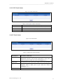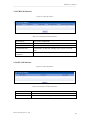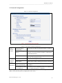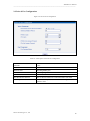
1
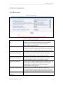
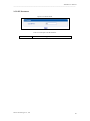
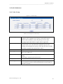
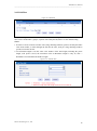
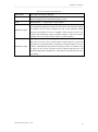
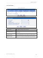
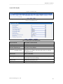
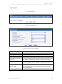
MTG200 User Manual V1.0
Dinstar Technologies Co., Ltd.
Address: Floor 6, Guoxing Building, Changxing Road, Nanshan District, Shenzhen, China 518057
Telephone:
+86-755-26456664
Fax:
+86-755-26456659
Emails:
[email protected], [email protected]
Website:
www.dinstar.com
1
MTG200 User Manual
___________________________________________________________________________________________
Amendment Records
File Name
Version
MTG200 User Manual
1.0
Date
Authors
01/08/2011
Technical Support Department
MTG200 User Manual
___________________________________________________________________________________________
Contents
1. OVERVIEW ......................................................................................................................................... 2
1.1 Product Introduction ........................................................................................................... 2
1.2 Equipment Structure............................................................................................................ 3
1.2.1 Rear View ................................................................................................................. 3
1.2.2 Front View................................................................................................................ 4
1.3 Functions and Features ........................................................................................................ 5
1.3.1 Protocol standard supported ..................................................................................... 5
1.3.2 System function........................................................................................................ 5
1.3.3 Industrial standards supported.................................................................................. 5
1.3.4 General hardware specification ................................................................................ 5
2. PARAMETER SETTING ..................................................................................................................... 6
2.1 Login ................................................................................................................................... 6
2.2 Status &Statistics ................................................................................................................ 7
2.2.1 System Information .................................................................................................. 7
2.2.2 E1/T1 Status ............................................................................................................. 8
2.2.3 PSTN Trunk Status ................................................................................................... 9
2.2.4 IP Trunk Status ......................................................................................................... 9
2.2.5 PRI Call Statistics .................................................................................................. 10
2.2.6 SIP Call Statistics ................................................................................................... 10
2.3 Network Configuration ..................................................................................................... 11
2.4Voice & Fax Configuration ................................................................................................ 12
2.5 Protocol Configuration ...................................................................................................... 13
2.5.1 PRI Parameter ........................................................................................................ 13
2.5.2 SIP Parameter ......................................................................................................... 14
2.6 Profile Definitions ............................................................................................................. 15
2.6.1 Coder Group ........................................................................................................... 15
2.6.2 Dial Plan................................................................................................................. 16
2.6.3 Dial Timeout .......................................................................................................... 18
2.6.4 PSTN Profile .......................................................................................................... 19
2.6.5 IP Profile ................................................................................................................ 20
2.7 Trunk Configuration .......................................................................................................... 21
2.7.1 E1/T1 Parameter..................................................................................................... 21
2.7.2 PRI Trunk ............................................................................................................... 22
2.7.3 SIP Trunk ............................................................................................................... 23
2.8 Management Configuration .............................................................................................. 25
2.8.1 Management Parameter .......................................................................................... 25
2.8.2 Data Backup ........................................................................................................... 26
2.8.3 Data Restore ........................................................................................................... 26
2.8.4 Version Information................................................................................................ 27
2.8.5 Firmware Upload ................................................................................................... 27
2.8.6 Modify Password ................................................................................................... 28
2.8.7 Restart Device ........................................................................................................ 28
MTG200 User Manual
___________________________________________________________________________________________
3.FAQ ..................................................................................................................................................... 29
3.1 How to get the IP address if I have modified the default IP or forgot it ? ......................... 29
3.2 Device have been connected to network physically, but the network cannot be connected
or network communication is not normal ............................................................................... 29
3.3 Equipment can’t register ................................................................................................... 29
4. GLOSSARY ....................................................................................................................................... 30
MTG200 User Manual
___________________________________________________________________________________________
1. Overview
1.1 Product Introduction
MTG200 series is a kind of digital trunk gateway based on embedded operating system. It
supports standard SIP protocol, with large-capacity carrier class telephone trunk gateway functions.
Currently it supports 1/2/4 E1/T1 interfaces and can realize intercommunication with mainstream
manufacturers soft switch system, and interwork with carrier's local Telephone exchange by PRI
interface. A typical network diagram shows the function of MTG200 as below.
Figure 1-1-1Application topology
Dinstar Technologies Co., Ltd.
2
MTG200 User Manual
___________________________________________________________________________________________
1.2 Equipment Structure
1.2.1 Rear View
Figure 1-2-1 MTG200 Rear View
Table 1-2-1 Description of MTG200 Rear View
PWR
The power interface. DC12V.1A
Port0-Port3
E1/T1 Port. There are 4E1 if you have buy a MTG200-4E1/T1
FE0
The Service Ethernet Interface, standard 10/100BASE-TX Ethernet interfaces.
Default IP address is 192.168.1.111,default subnet mask is 255.255.255.0
FE1
Management Ethernet Interface. Default IP address is 192.168.11.1, default
subnet mask is 255.255.255.0
Dinstar Technologies Co., Ltd.
3
MTG200 User Manual
___________________________________________________________________________________________
1.2.2 Front View
Figure 1-2-2 MTG200 Front View
Table 1-2 -2 Description of MTG200 Front View
LED
Color
Name
POWER
Green
Power status indicator
Status
Description
Off
Power is off
On
Power is on
Fast blinking
Register
Slow blinking
Unregister
Off
Normal
On
Failed
RUN
Green
Register indicator
ALM
Yellow
The failure of device indicator
RST
Reset button, it is used to restart the device
CONSOLE
RS232 console port: it can be used to debug and configure the device. The baud
rate is 115200 bps.
E1/T1
Indicating the connection state of device E1/T1. 0, 1,2,3indicates the connection
state of E1/T1 interfaces respectively
LINK
Indicating the connection state of the network . 0 indicates FE0 and 1 indicates
FE1
SPEED
Yellow
Dinstar Technologies Co., Ltd.
Off
10Mbps
On
100Mbps
Indicating the network bandwidth
4
MTG200 User Manual
___________________________________________________________________________________________
1.3 Functions and Features
1.3.1 Protocol standard supported
●
●
●
●
●
●
Standard SIP /PRI protocol
Dynamic Host Configuration Protocol (DHCP)
Point-to-Point Protocol over Ethernet (PPPoE)
Hypertext Transfer Protocol (HTTP)
Domain Name System (DNS)
ITU-T G.711A-Law/U-Law、G.723.1、G.729AB、iLBC(optional)
1.3.2 System function
●
●
●
●
●
PLC,VAD and CNG
DTMF mode: RFC 2833, SIP INFO and INBAND
T.38/ Pass-Through FAX over IP
HTTP/Telnet configuration
Firmware upgrade by TFTP/Web
1.3.3 Industrial standards supported
●
●
●
●
●
●
●
●
●
●
Stationary use environment: EN 300 019: Class 3.1
Storage environment: EN 300 019: Class 1.2
Transportation environment: EN 300 019: Class 2.3
Acoustic noise: EN 300 753
CE EMC directive 2004/108/EC
EN55022: 2006+A1:2007
EN61000-3-2: 2006,
EN61000-3-3: 1995+A1: 2001+A2: 2005
EN55024: 1998+A1: 2001+A2: 2003
Certifications: FCC, CE
1.3.4 General hardware specification
●
●
●
●
●
●
Power supply: 12VDC, 1A
Temperature: 0~40℃(operational),-20~70℃(storage)
Humidity: 10%~90%, no condensation
Max power consumption: 15W
Dimension(mm): 210*150*38
Net weight: 0.75kg
Dinstar Technologies Co., Ltd.
5
MTG200 User Manual
___________________________________________________________________________________________
2. Parameter setting
2.1 Login
Enter the IP of FE1 or FE0 in customer’s browser. FE1 default IP address is 192.168.11.1, FE0
default IP address is 192.168.1.111. It will request customer to input user name and password.
Default user name and password are “admin”.
If customer modified the default IP or forgot the IP, that can’t enter the configuration page. Please
connect PC and device serial with the serial line. Enter the CLI to view or modify the equipment
IP. Here IP is set to 172.16.33.62. In addition, hold down the RST button to restart the device,
customer can regain the port’s default IP. Then enter the IP address of device in the browser
address bar. Customer will see the following page.
Figure 2-1-1 Login interface
The default user name and password is "admin". To guarantee the system safety, when login for
the first time. The system will prompt the user to modify the password. The interface is shown as
below.
Figure 2-1-2 Modify Password
After inputting the old password, input a new password and confirm it by inputting it again.
Dinstar Technologies Co., Ltd.
6
MTG200 User Manual
___________________________________________________________________________________________
2.2 Status &Statistics
Show the status of trunk and statistics of call.
2.2.1 System Information
This configuration page includes general information and version information.
Figure 2-2-1 System Information
Table 2-2-1 Description of System Information
MAC address
MAC address of FE1 port.
Service Ethernet Mode
The network mode of FE1
Service Ethernet Interface
Include IP address、subnet mask、default gateway of FE1
Management Ethernet Interface
Include IP address、subnet mask of FE0
DNS Server
IP addresses of primary DNS server
System Up Time
Time elapsed from device power on to now
Traffic Statics
Total bytes of message received and sent by FE1 port
Equipment Type
Equipment type; this equipment is: MTG200
Hardware Version
Hardware version of device
DSP Version
Driver version
Web Version
Version of current WEB interface of device
Software Version
Software version of device running currently
Built Time
The build time of current software version
Dinstar Technologies Co., Ltd.
7
MTG200 User Manual
___________________________________________________________________________________________
2.2.2 E1/T1 Status
Figure 2-2-2 E1/T1 status
Table 2-2-2 Description of E1/T1 status
E1/T1 Port Status
1.LOS Alarm: Signal loss alarm, this alarm is created when receiving
is lost, please check the physical connection whether disconnected.
2.RRA Alarm: Receive Remote Alarm, when distant end detects LOS
alarm or LFA alarm, it will insert an alarm message to near end device
in transmit data, check the device of opposite terminal to see if it is
perfect.
3.AIS Alarm: Alarm indicating; during a time interval, when received
data is detected to have only 2 or less than 2 zeros, then AIS alarm is
created, check line device.
4.Disable: Means that this E1/T1 is not used.
5.ISDN/SS7 Signal Alarm: Means physical connection is normal,
signaling link has problem.
6.Active-OK: Means that physical connection and signaling link are
normal.
E1/T1 Channel Status
1.Non Voice: Non voice channel, which used as a synchronization
channel
2.Idle: Means this channel is idle, when the channel is enabled and the
cable is connected OK.
3.Signal: signal channel
4.Busy: Means this channel is occupied
5.Fault: when the channel is enabled and the cable is not connected.
6.Disable: Have not use this E1/T1 trunk
Dinstar Technologies Co., Ltd.
8
MTG200 User Manual
___________________________________________________________________________________________
2.2.3 PSTN Trunk Status
Figure 2-2-3 PSTN Trunk Status
Table 2-2-3 Description of PSTN Trunk Status
PRI Trunk No
The number of PRI trunk, each trunk corresponds to a PRI link
Trunk Name
Identification of the trunk can be remembered easily.
E1/T1 Port No
Indicate the E1/T1 line occupied by the PRI trunk.
Link Status
Indicate whether the PRI link is established.
2.2.4 IP Trunk Status
Figure 2-2-4 IPTrunk Status
Table 2-2-4 Description of IP Trunk Status
SIP Trunk No
The number of SIP trunk
Username
When SIP trunk is under registered mode, change the value in the
configuration shown in the account registration, If SIP trunk is
under non-registered mode, the value is meaningless, as '---'
Trunk Mode
Peer and Access, peer is peer to peer mode, access is access mode
Register Status
Indicate the status of SIP trunk ( access mode ) , register or
unregister, when is under peer to peer mode, the values is
meaningless, as '---'
Link Status
Established and Fault status.
Dinstar Technologies Co., Ltd.
9
MTG200 User Manual
___________________________________________________________________________________________
2.2.5 PRI Call Statistics
Figure 2-2-5 PRI call statistics
Table 2-2-5 Description of PRI call statistics
PRI Trunk No
The number of PRI trunk
Trunk Name
The name used to describe the PRI trunk
Current Calls
Number of lines that are being called currently
Accumulated Calls
Total number of calls from running start of system to current
time.
Percent of Call
Completed
The percent of calls completed in all calls.
2.2.6 SIP Call Statistics
Figure 2-2-6 SIP Call Statistics
Table 2-2-6 Description of SIP Call Statistics
SIP Trunk No
The number of SIP trunk
Trunk Name
The name used to describe the PRI trunk
Current Calls
Number of lines that are being called currently
Dinstar Technologies Co., Ltd.
10
MTG200 User Manual
___________________________________________________________________________________________
2.3 Network Configuration
Figure 2-3-1 Network Configuration
Table 2-3-1 Description of Network Configuration
Service
Ethernet
Interface
Manageme
nt Ethernet
Interface
DNS Server
Obtain IP address
automatically
If Selected, the MTG will obtain IP address via DHCP
Use the following IP
address
If Selected ,Set a static IP for Service Ethernet
Interface .You need to fill the IP address, Subnet Mask,
and Default Gateway
PPPoE
If users approach the net via PPPoE, please Select it and
fill your account and password.
IP Address
Fill the IP of Management Ethernet Interface
Subnet Mask
Fill the Subnet Mask of Management Ethernet Interface
Obtain DNS server
address automatically
If selected, the MTG will obtain DNS server IP address
via DHCP
Use the following DNS
server addresses
If selected, you need fill Primary DNS server addresses ,
the secondary DNS Server is Optional
Note: FE0 port IP and FE1 port IP should be set in different segments. After configure the network
address, and restart the gateway configuration to take effect.
Dinstar Technologies Co., Ltd.
11
MTG200 User Manual
___________________________________________________________________________________________
2.4Voice & Fax Configuration
Figure 2-4-1 Voice & Fax Configuration
Table 2-4-1 Description of Voice & Fax Configuration
Disconnect Call on Silence
Detection
Silence time out is detected, end of the call when selected
“Yes”
Silence Detection Period
The interval time of silence detection
PSTN in Gain
Incoming PSNT gain
IP in Gain
Incoming IP gain
PSTN in No Answer Timeout
The no answer timeout of a call which make from PSTN
IP in No Answer Timeout
The no answer timeout of a call which make from VoIP
Fax Transport Mode
Two modes are provided: T.38 and Pass-through, default
option is T.38
Dinstar Technologies Co., Ltd.
12
MTG200 User Manual
___________________________________________________________________________________________
2.5 Protocol Configuration
2.5.1 PRI Parameter
Figure 2-5-1 PRI Parameter
Table 2-5-1 Description of PRI Parameter
Calling Party Numbering
Plan
Provide 6 plans: Unknown, ISDN/Telephony numbering plan, data
numbering plan, telegraph numbering plan, national standard
numbering plan, private numbering plan. The default is
ISDN/Telephony numbering plan.
Calling Party Number Type
6 optional types are provided for calling party: Unknown,
International number, National number, Network special number,
User number, Short code dialing. The default option is Unknown.
Screening Indicator for
Displaying Caller Number
4 options available: User provider, no shield; User provide, check
and send; User provide, check and having failure; Network
provide. The default option is: User provider, no shield.
Screening Indicator for No
Displaying Caller Number
4 options available: User provider, no shield; User provide, check
and send; User provide, check and having failure; Network
provide. The default option is: User provider, no shield.
Called Party Numbering
Plan
Provide 6 plans: Unknown, ISDN/Telephony numbering plan, data
numbering plan, telegraph numbering plan, national standard
numbering plan, private numbering plan. The default is
ISDN/Telephony numbering plan.
Called Party Number Type
6 optional types are provided for called party: Unknown,
International number, National number, Network special number,
User number, Short code dialing. The default option is Unknown.
Information Transfer
Capability
Support speech and 3.1khz audio
Dinstar Technologies Co., Ltd.
13
MTG200 User Manual
___________________________________________________________________________________________
2.5.2 SIP Parameter
Figure 2-5-2 SIP Parameter
Table 2-5-2 Description of SIP Parameter
Local SIP Port
Dinstar Technologies Co., Ltd.
Local SIP monitoring port, the default is 5060
14
MTG200 User Manual
___________________________________________________________________________________________
2.6 Profile Definitions
2.6.1 Coder Group
Figure 2-6-1 Coder Group
Table 2-6-1 Description of Coder Group
Coder Group
Used for configure the voice codec parameters, through it can
configured voice capabilities into 8 groups, each group can have
different audio capabilities, such as the priority of voice codec,
packaging length and whether to support silence suppression
Coder Group ID
ID standard for Voice Ability, total with 8 groups, where 0 is the default
group ID number, the codec that MTG equipment support in the
grouping will be displayed in 0 group ,on the map only shows 4 kinds ,
mean MTG equipment only support this 4 codecs.
Coder Name
Support 4 kinds of audio codec. G711A/G711U/G729/G723/iLBC
Payload Type
Coder name is the interpretation of the field, each codec has a unique
value, refer to RFC3551
Packetization Time(ms)
Voice Codec packetization time, you can define different kinds of
coding
and decoding, minimum packetization time
Rate(kbps/s)
The proportion of the data-stream that is useful
Silence Suppression
It is disabled by default. During talking, the bandwidth occupied by
voice transmission will be released automatically for silence party or
when talk is paused.
Dinstar Technologies Co., Ltd.
15
MTG200 User Manual
___________________________________________________________________________________________
2.6.2 Dial Plan
Figure 2-6-2 Dial Plan
Dial plan configuration used to receive numbers, you can configure different prefix number, these
rules can be divided into 5 groups, separate with a dial plan ID, where 0 is the default setting.
Notes:
1. In order to ensure each rule can take effect, long matching numbers (prefix) rule dial plan index
value need smaller, so when through the file into the rules, need put t long matching numbers
(prefix) rule before the file
2. No maximum length is 30, this value is the number of the total length, including the prefix
length, such prefix is 0755, the maximum value of Maximum Length is only 26, and "."
Wildcard is not included in the number length
Figure 2-6-3 Add Dial Plan
Dinstar Technologies Co., Ltd.
16
MTG200 User Manual
___________________________________________________________________________________________
Table 2-6-2 Description of Add Dial Plan
Dial Plan ID
The number to identify a dial plan
Dial Plan Index
Dial plan priority rules take effect in accordance with dial plan index size,
and not according to the maximum number received.
Prefix
Match number, "." representative of any number
Minimum Length
The minimum receiving Number length (0 to 30). If receive a number equal
to the minimum length greater than, less than equal to the maximum length,
the number will be used to continue the call. If the maximum length,
determine the number to receive a complete, will no longer receive a new
number, and immediately began to number analysis, if there are numbers
continue to be received, the system will give up these numbers.
Maximum Length
The largest Received number length (0 to 30), the maximum number length
that can be received, if the received number in this length, the system will
determine the receiving number is completed, no longer continue to receive
numbers, immediately begin numbers analyzed, If there are numbers keep
to send over, the system will drop the new numbers dial plan rules can
through management configuration-> Data Restore into dial plan, the file is
a txt format.
Dinstar Technologies Co., Ltd.
17
MTG200 User Manual
___________________________________________________________________________________________
2.6.3 Dial Timeout
Figure 2-6-4 Dial Timeout
Figure 2-6-5 Add Dial Timeout
Table 2-6-3 Description of Add Dial Timeout
Dial timeout ID
The number to identify a dial timeout rule
description
Description of dial timeout
Initial Digit Timeout
Generally refer to the time from user dial first digit to harvest in
prefix number
Before Minimum Number
Length Timeout(S)
After receiving prefix number, the number has not yet reached the
length of the minimum receiving number, the length of timeout
After Minimum Number
Length Timeout(S)
After receiving number, the number has reached the minimum
length, but not reached the maximum length of the dial timeout
Dinstar Technologies Co., Ltd.
18
MTG200 User Manual
___________________________________________________________________________________________
2.6.4 PSTN Profile
Figure 2-6-6 PSTN Profile
PSTN profile is used to configure PSTN call number rules and parameter.
Figure 2-6-7Add PSTN Profile
Table 2-6-4 Description of Add PSTN Profile
PSTN Profile ID
The number to PSTN Profile
Description
Description of the PSTN Profile
Code Group ID
Refer to "Coder Group"
RFC2833 Payload Type
The item is 101 by default
1st/2nd/3rd Tx DTMF Option
There are three ways to send DTMF: RFC2833/SIP INFO/
INBAND, in accordance with the priority choice to send the
configuration mode
Dial Plan ID
Refer to "Dial Plan"
Dial Timeout ID
Refer to "Dial Timeout"
Receiving of Overlap Dialing
Not enabled by default, only enable this feature, “Dial plan” and
“Dial timeout” have the meaning
Remove CLI
Default does not remove CLI
Play busy tone to PSTN
Equipment will play busy tone from IP to PSTN
Dinstar Technologies Co., Ltd.
19
MTG200 User Manual
___________________________________________________________________________________________
2.6.5 IP Profile
Figure 2-6-8 IP Profile
Figure 2-6-9 Add IP Profile
Table 2-6-5 Description of Add IP Profile
IP Profile ID
The number to mart the IP Profile
Description
Description of the PSTN Profile
Declare RFC2833 in SDP
Support by default
Support Early Media
Whether support Early Media(183)
Play Ringback Tone to
PSTN from
I IP-> PSTN call ring back tone player side, if set to local, it will
play from the equipment and set to IP , it will play by the called
Play Ringback Tone to IP
from
PSTN->IP call ring back tone player side, if set to local, it will play
from the equipment and set to PSTN, it will play by the called
Wait Peer RTP
If set to No, will auto send RTP packets during the call, if set to Yes,
will wait the RTP packet was sent by the opposite end first ,then
send out RTP packets
T.30 SDP Expand Type
T30 extended types in SDP: Huawei/ZTE
Dinstar Technologies Co., Ltd.
20
MTG200 User Manual
___________________________________________________________________________________________
2.7 Trunk Configuration
2.7.1 E1/T1 Parameter
Figure 2-7-1 E1/T1 Parameter
Figure 2-7-2 Modify E1/T1 Parameter
Table 2-7-1 Description of Modify E1/T1 Parameter
Work Mode
E1 or T1, the default is E1
PCM Mode
PCM mode: A LAW and Mu LAW, the default is A LAW
Frame Mode
The frame modes of E1/T1 are: DF, CRC-4, CRC4_ITU, the default is
CRC-4; the frame modes of T1 are: F12, F4, ESF, F72, the default is F4
Line Code
Line codes of E1/T1 are: NRZ, CMI, AMI, HDB3, the default is HDB3. The
line codes of T1 are: NRZ, CMI, AMI, B8ZS, the default is B8ZS
Dinstar Technologies Co., Ltd.
21
MTG200 User Manual
___________________________________________________________________________________________
2.7.2 PRI Trunk
Figure 2-7-3 PRI Trunk
In this configuration page, users can “Add”, “Delete”, “Modify” PRI trunk.
Figure 2-7-4 Add PRI Trunk
Table 2-7-1 Description of Add PRI Trunk
Select Trunk No
The number of PRI trunk; when you add PRI trunk, 0~7 number will appear
in the pull-down box to be selected (the number here depends on E1/T1
physical port number actually existed in MTG). After trunk number is
established, fill in corresponding port number in “E1/T1 Port No.”, so as to
assign E1/T1 to designated trunk; each PRI trunk corresponds to a E1/T1
port, if it is required to share D channel by several E1/T1, please refer to
“PSTN trunk binding” in route configuration.
PRI Trunk Name
Identification of PRI trunk, which can be remembered easily
PRI ID
Identification of PRI trunk number to outside (switch side), this number
definition generally begin from 0
Is D channel
Indicate whether this E1/T1 has D channel, the default is YES, which means
it has D channel.
E1/T1 Port No
E1/T1 port number is numbered according to the physical position sequence
of E1/T1, it generally begins from 0.
Standard Type
Interface type of PRI, two types available: ISDN and QSIG; the default is
ISDN.
ISDN Terminal
Side
Indicate PRI network property of E1/T1, it is divided into: “User side” and
“Network side”. When PRI loopback is carried out, the network properties
of E1/T1 port at both receiving and sending sides must be different.
ISDN Ring signal
The ring signal include Alerting and progress
PSTN profile ID
Refer to PSTN profile
Dinstar Technologies Co., Ltd.
22
MTG200 User Manual
___________________________________________________________________________________________
2.7.3 SIP Trunk
Figure 2-7-5 SIP Trunk
Click “Add” to add a SIP Trunk. If costomer want to delete or modify a SIP Trunk, please select
the SIP Trunk you want to operation.
Figure 2-7-6 Add SIP Trunk
Dinstar Technologies Co., Ltd.
23
MTG200 User Manual
___________________________________________________________________________________________
Table 2-7-3 Description of Add SIP Trunk
Trunk No
The range of number is 1~50
Trunk Name
It can be edited freely, which can be identified and remembered easily.
Registration to
Remote Party
Defined by IETF work group RFC3372, it is a standard used to establish
communication between SIP and ISUP; the default is “Yes”; if SIP
trunk does not support, then set it to “No”.
Call mode
Whether register request message to far-side equipment will be sent or
not, you can select “Yes” or “No”. There are two modes: peer and
access
SIP Username
SIP user name which registers to soft switch/SIP server
SIP Password
SIP password which registers to soft switch/SIP server
Confirm SIP Password
Make sure the password matches the password entered above
Expire Time
Time interval of sending register request message to opposite equipment
each time; the range is from 1-3600 seconds.
IP Profile ID
Refer to IP Profile
Detect Link Status
If select it, the MTG200 will send HEARTBEAT message to peer to
make sure the link status is OK.
Remote IP
IP address of remote platform interfacing with this MTG.
Remote Port
Q.931 port of SIP of remote platform interfacing with this MTG, the
default is 5060
Incoming SIP
Authentication Type
You can select IP address authentication or password authentication,
when “IP Address” authentication is selected, the calling initiated from
remote will not subject to domain name or password authentication, only
judge whether the IP address is legal or not; if “No” is selected,
authentication realm/password authentication will be carried out.
Password
It constitutes SIP protocol safety authentication together with domain
name of authentication.
Confirm Password
Input password again to verify password
IP to PSTN Limitation
IP to PSTN calls; the range is 0~65535, the default is no limitation; If
Yes is selected, then input limited calls in the edit box appeared.
PSTN to IP Limitation
PSTN to IP calls, the range is 0~65535; the default is no limitation; If
Yes is selected, then input limited calls in the edit box appeared.
IP to PSTN Time
Control
The default setting is disabled. If Enabled is selected, then you can edit
the start and stop time of prohibition time interval. Within this time
interval, all calls from IP to PSTN are prohibited. (Calls from PSTN to
IP are not limited)
Enable SIP Trunk
A switch used to enable this SIP trunk or not; you can select “Yes” or
“No”, when “No” is selected, this SIP trunk is invalid.
Dinstar Technologies Co., Ltd.
24
MTG200 User Manual
___________________________________________________________________________________________
2.8 Management Configuration
2.8.1 Management Parameter
Figure 2-8-1 Management Parameter
Table 2-8-1Description of Management Parameter
WEB Port
Listening port of local WEB service, the default is 80.
Telnet Port
Listening port of local Telnet service, the default is 23.
Syslog Enable
The default is “No”.
Server Address
Address for saving system log.
Syslog Level
None, Debug, Notice, Warning and Error
NTP Enable
Simple Network Management Protocol is enabled or not; the default is No.
Primary NTP server
Address
The Primary IP address of SNMP management host computer. The host
computer of the IP address will carry out monitoring and management to
MTG.
Primary NTP server
Port
The port where managed device (MTG) provides trap message (it is
generally alarm message) to SNMP management host computer, the default
is 123.
Secondary NTP
server Address
The Secondary IP address of SNMP
Secondary NTP
server Port
The port of the Secondary IP address of SNMP
Check Interval
Time interval of check
Time Zone
The time zone of local
Dinstar Technologies Co., Ltd.
25
MTG200 User Manual
___________________________________________________________________________________________
2.8.2 Data Backup
Figure 2-8-2 Data Backup
Table 2-8-2 Description of Data Backup
database
Click the Backup, and save the database in your PC
dialplan
Click the Backup, and save the dialplan in your PC
exception
Click the Backup, and save the exception in your PC
2.8.3 Data Restore
Figure 2-8-3 Data Restore
Table 2-8-3 Description of Data Restore
Database
Click "Browse" to select the Database file, and then click "Restore".
Dialplan
Click "Browse" to select the Dialplan file, and then click "Restore".
Dinstar Technologies Co., Ltd.
26
MTG200 User Manual
___________________________________________________________________________________________
2.8.4 Version Information
Figure 2-8-4 Version Information
Table 2-8-4 Description of Version Information
Software
The information of firmware
Database
The information of database
Web
The information of Web software
2.8.5 Firmware Upload
Figure 2-8-5 Firmware Upload
Table 2-8-5 Description of Firmware Upload
Software
Click "Browse" to select the firmware , and then click "Upload".
Web
Click "Browse" to select the Web software, and then click "Upload".
Dinstar Technologies Co., Ltd.
27
MTG200 User Manual
___________________________________________________________________________________________
2.8.6 Modify Password
Figure 2-8-6 Modify Password
Table 2-8-6 Description of Modify Password
Old Password
Current password
New Password
The new password
Confirm Password
verify password
2.8.7 Restart Device
Figure 2-8-7 Restart Device
If you click Restart, a message ("Are you sure?") will be popped up, and then click OK.
Dinstar Technologies Co., Ltd.
28
MTG200 User Manual
___________________________________________________________________________________________
3. FAQ
3.1 How to get the IP address if I have modified the default IP or forgot it ?
Customers have two ways to get the IP address:
1) Press the RST button, then users can regain default IP. Refer to 1.2.1 Front View
2) Connect the CONSOLE with your PC Serial Port. The baud rate is 115200 bps. The user name
is "admin",password is telnet/web login password. If password is reset, the default password is
“admin”. When customers have accessed it and input the command "show int" to get the IP.
3.2 Equipment physical connection to normal, but the network cannot be connected or
network communication is not normal
1) Make sure the network cable is ok or not , can through view the device WAN port or LAN port
indicator light to determine the work states of physical connection
2) Makeing sure the connected network devices (router, switch or hub) support 10M/100M
adaptive.
Else, connecting the Equipment directly to PC and landing Web , then in the "local
connection" .Selecting the correct Ethernet Work Mode
3) Check whether there is a LAN port conflict with the existing IP address
4) Login using the serial port, in the enable mode to view the correct IP and mask, and ping the
same segment of the PC or device to see if can pass.
3.3 Equipment can’t register
If the Run LED flashes slowly ,it means unregistered.
1) Check the network connection is working (see above section), whether the Configuration is
correct
2) Check whether the LAN firewall setting is inappropriate (such whether limit the network
Communication); If it is, there are two ways to try to resolve:
(2.1) Ask network administrators to open limitation with the equipment’s network
communications (it is a special equipment, not afraid of virus attacks);
(2.2) Try to enable the equipment tunnel (Through the WEB for Configuration, Also, please
NOTE, open the tunnel will impact voice quality, Please do not enable the tunnel as far as
possible, reference WEB Configuration Interface, Description section).
4) Check whether the Local Network to the SIP PROXY platform network environment is
relatively poor or not, and if so, please check Local Network or contact the service provider.
5) If go through those steps, the device still be in trouble, please contact the equipment provider.
Dinstar Technologies Co., Ltd.
29
MTG200 User Manual
___________________________________________________________________________________________
4. Glossary
PRI: Primary rate interface
DND: Do-not-Disturb
FMC: Fixed Mobile Convergence
SIP: Session Initiation Protocol
DTMF: Dual Tone Multi Frequency
USSD: Unstructured Supplementary Service Data
PSTN:Public Switched Telephone Network
STUN: Simple Traversal of UDP over NAT
IVR: Interactive Voice Response
IMSI: International Mobile Subscriber Identification Number
IMEI: International Mobile Equipment Identity
DMZ: Demilitarized Zone
Dinstar Technologies Co., Ltd.
30