1
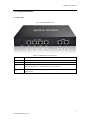
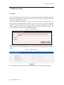
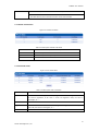
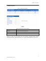
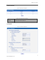
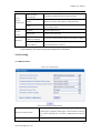
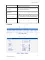
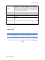
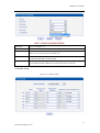
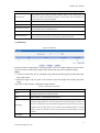
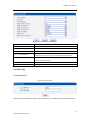
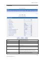
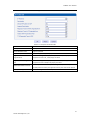
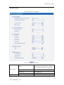
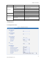
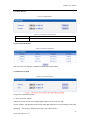
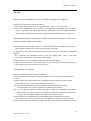
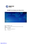
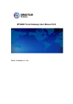
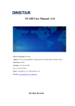
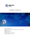
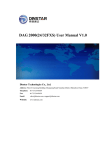
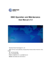
MTG200 Trunk Gateway User Manual V2.0
Dinstar Technologies Co., Ltd.
Address:
Floor 6 Guoxing Building Changxing Road Nanshan District Shenzhen China 518052
Telephone: 86-755-26456664
Fax:
86-755-26456659
Email:
[email protected], [email protected]
Website:
www.dinstar.com
MTG200 User Manual
Revision Records
File Name
MTG200 User Manual
Document Version
2.0
Firmware Version
2.01.01.01
Date
17/04/2012
Revised by
Technical Support Department
MTG200 User Manual
Content
1. PRODUCT INTRODUCTION .............................................................................................................. 1
1.1 Overview ............................................................................................................................. 1
1.2 Equipment Structure............................................................................................................ 2
1.2.1 Rear View ................................................................................................................. 2
1.2.2 Front View ................................................................................................................ 3
1.2.3 RJ-48c Line sequence .............................................................................................. 4
1.3 Functions and Features ........................................................................................................ 4
1.3.1 Protocol standard supported ..................................................................................... 4
1.3.2 System Function ....................................................................................................... 4
1.3.3 Industrial standards supported .................................................................................. 5
1.3.4 General hardware specification ................................................................................ 5
2. PARAMETER SETTING ..................................................................................................................... 6
2.1 Login ................................................................................................................................... 6
2.2 Status &Statistics ................................................................................................................ 7
2.2.1 System Information .................................................................................................. 8
2.2.2 E1/T1 Status ............................................................................................................. 9
2.2.3 PSTN Trunk Status ................................................................................................. 10
2.2.4 IP Trunk Status ....................................................................................................... 10
2.2.5 PRI Call Statistics................................................................................................... 11
2.2.6 SIP Call Statistics ................................................................................................... 12
2.3 Network............................................................................................................................. 12
2.4 PRI Config ........................................................................................................................ 13
2.4.1 PRI Parameter ........................................................................................................ 13
2.4.2 PRI Trunk ............................................................................................................... 14
2.5 PSTN Group Config.......................................................................................................... 15
2.5.1 E1/T1 Parameter..................................................................................................... 15
2.5.2 Coder Group ........................................................................................................... 16
2.5.3 Dial Plan................................................................................................................. 17
2.5.4 Dial Timeout .......................................................................................................... 18
2.5.5 PSTN Profile .......................................................................................................... 18
2.6 SIP Config ......................................................................................................................... 19
2.6.1 SIP Parameter ......................................................................................................... 19
2.6.2 SIP Trunk ............................................................................................................... 20
2.7 IP Group Config ........................................................................................................ 21
2.7.1 IP Profile ................................................................................................................ 21
2.8 Voice & Fax....................................................................................................................... 23
2.9 Maintenance ...................................................................................................................... 24
2.9.1 Management Parameter .......................................................................................... 24
2.9.2 Data Restore ........................................................................................................... 25
MTG200 User Manual
2.9.3 Data Restore ........................................................................................................... 26
2.9.4 Version Information................................................................................................ 26
2.9.5 Firmware Upload ................................................................................................... 26
2.9.6 Password Modification ........................................................................................... 27
2.9.7 Device Restart ........................................................................................................ 27
3.FAQ ............................................................................................................................................... 28
3.1 How to get the IP address if I have modified the default IP or forgot it ? ......................... 28
3.2 Equipment physical connection to normal, but the network cannot be connected or
network communication is not normal .................................................................................... 28
3.3 Equipment can’t register................................................................................................. 28
4. GLOSSARY .................................................................................................................................... 29
MTG200 User Manual
1. Product Introduction
1.1 Overview
MTG200 is a kind of digital trunk gateway based on embedded operating system, and
designed for IPPBX and call center. MTG200 provides 1/2/4*E1/T1 interfaces for users.
MTG200 mainly provide E1/T1 interface for small and medium enterprise. It supports rich
GUI configuration and 120 road traffic, and the user setting and maintaining system easily. A
typical network diagram shows the function of MTG200 as below.
Figure 1-1-1 Application topology
1
Dinstar Technologies Co., Ltd.
MTG200 User Manual
1.2 Equipment Structure
1.2.1 Rear View
Figure 1-2-1 MTG200 Rear View
Table 1-2-1 MTG200 Rear View Description
Interface
Description
PWR
The power interface. DC12V.1A
Port0-Port3
E1/T1 Port. There are 4E1 options.
FE0
FE1
The Service Ethernet Interface, standard 10/100BASE-TX Ethernet interfaces. Default IP
address is 192.168.1.111,default subnet mask is 255.255.255.0
Management Ethernet Interface. Default IP address is 192.168.11.1, default subnet mask is
255.255.255.0
2
Dinstar Technologies Co., Ltd.
MTG200 User Manual
1.2.2 Front View
Figure 1-2-2 MTG200 Front View
Table 1-2 -2 MTG200 Front View Description
LED
Function
Color
POWER
Power status indicator
Green
RUN
Register indicator
Green
ALM
RST
CONSOLE
The failure of device
indicator
Yellow
Work Status
Off:Power is off
On: Power is on
Slow blinking: Unregister
Fast blinking: Register
Off: Normal
On: Failed
Reset button, it is used to restart the device
RS232 console port: it can be used to debug and configure the device. The baud rate is 115200
bps.
Off:E1/T1 port connection normal
E1/T1
Indicating the connection
state of device E1/T1.
Green
On: E1/T1 port connection and sending/ receiving
message normal
Flash:E1/T1 port connection failed
LINK
Indicating the connection
state of the network
Off: Network connection failed
Green
On: Network connection normal, and 0 indicates FE0
and 1 indicates FE1
SPEED
Indicating the network
bandwidth
Yellow
Off:10Mbps bandwidth
On:100Mbps bandwidth
3
Dinstar Technologies Co., Ltd.
MTG200 User Manual
1.2.3 RJ-48c Line sequence
MTG200 trunk gateway adopts standard RJ-48C interface and impedance value is 120Ω.
Connected end device by cross lines sequence.
1.3 Functions and Features
1.3.1 Protocol standard supported
● Standard SIP /PRI protocol
● Dynamic Host Configuration Protocol (DHCP)
● Point-to-Point Protocol over Ethernet (PPPoE)
● Hypertext Transfer Protocol (HTTP)
● Domain Name System (DNS)
● ITU-T G.711A-Law/U-Law、G.723.1、G.729AB、iLBC (optional)
1.3.2 System Function
● Comfort Noise Generation (CNG)
● Voice Activity Detection (VAD)
● Adaptive (Dynamic) Jitter Buffer (DJB)
● DTMF mode: RFC 2833, SIP INFO and INBAND
● T.38/ Pass-Through FAX over IP
● HTTP/Telnet configuration
● Firmware upgrade by TFTP/Web
4
Dinstar Technologies Co., Ltd.
MTG200 User Manual
1.3.3 Industrial standards supported
● Stationary use environment: EN 300 019: Class 3.1
● Storage environment: EN 300 019: Class 1.2
● Transportation environment: EN 300 019: Class 2.3
● Acoustic noise: EN 300 753
● CE EMC directive 2004/108/EC
● EN55022: 2006+A1:2007
● EN61000-3-2: 2006,
● EN61000-3-3: 1995+A1: 2001+A2: 2005
● EN55024: 1998+A1: 2001+A2: 2003
● Certifications: FCC, CE
1.3.4 General hardware specification
● Power supply: 12VDC, 1A
● Temperature: 0~40℃ (operational),-20~70℃(storage)
● Humidity: 10%~90%, no condensation
● Max power consumption: 15W
● Dimension (mm): 210*150*38
● Net weight: 0.75kg
5
Dinstar Technologies Co., Ltd.
MTG200 User Manual
2. Parameter setting
2.1 Login
First, device FE0 port connect PC with string, and then fill FE0 IP address in browser, FE0 default
IP address is 192.168.1.111. It will request customer to input user name and password. Default
user name and password are “admin”.
If customer modified the default IP or forgot the IP, that can’t enter the configuration page.
Please connect PC and device serial with the serial line. Enter the CLI to view or modify the
equipment IP. Here IP is set to 172.16.33.60. In addition, hold down the RST button to restart the
device, customer can regain the port’s default IP. Then enter the IP address of device in the
browser address bar. Customer will see the following page.
Figure 2-1-1 Login Interfaces
The default user name and password is "admin". To guarantee the system safety, when login for
the first time. The system will prompt the user to modify the password. The interface is shown as
below.
Figure 2-1-2 Modify Password
After inputting the old password, input a new password and confirm it by inputting it again.
6
Dinstar Technologies Co., Ltd.
MTG200 User Manual
2.2 Status &Statistics
Users through to traverse the left navigation tree, and can complete view, edit and configuration
device in the right configuration interface.
MTG configuration flow chart below:
7
Dinstar Technologies Co., Ltd.
MTG200 User Manual
2.2.1 System Information
This configuration page includes general information and version information.
Figure 2-2-1 System Information
Table 2-2-1 Description of System Information
MAC address
Hardware address of FE0 port
Service Ethernet Mode
Network mode of FE0, include: static and DHCP.
Service Ethernet Interface
Include: IP address, subnet mask, FE0 port default gateway
Management Ethernet Interface
Include IP address、subnet mask of FE1
DNS
DNS server IP address
System Up Time
Time elapsed from device power on to now
Traffic Statics
Total bytes of message received and sent by FE0 port
Equipment Type
Equipment type; this equipment is: MTG200
Hardware Version
Hardware version of device
DSP Version
Digital signal processing chip driver version
Web Version
Version of current WEB interface of device
Software Version
Software version of device running currently
Built Time
The build time of current software version
8
Dinstar Technologies Co., Ltd.
MTG200 User Manual
2.2.2 E1/T1 Status
Figure 2-2-2 E1/T1 Status
Table 2-2-2 Description of E1/T1 status
1. LOS Alarm: Signal loss alarm, this alarm is created when receiving is lost; please check
the physical connection whether disconnected.
2. RAI Alarm: Receive remote alarm indication, it is a signal transmitted in the outgoing
direction when a terminal determines that it has lost the incoming signal. Receiving
remote alarm indication (RAI) means the far-end equipment over the T1 line has a
problem with the signal it is receiving from the upstream equipment.
3. AIS Alarm: The Alarm Indication Signal (AIS) failure is declared when an AIS defect is
E1/T1 Port Status
detected at the input and the AIS defect still exists after the Loss of frame failure which is
caused by the unframed nature of the 'all-ones' signal is declared. The AIS failure is
cleared when the Loss Of Frame failure is cleared.
4. Disable: Means that this E1/T1 is not used.
5. ISDN/SS7 Signal Alarm: Means physical connection is normal, signaling link has
problem.
6. Active-OK: Means that physical connection and signaling link are normal.
1.Frame-Sync: Non voice channel, which used as a synchronization channel
2.Idle: Means this channel is idle, when the channel is enabled and the cable is
connected OK.
3.Signal: Signal channel
E1/T1Channel Status
4.Busy: Means this channel is occupied by voice
5. Fault: The channel is enabled but the cable is not connected.
6.Disable: Have not use this E1/T1 trunk
7.L-blocked:
Local blocked, means that communication can only be initiated from local
8.R-blocked:
9
Dinstar Technologies Co., Ltd.
MTG200 User Manual
Remote blocked, means that communication can only be initiated from remote
9.B-blocked:
Both Sides blocked, means that the two sides cannot communication
2.2.3 PSTN Trunk Status
Figure 2-2-3 PSTN Trunk Status
Table 2-2-3 Description of PSTN Trunk Status
PRI Trunk No
The number of PRI trunk, each trunk corresponds to a PRI link
Trunk Name
Used to identify the name of the trunk
E1/T1Port No
Indicate the E1/T1 line occupied by the PRI trunk.
Link Status
Indicate whether the PRI link is established.
2.2.4 IP Trunk Status
Figure 2-2-4 IP Trunk Status
Table 2-2-4 Description of IP Trunk Status
SIP Trunk No
The number of SIP trunk
Username
When SIP trunk is under registered mode, change the value in the configuration shown in
the account registration, If SIP trunk is under non-registered mode, the value is
meaningless, as '---'
Trunk Mode
Peer and Access two modes
Register Status
Indicate the status of SIP trunk(access mode), register or unregister, when is under peer to
peer mode, the values is meaningless, as '---'
Link Status
Established and Fault status.
10
Dinstar Technologies Co., Ltd.
MTG200 User Manual
2.2.5 PRI Call Statistics
Figure 2-2-5 PRI Trunk Call Statistics
Table 2-2-5 PRI Description of PRI call statistics
PRI Trunk No
The number of PRI trunk
Trunk Name
The name used to describe the PRI trunk
Current Calls
Number of lines that are being called currently
Accumulated Calls
Total number of calls from running start of system to current time.
ASR
The percent of calls completed in total calls.
This statistics page show the reasons for release of the call, including: Normal Call Clearing, Call
Rejected, User Busy, No User Response, No Circuit Available, Unassigned Number, Normal
Unspecified and others. Statistical information in an intuitive would be reflected on the pie char.
11
Dinstar Technologies Co., Ltd.
MTG200 User Manual
2.2.6 SIP Call Statistics
Figure 2-2-6 SIP Trunk Call Statistics
Table 2-2-6 Description of SIP Call Statistics
SIP Trunk No
The number of SIP trunk
Trunk Name
The name used to describe the PRI trunk
Current Calls
Number of lines that are being called currently
2.3 Network
Figure 2-3-1 Network Configuration
12
Dinstar Technologies Co., Ltd.
MTG200 User Manual
Table 2-3-1 Description of Network Configuration
Obtain IP address
Service
Ethernet
Interface (FE0)
If Selected, the MTG will obtain IP address via DHCP
automatically
Use the following IP
If Selected ,Set a static IP for Service Ethernet Interface .Need
address
to fill the IP address, Subnet Mask, and Default Gateway
If users approach the net via PPPoE, please Select it and fill your
PPPoE
Management
account and password.
IP address
Fill the IP address of FE1
Subnet mask
Fill the subnet mask of FE1
Ethernet
Interface
Obtain DNS server
DNS Server
If selected, the MTG will obtain DNS server IP address via DHCP
address automatically
Use the following DNS
If selected, you need fill Primary DNS server addresses, the
server addresses
secondary DNS Server is optional.
Ntoe:FE0 port IP and FE1 port IP should be set in different segments. After configure the
network address, and restart the gateway configuration to take effect.
2.4 PRI Config
2.4.1 PRI Parameter
Figure 2-4-1 PRI Parameter
Table 2-4-1 Description of PRI Parameter
Provide six plans: Unknown, ISDN/Telephony numbering plan, data
Calling Party Numbering Plan
numbering plan, telegraph numbering plan, national standard numbering
plan, private numbering plan. The default is ISDN/Telephony numbering
plan.
Calling Party Number Type
Six optional types are provided for calling party: Unknown, International
13
Dinstar Technologies Co., Ltd.
MTG200 User Manual
number, National number, Network special number, User number, Short
code dialing. The default option is Unknown.
Screening Indicator for Displaying
Caller Number
Screening Indicator for No Displaying
Caller Number
Four options available: User provider, no shield; User provide, check and
send; User provide, check and having failure; Network provide. The
default option is: User provider, no shield.
Four options available: User provider, no shield; User provide, check and
send; User provide, check and having failure; Network provide. The
default option is: User provider, no shield.
Provide six plans: Unknown, ISDN/Telephony numbering plan, data
Called Party Numbering Plan
numbering plan, telegraph numbering plan, national standard numbering
plan, private numbering plan. The default is ISDN/Telephony numbering
plan.
Six optional types are provided for called party: Unknown, International
Called Party Number Type
number, National number, Network special number, User number, Short
code dialing. The default option is Unknown.
Information Transfer Capability
Support speech and 3.1khz audio. The default option is speech.
2.4.2 PRI Trunk
Figure 2-4-2 PRI Trunk
Click “Add” to add a PRI Trunk. If user want to delete or modify a PRI Trunk, please select the
PRI Trunk user want to do.
Figure 2-4-3 PRI Trunk Add
14
Dinstar Technologies Co., Ltd.
MTG200 User Manual
Table 2-4-2 Description of Add PRI Trunk
The number of PRI trunk; when user add PRI trunk, 0~7 number will appear in the
pull-down menu to be selected (the number here depends on E1/T1 physical port
Trunk No
number actually existed in equipment). After trunk number is established, filling in
corresponding port number in “E1/T1 Port No.”, so as to assign E1/T1 to designated
trunk; Each PRI trunk corresponds to a E1/T1 port.
Trunk Name
Description of PRI trunk
Channel ID
Channel ID of E1/T1 ports, this number definition generally starts from 0.
D-channel
Indicate whether E1/T1 supports D channel, the default is Yes.
E1/T1 Port No
Protocol
E1/T1 port number is numbered according to the physical position of E1/T1, it generally
starts from 0.
Interface type of PRI. There are two types are available: ISDN and QSIG; the default is
ISDN.
Indicate PRI network property of E1/T1, it is divided into: “User side” and“Network
Switch Side
side”. When PRI loopback is carried out, the network properties of E1/T1 port at both
receiving and sending sides must be different.
Alerting Indication
The ring signal include Alerting and Progress
2.5 PSTN Group Config
2.5.1 E1/T1 Parameter
Figure 2-5-1 E1/T1 Parameter
15
Dinstar Technologies Co., Ltd.
MTG200 User Manual
Figure 2-5-2 E1/T1 Parameter
Table 2-5-1 Description of Modify E1/T1 Parameter
Work Mode
E1 or T1, the default is E1
PCM Mode
PCM mode: A LAW and Mu LAW, the default is A LAW
Frame Mode
The frame modes of E1/T1 are: DF, CRC-4, CRC4_ITU, the default is CRC-4; the frame
modes of T1 are: F12, F4, ESF, F72, the default is F4
Line Code
Line codes of E1/T1 are: NRZ, CMI, AMI, HDB3, the default is HDB3. The line codes of T1
are: NRZ, CMI, AMI, B8ZS, the default is B8ZS
Line Built Out
Cable length. E1 lines docking, the environment will affect the E1 line signal strength,
signal strength according to (DB value) to select the long-term or short-term.
2.5.2 Coder Group
Figure 2-5-3 Coder Group
16
Dinstar Technologies Co., Ltd.
MTG200 User Manual
Table 2-5-2 Description of Coder Group
ID standard for Voice ability, total with 8 groups, where 0 is the default group ID
Coder Group ID
number, the codec that equipment supports in the grouping will be displayed in 0
group. Default value cannot be modified.
Coder
Support 3 kinds of voice codec: G.711A/U/G.729/G.723
Payload Type Value
Each codec has a unique value, refer to RFC3551
Packetization Time(ms)
Rate(kbps)
Silence Suppression
Voice Codec packetization time, user can define different kinds of coding
and decoding minimum packetization time.
Show the voice data flow rate.
It is disabled by default. During talking, the bandwidth occupied by voice transmission
will be released automatically for silence party or when talk is paused.
2.5.3 Dial Plan
Figure 2-5-4 Dial Plan
Dial plan used for configuring the receiving number, user can configure different prefix number,
these rules can be divided into 5 groups with a dial plan ID, where 0 is the default setting.
Notes:
1. In order to ensure each rule can take effect, long matching numbers (prefix) rule dial plan index
value need smaller.
2. Maximum length is 30, this value is the number of the total length and including the prefix
length.
Click “Add” to add dial plan, configuration page as follow:
Table 2-5-3 Description of Dial Plan
Dial Plan ID
Index
Prefix
The number to identify a dial plan
Dial plan priority rules take effect in accordance with dial plan index size, and not
according to the maximum number received.
Match number, "." representative of any number
The minimum receiving Number length (0 to 30). If receiving a number equal to the
minimum length greater than, less than equal to the maximum length, the number will
Min Length
be used to continue the call. If the maximum length determine the number to receive a
complete, will no longer receive a new number, and immediately began to number
analysis. If there are numbers continue to be received, the system will give up these
numbers.
Max Length
The largest received number length (0 to 30)
17
Dinstar Technologies Co., Ltd.
MTG200 User Manual
2.5.4 Dial Timeout
Figure 2-5-4 Dial Timeout
Figure 2-5-5 Dial Timeout Add
Table 2-5-4 Description Dial Timeout Add
Dial Time ID
The number to identify a dial timeout rule
Description
Description of dial timeout
Max Time for Collecting Prefix
Generally refer to the time from user dial first digit to
harvest in prefix number.
Time to Reach Min Length(after Prefix)
After receiving prefix number, the number has not yet
reached the length of the minimum receiving number,
the length of timeout
Time to Reach Max Length(after Min Length)
After receiving number, the number has reached the
minimum length, but not reached the maximum length
of the dial timeout
2.5.5 PSTN Profile
PSTN profile is used to configure PSTN call number rules and parameter.
Figure 2-5-6 PSTN Profile
18
Dinstar Technologies Co., Ltd.
MTG200 User Manual
Figure 2-5-7 PSTN Profile Add
Table 2-5-5 Description of Add PSTN Profile
PSTN Profile ID
The number to PSTN Profile
Description
Description of the PSTN Profile
Code Group ID
Refer to "Coder Group"
RFC2833 Payload Type
The item is 101 by default
1st/2nd/3rd Tx DTMF Option
Overlap Receiving
There are three ways to send DTMF: RFC2833/SIP INFO/ INBAND, in
accordance with the priority choice to send the configuration mode
Not enabled by default, only enable this feature, “Dial plan” and “Dial
timeout” have the meaning
Remove CLI
Default does not remove CLI
Play busy tone to PSTN
Equipment will play busy tone from IP to PSTN
2.6 SIP Config
2.6.1 SIP Parameter
Figure 2-6-1 SIP Parameter
SIP port number and domain name would be allowed to set to different ports and domain name.
19
Dinstar Technologies Co., Ltd.
MTG200 User Manual
2.6.2 SIP Trunk
Figure 2-6-2 SIP Trunk
Figure 2-6-3 SIP Trunk Add
Table 2-6-1 Description of Add SIP Trunk
Trunk No
The range of trunk number is 0-1
Trunk Name
Description the trunk
Remote Address
IP address of remote SIP platform i
Remote Port
Q.931 port of SIP of remote platform interfacing with this MTG, the
default is 5060
Local Domain
Refer to SIP parameter
Get Callee from
Received the called number from request domain or “To header”
filed
Register to Remote
Defined by IETF work group RFC3372, it is a standard used to
establish remote communication between SIP and ISUP; the
default is “Yes”; if SIP trunk does not support, then set it to “No”.
IP Profile ID
Refer to IP Group Config->IP Profile-IP Profile ID
20
Dinstar Technologies Co., Ltd.
MTG200 User Manual
Incoming SIP Authentication Type
There are two modes: IP address and Password. If user selects
“password”, then password will be filled.
IP to PSTN Call Restriction
IP to PSTN side of the limitation on the number of calls; the range
is 0~65535, the default is no limitation; If Yes is selected, then
input limitation number of calls in the edit box appeared.
PSTN to IP Call Restriction
PSTN to IP side of the limitation on the number of calls; the range
is 0~65535, the default is no limitation; If Yes is selected, then
input limitation number of calls in the edit box appeared
IP to PSTN Time Restriction
The default setting is disabled. If Enabled is selected, then user can
edit the start and stop time of prohibition time interval. Within this
time interval, all calls from IP to PSTN are prohibited. (Calls from
PSTN to IP are not limited)
Detect Trunk Status
Detect the status of SIP trunk. If select it, the equipment will send
HEARTBEAT message to peer to make sure the link status is OK.
Enable SIP Trunk
A switch used to enable this SIP trunk or not; user can select “Yes”
or “No”, when “No” is selected, this SIP trunk is invalid.
2.7 IP Group Config
2.7.1 IP Profile
Figure 2-7-1 IP Profile
21
Dinstar Technologies Co., Ltd.
MTG200 User Manual
Figure 2-7-2 IP Profile Add
Table 2-7-1 Description of Add IP Profile
IP Profile ID
The number to mart the IP Profile
Description
Description of the PSTN Profile
Declare RFC2833 in SDP
Support by default
Support Early Media
Whether support Early Media(183)
Ringback Tone to PSTN
IP-> PSTN call ring back tone player side, if set to local, it will play from the
originated from
equipment and set to IP , it will play by the called
Ringback Tone to IP originated
PSTN->IP call ring back tone player side, if set to local, it will play from the
from
equipment and set to PSTN, it will play by the called
Wait for RTP Packet from Peer
T.30 Expanded Type in SDP
If set to No, will auto send RTP packets during the call, if set to Yes, will wait
the RTP packet was sent by the opposite end first ,then send out RTP packets
T30 extended types in SDP: Huawei/ZTE
22
Dinstar Technologies Co., Ltd.
MTG200 User Manual
2.8 Voice & Fax
Figure 2-8-1 Voice & Fax Configuration
Table 2-8-1 Description of Voice & Fax
Disconnect Call when no RTP
When selected “Yes”, detected call’s silence time
packet
longer than silence timeout that for a long time
not received RTP packets, then hangup the call.
Voice Parameter
Timeout of no
Period without RTP packet
The maximum time length of silence
PSTN in Gain
Incoming PSNT gain
IP in Gain
Incoming IP gain
Call from PSTN
Call timeout of no answer from PSTN
23
Dinstar Technologies Co., Ltd.
MTG200 User Manual
answer
Call from IP
Call timeout of no answer from IP
Two modes are provided: T.38/Pass-through;
Fax Mode
Fax Parameter
Data & Fax Control
DTMF Parameter
default option is T.38.
Fax Tx Gain
Gain of sending a fax
Fax Rx Gain
Gain of receiving a fax
Packet time
Data packing duration
Redundant frame in packet
The length of frame in RTP packet
Data
Whether to allow the control of voice data
Fax
Whether to allow the control of fax
Continuous time
The level of a frequency duration
Signal interval
Threshold for detection
The time interval between two different
frequency signals
Frequency detection threshold
2.9 Maintenance
2.9.1 Management Parameter
Figure 2-9-1 Management Parameter
24
Dinstar Technologies Co., Ltd.
MTG200 User Manual
Table 2-9-1 Description of Management Parameter
WEB Port
Listening port of local WEB service, the default is 80.
Telnet Port
Listening port of local Telnet service, the default is 23.
Syslog Enable
The default is “No”. If select “Yes”, users will set syslog server address and syslog level.
Server Address
Address for saving system log
Syslog Level
None, Debug, Notice, Warning, Error. Please choose the file you want to output
information level.
Send CDR
Whether send Call Detail Record through syslog
Qos Type
There are three options: none, TOS and DS. TOS only supports IPv4.
NTP Enable
Simple Network Management Protocol is enabled or not; the default is Yes.
Primary NTP server
The Primary IP address of SNMP management host computer. The host computer of
Address
the IP address will carry out monitoring and management to equipment.
Primary NTP server
The port that managed device provides trap message (it is generally alarm message) to
Port
SNMP management host computer, the default is 123.
Secondary NTP server
The Secondary IP address of SNMP
Address
Secondary NTP server
The port of the Secondary IP address of SNMP
Port
Sync Interval
Time interval of check
Time Zone
The time zone of local
2.9.2 Data Restore
Figure 2-9-2 Data Backup
Table 2-9-2 Description of Data Backup
database
Click the Backup, and save the database in your PC
dialplan
Click the Backup, and save the dialplan in your PC
exception
Click the Backup, and save the exception in your PC
25
Dinstar Technologies Co., Ltd.
MTG200 User Manual
2.9.3 Data Restore
Figure 2-9-3 Data Restore
Table 2-9-3 Description of Data Restore
Database
Click "Browse" to select the Database file, and then click "Restore".
Dialplan
Click "Browse" to select the Dialplan file, and then click "Restore".
2.9.4 Version Information
Figure 2-9-4 Version Information
Here users can view software, database and web version information.
2.9.5 Firmware Upload
Figure 2-9-5 Firmware Upload
The process of firmware upload:
1)Click “Firmware Upload”
2) Browse files and choose the loading program (Name the file extension. ldf)
3) Click “Upload”, the upload process will last about 60s and device can automatically restart after
uploading.(The firmware update process don't shut off the power).
26
Dinstar Technologies Co., Ltd.
MTG200 User Manual
2.9.6 Password Modification
Figure 2-9-6 Password Modification
The configuration items are used to change the login password of web configuration.
2.9.7 Device Restart
Figure 2-9-7 Device Restart
Some configuration need to restart device to take effect. Click “Restart” to restart the device.
27
Dinstar Technologies Co., Ltd.
MTG200 User Manual
3.FAQ
3.1 How to get the IP address if I have modified the default IP or forgot it ?
Customers have two ways to get the IP address:
1) Press the RST button, then users can regain default IP. Refer to 1.2.1 Front View
2) Connect the CONSOLE with your PC Serial Port. The baud rate is 115200 bps. The user name is
"admin",password is telnet/web login password. If password is reset, the default password is
“admin”. When customers have accessed it and input the command "show int" to get the IP.
3.2 Equipment physical connection to normal, but the network cannot be connected or
network communication is not normal
1) Make sure the network cable is ok or not , can through view the device WAN port or LAN port
indicator light to determine the work states of physical connection
2) Makeing sure the connected network devices (router, switch or hub) support 10M/100M
adaptive.
Else, connecting the Equipment directly to PC and landing Web , then in the "local
connection" .Selecting the correct Ethernet Work Mode
3) Check whether there is a LAN port conflict with the existing IP address
4) Login using the serial port, in the enable mode to view the correct IP and mask, and ping the
same segment of the PC or device to see if can pass.
3.3 Equipment can’t register
If the Run LED flashes slowly, it means unregistered.
1) Check the network connection is working (see above section), whether the Configuration is
Correct.
2) Check whether the LAN firewall setting is inappropriate (such whether limit the network
Communication); If it is, there are two ways to try to resolve:
2.1) Ask network administrators to open limitation with the equipment’s network
communications (it is a special equipment, not afraid of virus attacks);
2.2) Try to enable the equipment tunnel (Through the WEB for Configuration, Also, please
NOTE, open the tunnel will impact voice quality, Please do not enable the tunnel as far as
possible, reference WEB Configuration Interface, Description section).
4) Check whether the Local Network to the SIP PROXY platform network environment is
relatively poor or not, and if so, please check Local Network or contact the service provider.
5) If go through those steps, the device still be in trouble, please contact the equipment provider.
28
Dinstar Technologies Co., Ltd.
MTG200 User Manual
4. Glossary
PRI: Primary rate interface
DND: Do-not-Disturb
FMC: Fixed Mobile Convergence
SIP: Session Initiation Protocol
DTMF: Dual Tone Multi Frequency
USSD: Unstructured Supplementary Service Data
PSTN:Public Switched Telephone Network
STUN: Simple Traversal of UDP over NAT
IVR: Interactive Voice Response
IMSI: International Mobile Subscriber Identification Number
IMEI: International Mobile Equipment Identity
DMZ: Demilitarized Zone
29
Dinstar Technologies Co., Ltd.