1
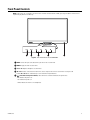
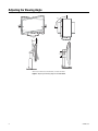
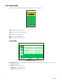
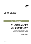
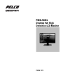
PMCL524BL
Desktop Full High
Definition LCD Monitor
C3964M (12/13)
2
C3964M (12/13)
Contents
Important Safety Instructions . . . . . . . . . . . . . . . . . . . . . . . . . . . . . . . . . . . . . . . . . . . . . . . . . . . . . . . . . . . . . . . . . . . . . . . . . . . . . . . . . . . . . . . . . . . . 5
Important Notices . . . . . . . . . . . . . . . . . . . . . . . . . . . . . . . . . . . . . . . . . . . . . . . . . . . . . . . . . . . . . . . . . . . . . . . . . . . . . . . . . . . . . . . . . . . . . . . . . . . . . 6
Regulatory Notices . . . . . . . . . . . . . . . . . . . . . . . . . . . . . . . . . . . . . . . . . . . . . . . . . . . . . . . . . . . . . . . . . . . . . . . . . . . . . . . . . . . . . . . . . . . . . . . . 6
Legal Notice . . . . . . . . . . . . . . . . . . . . . . . . . . . . . . . . . . . . . . . . . . . . . . . . . . . . . . . . . . . . . . . . . . . . . . . . . . . . . . . . . . . . . . . . . . . . . . . . . . . . . 6
Video Quality Caution . . . . . . . . . . . . . . . . . . . . . . . . . . . . . . . . . . . . . . . . . . . . . . . . . . . . . . . . . . . . . . . . . . . . . . . . . . . . . . . . . . . . . . . . . . . . . . 6
Open Source Software . . . . . . . . . . . . . . . . . . . . . . . . . . . . . . . . . . . . . . . . . . . . . . . . . . . . . . . . . . . . . . . . . . . . . . . . . . . . . . . . . . . . . . . . . . . . . 7
CCC Power Cord Statement . . . . . . . . . . . . . . . . . . . . . . . . . . . . . . . . . . . . . . . . . . . . . . . . . . . . . . . . . . . . . . . . . . . . . . . . . . . . . . . . . . . . . . . . . 7
Warranty . . . . . . . . . . . . . . . . . . . . . . . . . . . . . . . . . . . . . . . . . . . . . . . . . . . . . . . . . . . . . . . . . . . . . . . . . . . . . . . . . . . . . . . . . . . . . . . . . . . . . . . . 7
Network Topology Statement. . . . . . . . . . . . . . . . . . . . . . . . . . . . . . . . . . . . . . . . . . . . . . . . . . . . . . . . . . . . . . . . . . . . . . . . . . . . . . . . . . . . . . . . 7
Legal Notice (Audio Notice) . . . . . . . . . . . . . . . . . . . . . . . . . . . . . . . . . . . . . . . . . . . . . . . . . . . . . . . . . . . . . . . . . . . . . . . . . . . . . . . . . . . . . . . . . 7
Description. . . . . . . . . . . . . . . . . . . . . . . . . . . . . . . . . . . . . . . . . . . . . . . . . . . . . . . . . . . . . . . . . . . . . . . . . . . . . . . . . . . . . . . . . . . . . . . . . . . . . . . . . . . 8
Models . . . . . . . . . . . . . . . . . . . . . . . . . . . . . . . . . . . . . . . . . . . . . . . . . . . . . . . . . . . . . . . . . . . . . . . . . . . . . . . . . . . . . . . . . . . . . . . . . . . . . . . . . 8
Recommended Mounts. . . . . . . . . . . . . . . . . . . . . . . . . . . . . . . . . . . . . . . . . . . . . . . . . . . . . . . . . . . . . . . . . . . . . . . . . . . . . . . . . . . . . . . . . . . . . 8
Package Contents . . . . . . . . . . . . . . . . . . . . . . . . . . . . . . . . . . . . . . . . . . . . . . . . . . . . . . . . . . . . . . . . . . . . . . . . . . . . . . . . . . . . . . . . . . . . . . . . . 9
Installation . . . . . . . . . . . . . . . . . . . . . . . . . . . . . . . . . . . . . . . . . . . . . . . . . . . . . . . . . . . . . . . . . . . . . . . . . . . . . . . . . . . . . . . . . . . . . . . . . . . . . . . . . . 10
Removing the Stand for Wall Mounting. . . . . . . . . . . . . . . . . . . . . . . . . . . . . . . . . . . . . . . . . . . . . . . . . . . . . . . . . . . . . . . . . . . . . . . . . . . . . . . 10
Installing a VESA Standard Wall Mount Kit. . . . . . . . . . . . . . . . . . . . . . . . . . . . . . . . . . . . . . . . . . . . . . . . . . . . . . . . . . . . . . . . . . . . . . . . . . . . 11
Rear Panel Connectors. . . . . . . . . . . . . . . . . . . . . . . . . . . . . . . . . . . . . . . . . . . . . . . . . . . . . . . . . . . . . . . . . . . . . . . . . . . . . . . . . . . . . . . . . . . . . . . . . 12
Front Panel Controls. . . . . . . . . . . . . . . . . . . . . . . . . . . . . . . . . . . . . . . . . . . . . . . . . . . . . . . . . . . . . . . . . . . . . . . . . . . . . . . . . . . . . . . . . . . . . . . . . . . 13
Adjusting the Viewing Angle. . . . . . . . . . . . . . . . . . . . . . . . . . . . . . . . . . . . . . . . . . . . . . . . . . . . . . . . . . . . . . . . . . . . . . . . . . . . . . . . . . . . . . . . . . . . 14
On-Screen Display (OSD) Functions. . . . . . . . . . . . . . . . . . . . . . . . . . . . . . . . . . . . . . . . . . . . . . . . . . . . . . . . . . . . . . . . . . . . . . . . . . . . . . . . . . . . . . . 15
OSD Menu Structure. . . . . . . . . . . . . . . . . . . . . . . . . . . . . . . . . . . . . . . . . . . . . . . . . . . . . . . . . . . . . . . . . . . . . . . . . . . . . . . . . . . . . . . . . . . . . . 15
Input Source Menu . . . . . . . . . . . . . . . . . . . . . . . . . . . . . . . . . . . . . . . . . . . . . . . . . . . . . . . . . . . . . . . . . . . . . . . . . . . . . . . . . . . . . . . . . . . . . . . 16
Picture Menu . . . . . . . . . . . . . . . . . . . . . . . . . . . . . . . . . . . . . . . . . . . . . . . . . . . . . . . . . . . . . . . . . . . . . . . . . . . . . . . . . . . . . . . . . . . . . . . 16
Sound Menu. . . . . . . . . . . . . . . . . . . . . . . . . . . . . . . . . . . . . . . . . . . . . . . . . . . . . . . . . . . . . . . . . . . . . . . . . . . . . . . . . . . . . . . . . . . . . . . . 17
Option Menu . . . . . . . . . . . . . . . . . . . . . . . . . . . . . . . . . . . . . . . . . . . . . . . . . . . . . . . . . . . . . . . . . . . . . . . . . . . . . . . . . . . . . . . . . . . . . . . 17
Setting Menu . . . . . . . . . . . . . . . . . . . . . . . . . . . . . . . . . . . . . . . . . . . . . . . . . . . . . . . . . . . . . . . . . . . . . . . . . . . . . . . . . . . . . . . . . . . . . . . 18
VGA, DVI, HDMI, and PIP Mode Tables. . . . . . . . . . . . . . . . . . . . . . . . . . . . . . . . . . . . . . . . . . . . . . . . . . . . . . . . . . . . . . . . . . . . . . . . . . . . . . . . . . . . 19
Maintenance . . . . . . . . . . . . . . . . . . . . . . . . . . . . . . . . . . . . . . . . . . . . . . . . . . . . . . . . . . . . . . . . . . . . . . . . . . . . . . . . . . . . . . . . . . . . . . . . . . . . . . . . 20
Troubleshooting . . . . . . . . . . . . . . . . . . . . . . . . . . . . . . . . . . . . . . . . . . . . . . . . . . . . . . . . . . . . . . . . . . . . . . . . . . . . . . . . . . . . . . . . . . . . . . . . . 20
Specifications . . . . . . . . . . . . . . . . . . . . . . . . . . . . . . . . . . . . . . . . . . . . . . . . . . . . . . . . . . . . . . . . . . . . . . . . . . . . . . . . . . . . . . . . . . . . . . . . . . . . . . . 21
C3964M (12/13)
3
List of Illustrations
1
2
3
4
5
6
7
8
9
10
11
12
13
4
Package Contents . . . . . . . . . . . . . . . . . . . . . . . . . . . . . . . . . . . . . . . . . . . . . . . . . . . . . . . . . . . . . . . . . . . . . . . . . . . . . . . . . . . . . . . . . . . . . . . . . 9
Unscrewing the Stand Screws . . . . . . . . . . . . . . . . . . . . . . . . . . . . . . . . . . . . . . . . . . . . . . . . . . . . . . . . . . . . . . . . . . . . . . . . . . . . . . . . . . . . . . 10
Detaching the Stand . . . . . . . . . . . . . . . . . . . . . . . . . . . . . . . . . . . . . . . . . . . . . . . . . . . . . . . . . . . . . . . . . . . . . . . . . . . . . . . . . . . . . . . . . . . . . . 10
Wall Mount Kit Installation Holes . . . . . . . . . . . . . . . . . . . . . . . . . . . . . . . . . . . . . . . . . . . . . . . . . . . . . . . . . . . . . . . . . . . . . . . . . . . . . . . . . . . 11
Rear Panel Connectors of the PMCL524BL. . . . . . . . . . . . . . . . . . . . . . . . . . . . . . . . . . . . . . . . . . . . . . . . . . . . . . . . . . . . . . . . . . . . . . . . . . . . . 12
Front Panel Controls for the PMCL524BL . . . . . . . . . . . . . . . . . . . . . . . . . . . . . . . . . . . . . . . . . . . . . . . . . . . . . . . . . . . . . . . . . . . . . . . . . . . . . . 13
Adjusting the Viewing Angle for the PMCL524BL . . . . . . . . . . . . . . . . . . . . . . . . . . . . . . . . . . . . . . . . . . . . . . . . . . . . . . . . . . . . . . . . . . . . . . . 14
OSD Mode Menus . . . . . . . . . . . . . . . . . . . . . . . . . . . . . . . . . . . . . . . . . . . . . . . . . . . . . . . . . . . . . . . . . . . . . . . . . . . . . . . . . . . . . . . . . . . . . . . 15
Input Source Menu . . . . . . . . . . . . . . . . . . . . . . . . . . . . . . . . . . . . . . . . . . . . . . . . . . . . . . . . . . . . . . . . . . . . . . . . . . . . . . . . . . . . . . . . . . . . . . . 16
Picture Menu. . . . . . . . . . . . . . . . . . . . . . . . . . . . . . . . . . . . . . . . . . . . . . . . . . . . . . . . . . . . . . . . . . . . . . . . . . . . . . . . . . . . . . . . . . . . . . . . . . . . 16
Sound Menu . . . . . . . . . . . . . . . . . . . . . . . . . . . . . . . . . . . . . . . . . . . . . . . . . . . . . . . . . . . . . . . . . . . . . . . . . . . . . . . . . . . . . . . . . . . . . . . . . . . . 17
Option Menu . . . . . . . . . . . . . . . . . . . . . . . . . . . . . . . . . . . . . . . . . . . . . . . . . . . . . . . . . . . . . . . . . . . . . . . . . . . . . . . . . . . . . . . . . . . . . . . . . . . . 17
Setting Menu . . . . . . . . . . . . . . . . . . . . . . . . . . . . . . . . . . . . . . . . . . . . . . . . . . . . . . . . . . . . . . . . . . . . . . . . . . . . . . . . . . . . . . . . . . . . . . . . . . . 18
C3964M (12/13)
Important Safety Instructions
1. Read these instructions.
2. Keep these instructions.
3. Heed all warnings.
4. Follow all instructions.
5. Clean only with dry cloth.
6. Do not block any ventilation openings. Install in accordance with the manufacturer’s instructions.
7. Do not install near any heat sources such as radiators, heat registers, stoves, or other apparatus (including amplifiers) that produce heat.
8. Do not defeat the safety purpose of the polarized or grounding-type plug. A polarized plug has two blades with one blade wider than the
other. A grounding plug has two blades and a third grounding prong. The wide blade or the third prong are provided for your safety. If the
provided plug does not fit into your outlet, consult an electrician for replacement of the obsolete outlet.
9. Protect the power cord from being walked on or pinched particularly at plugs, convenience receptacles, and the points where they exit from
the apparatus.
10. Only use attachments/accessories specified by the manufacturer.
11. Only use with the cart, stand, tripod, bracket, or table specified by the manufacturer, or sold with the apparatus. When a cart is used, use
caution when moving the cart/apparatus combination to avoid injury from tip-over.
12. Refer all servicing to qualified service personnel. Servicing is required when the apparatus has been damaged in any way, such as power
supply cord or plug is damaged, liquid has been spilled or objects have fallen into the apparatus, the apparatus has been exposed to rain or
moisture, does not operate normally, or has been dropped.
13. WARNING: To reduce the risk of fire or electric shock, do not expose this apparatus to rain or moisture.
14. Installation should be done only by qualified personnel and conform to all local codes.
15. Unless this unit is specifically marked as NEMA Type 3, 3R, 3S, 4, 4X, 6, or 6P enclosure, it is designed for indoor use only and it must not
be installed where exposed to rain and moisture.
16. Only use installation methods and materials capable of supporting four times the maximum specified load.
17. An all-pole mains switch with a contact separation of at least 3 mm in each pole shall be incorporated in the electrical installation of the
building.
18. A readily accessible disconnect device shall be incorporated in the building installation wiring.
19. The socket-outlet shall be installed near the equipment and shall be easily accessible.
CAUTION: These servicing instructions are for use by qualified service personnel only. To reduce the risk of electric shock do not perform any
servicing other that contained in the operating instructions unless you are qualified to do so.
CAUTION: Danger of explosion if battery is incorrectly replaced. Replace only with the same or equivalent type. Dispose of used batteries
according to the instructions provided by the battery manufacturer.
Only use replacement parts recommended by Pelco.
The product and/or manual may bear the following marks:
This symbol indicates that dangerous voltage constituting a risk of electric shock is present
within this unit.
This symbol indicates that there are important operating and maintenance instructions in
the literature accompanying this unit.
CAUTION:
RISK OF ELECTRIC SHOCK.
DO NOT OPEN.
WARNING: This product is sensitive to Electrostatic Discharge (ESD). To avoid ESD damage to this product, use ESD safe
practices during installation. Before touching, adjusting or handling this product, correctly attach an ESD wrist strap to your wrist
and appropriately discharge your body and tools. For more information about ESD control and safe handling practices of
electronics, please refer to ANSI/ESD S20.20-1999 or contact the Electrostatic Discharge Association (www.esda.org).
C3964M (12/13)
5
Important Notices
REGULATORY NOTICES
This device complies with Part 15 of the FCC Rules. Operation is subject to the following two conditions: (1) this device may not cause harmful
interference, and (2) this device must accept any interference received, including interference that may cause undesired operation.
RADIO AND TELEVISION INTERFERENCE
This equipment has been tested and found to comply with the limits of a Class A digital device, pursuant to Part 15 of the FCC rules. These limits
are designed to provide reasonable protection against harmful interference when the equipment is operated in a commercial environment.
This equipment generates, uses, and can radiate radio frequency energy and, if not installed and used in accordance with the instruction manual,
may cause harmful interference to radio communications. Operation of this equipment in a residential area is likely to cause harmful interference
in which case the user will be required to correct the interference at his own expense.
Changes and Modifications not expressly approved by the manufacturer or registrant of this equipment can void your authority to operate this
equipment under Federal Communications Commission’s rules.
To maintain compliance with FCC regulations shielded cables must be used with this equipment. Operation with non-approved equipment or
unshielded cables is likely to result in interference to radio and television reception.
This Class A digital apparatus complies with Canadian ICES-003.
Cet appareil numérique de la classe A est conforme à la norme NMB-003 du Canada.
KCC CERTIFICATION
ESD WARNING
WARNING: This product is sensitive to Electrostatic Discharge (ESD). To avoid ESD damage to this product, use ESD safe
practices during installation. Before touching, adjusting or handling this product, correctly attach an ESD wrist strap to your wrist
and appropriately discharge your body and tools. For more information about ESD control and safe handling practices of
electronics, please refer to ANSI/ESD S20.20-1999 or contact the Electrostatic Discharge Association (www.esda.org).
LEGAL NOTICE
SOME PELCO EQUIPMENT CONTAINS, AND THE SOFTWARE ENABLES, AUDIO/VISUAL AND RECORDING CAPABILITIES, THE IMPROPER USE OF
WHICH MAY SUBJECT YOU TO CIVIL AND CRIMINAL PENALTIES. APPLICABLE LAWS REGARDING THE USE OF SUCH CAPABILITIES VARY
BETWEEN JURISDICTIONS AND MAY REQUIRE, AMONG OTHER THINGS, EXPRESS WRITTEN CONSENT FROM RECORDED SUBJECTS. YOU
ARE SOLELY RESPONSIBLE FOR INSURING STRICT COMPLIANCE WITH SUCH LAWS AND FOR STRICT ADHERENCE TO ANY/ALL RIGHTS OF
PRIVACY AND PERSONALTY. USE OF THIS EQUIPMENT AND/OR SOFTWARE FOR ILLEGAL SURVEILLANCE OR MONITORING SHALL BE DEEMED
UNAUTHORIZED USE IN VIOLATION OF THE END USER SOFTWARE AGREEMENT AND RESULT IN THE IMMEDIATE TERMINATION OF YOUR
LICENSE RIGHTS THEREUNDER.
VIDEO QUALITY CAUTION
FRAME RATE NOTICE REGARDING USER SELECTED OPTIONS
Pelco systems are capable of providing high quality video for both live viewing and playback. However, the systems can be used in lower quality
modes, which can degrade picture quality, to allow for a slower rate of data transfer and to reduce the amount of video data stored. The picture
quality can be degraded by either lowering the resolution, reducing the picture rate, or both. A picture degraded by having a reduced resolution
may result in an image that is less clear or even indiscernible. A picture degraded by reducing the picture rate has fewer frames per second,
which can result in images that appear to jump or move more quickly than normal during playback. Lower frame rates may result in a key event
not being recorded by the system.
6
C3964M (12/13)
Judgment as to the suitability of the products for users' purposes is solely the users' responsibility. Users shall determine the suitability of the
products for their own intended application, picture rate and picture quality. In the event users intend to use the video for evidentiary purposes in
a judicial proceeding or otherwise, users should consult with their attorney regarding any particular requirements for such use.
OPEN SOURCE SOFTWARE
This product includes certain open source or other software originated from third parties that is subject to the GNU General Public License (GPL),
GNU Library/Lesser General Public License (LGPL) and different and/or additional copyright licenses, disclaimers, and notices.
The exact terms of GPL, LGPL, and some other licenses are provided to you with this product. Please refer to the exact terms of the GPL and LGPL
at http://www.fsf.org (Free Software Foundation) or http://www.opensource.org (Open Source Initiative) regarding your rights under said license.
You may obtain a complete corresponding machine-readable copy of the source code of such software under the GPL or LGPL by sending your
request to [email protected]; the subject line should read Source Code Request. You will then receive an email with a link for you to
download the source code.
This offer is valid for a period of three (3) years from the date of the distribution of this product by Pelco.
CCC POWER CORD STATEMENT
Models shipped to China do not include power cords.
NOTE: A CCC approved power cord must be used to power the equipment when used in China.
WARRANTY
For information about Pelco's product warranty and thereto related information, refer to www.pelco.com/warranty.
NETWORK TOPOLOGY STATEMENT
IMPORTANT NOTE. PLEASE READ. The network implementation is shown as a general representation only and is not intended to show a
detailed network topology. Your actual network will differ, requiring changes or perhaps additional network equipment to accommodate the
system as illustrated. Please contact your local Pelco representative to discuss your specific requirements.
LEGAL NOTICE (AUDIO NOTICE)
NOTE: Improper use of audio/visual recording equipment may subject you to civil and criminal penalties. Applicable laws regarding the use of
such capabilities vary between jurisdictions and may require, among other things, express written consent from the recorded subjects. You are
solely responsible for insuring strict compliance with such laws and for strict adherence to any/all right of privacy and personality.
C3964M (12/13)
7
Description
Pelco’s PMCL500 Series small, full high-definition (FHD) monitors deliver 1920 x 1080 native resolution with high performance and the truest
color reproduction available. These displays combine the latest technologies into a perfect compliment to your investment in megapixel imaging
and performance. These monitors are specifically engineered to exceed the demands of surveillance operators.
NOTE: When the PC goes into sleep mode, the monitor turns off. Activating the PC (either by moving the mouse, hitting a keyboard key, or
pressing the power button) does not activate the monitor. You must press the power button for the video to resume.
MODELS
PMCL524BL
24-inch LCD monitor (610 mm)
RECOMMENDED MOUNTS
PMCL-WM
8
Wall mount
PMCL-WMT
Tilt/swivel wall mount
PMCL-CM
Ceiling mount
PMCL-CMP
Ceiling mount with pole
PMCL-WM1A
Tilt/swivel single-arm wall mount
C3964M (12/13)
PACKAGE CONTENTS
Figure 1. Package Contents
ì 24-inch FHD Monitor (1 ea.)
ó DVI Cable (1 ea.)
î Power Adapter (1 ea.)
r VGA Cable with 15-Pin D-Sub Connection (1 ea.)
ï USA Standard Power Cord (1 ea.)
s Quick Start Guide (1 ea.)
ñ European Standard Power Cord (1 ea.)
t Operation Manual Resource Disc (1 ea.)
NOTE: Consider keeping the box and packaging in storage for use in the future when you may need to transport the monitor. The fitted foam
packing is ideal for protecting the monitor during transport.
C3964M (12/13)
9
Installation
REMOVING THE STAND FOR WALL MOUNTING
1. Turn off the monitor and the power before disconnecting the power cable.
2. Turn off the computer before disconnecting the monitor signal cable.
3. Clear an open area on a flat workspace, such as your desk.
4. To protect the monitor and screen, place a soft towel between the screen and the desk to create a padded surface.
5. Lay the screen face down on the towel and unscrew the four screws that attach the stand to the monitor (refer to Figure 2).
STAND SCREWS
Figure 2. Unscrewing the Stand Screws
6. Detach the stand from the monitor (refer to Figure 3).
7. Store the screws and the stand in a safe place for future use.
Figure 3. Detaching the Stand
10
C3964M (12/13)
INSTALLING A VESA STANDARD WALL MOUNT KIT
You can install the monitor on a VESA® standard 100 mm x 100 mm (3.94 in x 3.94 in) for PMCL524BL wall mount kit using the four wall mount kit
installation holes on the rear panel of the monitor.
100 mm
(3.94 in)
100 mm
(3.94 in)
Figure 4. Wall Mount Kit Installation Holes
NOTE: The mounting interface must comply with the UL1678 standard in North America. The mounting should be strong enough to bear the
weight of the monitor (7.2 kg/15.9 lb) without the stand.
C3964M (12/13)
11
Rear Panel Connectors
Figure 5. Rear Panel Connectors of the PMCL524BL
ì Kensington Security Slot: Attaches a Kensington-type security lock to prevent the monitor from theft.
î Cable Retainer: Confines the signal cables to keep the desktop tidy.
ï DC Power: Connects power to the unit from the supplied 12 VDC power adapter.
ñ HDMI: Provides connection to digital video signals from a computer or any Pelco device with HDMI output.
ó DVI: Provides connection to digital video signals from a computer or any Pelco device with DVI output.
r VGA: Provides connection to VGA output of a computer or any Pelco device with VGA output.
s RS-232: This port is not for customer use; it is intended for factory service use only.
t S-Video: Provides connection of S-Video signals from external sources.
u Video: BNC input connections from DVD players or time-lapse VCRs.
~í Audio-In: Provides audio connection from a PC or recording device. The stereo mini jack is to be used with the VGA input.
12
C3964M (12/13)
Front Panel Controls
NOTE: If the PC goes into “sleep mode,” the monitor turns off. When connected via DVI or HDMI, press the power button on the monitor to
regain the display after the PC “wakes up.”
INPUT
INPUT
MENU
MENU
Figure 6. Front Panel Controls for the PMCL524BL
ì INPUT: Selects the input source and confirms your choice in an on-screen menu.
î MENU: Displays the main on-screen menu.
ï
Tand S: Navigates through the on-screen menus.
ñ W and X: Increases or decreases the volume. Also selects or adjusts items in the on-screen menu. You can press and
hold the W and X buttons simultaneously to lock or unlock the front panel buttons.
ó
(power button and power indicator): Turns the monitor on and off and indicates the power status.
• Off indicates the power is off.
• On indicates the power is on.
• Amber indicates the monitor is in standby mode.
C3964M (12/13)
13
Adjusting the Viewing Angle
90º
45º
45º
20º
5º
5.19
(13.0)
NOTE: VALUES IN PARENTHESES ARE CENTIMETERS; ALL OTHERS ARE INCHES.
Figure 7. Adjusting the Viewing Angle for the PMCL524BL
14
C3964M (12/13)
On-Screen Display (OSD) Functions
To access the menus, use the MENU button on the monitor front panel:
1. Press the MENU button to access the main menu.
2. Use the up and down arrow buttons (Tand S) to highlight a selection.
3. Press the INPUT button or the right arrow button (X) to select an item.
4. Use the up and down arrow buttons (Tand S) to adjust the selected menu settings.
OSD MENU STRUCTURE
Picture Menu
Main Menu
Picture
Sound
Option
Setting
Color Temperature Menu
< Color Temperature >
0 llllllllll 100
Contrast
0 llllllllll 100
Brightness
0 llllllllll 100
Color
0 llllllllll 100
Tint
0 llllllllll 10
Sharpness
0 llllllllll 5
Backlight
Cool
Normal
< User >
User Menu
R
G
B
0 llllllllll 255
0 llllllllll 255
0 llllllllll 255
Mute Menu
ON
OFF
Sound Menu
Volume
0 llllllllll 16
< Mute >
< Audio Source >
Audio Source Menu
Line In
HDMI
Option Menu
Aspect Ratio Menu
< Aspect Ratio >
< PIP >
< Source >
Auto Adjustment
Clock Frequency 0 llllllllll 32
Phase
0 llllllllll 32
H.Position
0 llllllllll 100
V.Position
0 llllllllll 100
< Blue Screen >
Full
Original
PIP Menu
ON/OFF
< Main Input >
< Sub Input >
< PIP Size >
PIP Position
PIP Swap
Source Menu
Video
S-Video
VGA
DVI
HDMI
Blue Screen Menu
Main Input Menu
Video
S-Video
DVI
HDMI
Sub Input Menu
Video
S-Video
DVI
HDMI
PIP Size Menu
Small
Medium
Large
ON
OFF
Setting Menu
Language
Overscan
Power Save
ISM
Auto Adjustment
Reset All Setting
Language Menu
ON/OFF
ON/OFF
ON/OFF
ON/OFF
English
Russian
German
Portuguese
French
Chinese (Simplified)
Spanish
Italian
Figure 8. OSD Mode Menus
C3964M (12/13)
15
INPUT SOURCE MENU
Access the Input Source menu by pressing the INPUT button on the monitor or on the remote control.
Input Source
Video
S-Video
VGA
DVI
HDMI
Enter
:Enter
Exit :Exit
Figure 9. Input Source Menu
Video: Selects Video as the input image source.
S-Video: Selects S-Video as the input image source.
VGA: Selects VGA as the input image source.
DVI: Selects DVI as the input image source.
HDMI: Selects HDMI as the input image source.
PICTURE MENU
Picture
Color Temperature
Contrast
Brightness
Color
Tint
Sharpness
Backlight
:Move
:Enter
Normal
50
50
50
0
0
5
:Exit
Figure 10. Picture Menu
Color Temperature: Changes the color temperature of the video screen image. Select Cool, Normal, or User. If you select User, you can select
from the following calibrations:
16
•
R (Red): Adjusts gain for red (0 to 255).
•
G (Green): Adjusts gain for green (0 to 255).
•
B (Blue): Adjusts gain for blue (0 to 255).
C3964M (12/13)
Contrast: Adjusts the black level of the video screen image (0 to 100).
Brightness: Adjusts white level of the video screen image (0 to 100).
Color: (Video, S-Video and HDMI only) Adjusts the color intensity of the video screen image (0 to 100).
Tint: (Video, S-Video and HDMI only) Adjusts the image color tint of the video screen image (0 to 100).
Sharpness: Adjusts the picture softer or sharper (0 to 10).
Backlight: Adjusts the backlight intensity of the LCD screen (0 to 5).
SOUND MENU
Sound
Volume
Mute
Audio Source
:Move
8
OFF
Line In
:Enter
:Exit
Figure 11. Sound Menu
Volume: Adjusts the audio volume (0 to 16).
Mute: Turns off the audio function temporarily; select ON or OFF.
Audio Source: Selects the audio input source. You can select an audio input source from Line In (from the Audio-In jack) or HDMI (from the
HDMI jack, only available when HDMI signal is detected).
OPTION MENU
Option
Aspect Ratio
PIP
Source
Auto Adjustment
Clock Frequency
Phase
H.Position
V.Position
Blue Screen
:Move
:Enter
Full
HDMI
OFF
:Exit
Figure 12. Option Menu
C3964M (12/13)
17
Aspect Ratio: Displays the input image in either its original or full aspect ratio. Select Original or Full. When Full is selected, the input image is
displayed across the entire screen.
PIP: (DVI,HDMI,Video and S-Video only) Accesses the PIP settings. Select one of the following options:
•
ON/OFF: Turns the PIP feature on and off. Select OFF or ON.
•
Main Input: Changes the PIP video input option for the main picture. Select Video, S-Video, DVI, or HDMI.
•
Sub Input: Changes the PIP video input option for the PIP view window. Select Video, S-Video, DVI, or HDMI.
•
PIP Size: Adjusts the size of the PIP view window. Select Small, Medium, or Large.
•
PIP Position: Press the 3, 4, 5 and 6 buttons to change the position of the PIP view window.
•
PIP Swap: Exchanges the main picture with PIP.
Source: Changes the video input option. Select Video, S-Video, VGA, DVI, or HDMI.
Auto Adjustment: (VGA only) Adjusts the screen size, horizontal position, vertical position, clock frequency, and phase automatically.
Clock Frequency: (VGA only) Adjusts the horizontal size of the screen image (0 to 32).
Phase: (VGA only) Adjusts image distortion that appears as horizontal noise on the screen (0 to 32).
H.Position: (VGA only) Adjusts the horizontal position (0 to 100).
V.Position: (VGA only) Adjusts the vertical position (0 to 100).
Blue Screen: Turns the blue screen function on or off. If turned on, a blue screen will be displayed when no input signal is detected by the
monitor. Select OFF or ON.
SETTING MENU
Setting
Language
Overscan
Power Save
ISM
Auto Adjustment
Reset All Setting
:Move
:Enter
English
OFF
OFF
:Exit
Figure 13. Setting Menu
Language: Selects the OSD language: English, Russian, German, Portuguese, French, Chinese (simplified), Spanish, or Italian.
Overscan: (HDMI only) Turns on or off the overscan function when displaying an HDMI input image. Select OFF or ON.
Power Save: If turned on, the monitor will go to power management mode when the PC input signal is lost, and it will enter power management
mode when no video input signal can be detected three consecutive times. Select OFF or ON.
ISM (Image Sticking Minimization): If turned on, the monitor automatically displays swift moving patterns to prevent the formation of image
retention on the screen. Select OFF or ON.
Auto Adjustment: Turns the Auto Adjustment function on or off. Once turned on, the monitor will automatically optimize the image by adjusting
the vertical position, horizontal position, clock frequency, and phase when the input signal timing is changed. Select OFF or ON.
Reset All Setting: If activated, all OSD settings (except the Language setting) will be restored to the factory settings.
18
C3964M (12/13)
VGA, DVI, HDMI, and PIP Mode Tables
NOTE: Not all resolutions generated by your video source are available on the monitor.
Table A. HDMI Mode
Mode
Resolution
Vertical Frequency (Hz)
EDTV 480i
720 x 480
30
EDTV 576i
720 x 576
25
SDTV 480p
720 x 480
60
SDTV 576p
720 x 576
60
HDTV 720p
1280 x 720
50/60
HDTV 1080i
1920 x 1080
30/25
HDTV 1080p
1920 x 1080
60/50
Table B. VGA/DVI Mode
Mode
Resolution
Vertical Frequency (Hz)
VGA
720 x 400
70
640 x 480
60/72/75 (50/60 not available
for DVI and HDMI inputs in
CVT format)
SVGA
800 x 600
50/60/72/75
XGA
1024 x 768
50/60/75
WXGA
1366 x 768
60
UXGA
1600 x 1200
60
HD
1920 x 1080
60
Table C. PIP Mode
SUB
MAIN
Video
Video
S-Video
VGA
DVI
HDMI
°
°
•
•
•
•
°
°
S-Video
°
VGA
°
°
DVI
•
•
°
HDMI
•
•
°
°
°
°
•PIP
°No PIP
NOTE: PIP mode is not supported in 1600 x 1200, UXGA mode.
C3964M (12/13)
19
Maintenance
Periodically, you might need to clean the monitor to maintain optimum viewing performance. Be sure to observe the following cleaning
instructions to avoid damage to the monitor:
•
Gently wipe your screen with a clean camel hair brush or a soft, clean, lint-free cloth.
•
Gently apply pressure to the screen surface to clean the display.
•
Do not spray any liquid directly on the screen or the LCD monitor casing.
•
Chemical cleaners can damage the screen and the LCD monitor casing.
The 32-inch monitor can be operated using the remote control, which requires two AAA batteries. Be sure to observe the following practices
when disposing of batteries:
•
Remove dead batteries immediately to prevent battery acid from leaking into the battery compartment.
•
Remove the batteries if you do not intend to use the remote control for a long period of time.
•
Dispose of batteries in a designated disposal area.
•
Do not throw batteries into a fire.
•
Do not mix battery types.
TROUBLESHOOTING
If the following instructions fail to solve your problem, contact Pelco Product Support at 1-800-289-9100 (USA and Canada) or +1-559-292-1981
(international) for assistance. Be sure to have the serial number available when calling.
Do not try to repair the unit yourself. Opening it immediately voids the warranty. Leave maintenance and repairs to qualified technical personnel
only.
WARNING: To reduce the risk of electrical shock, do not remove the cover or back of the monitor. There are no user-serviceable parts
inside.
20
Problem
Possible Causes
Suggested Resolution
Poor picture quality.
Faulty system or cable connections.
Make adjustments on the front panel control.
Inspect all system connections and cables.
Intermittent loss of video in PIP and main
video.
In NTSC/PAL, when using PIP, cycling
through cameras (with one or more cameras
out of operation) causes the monitor to auto
adjust and locate the signal.
Check your input devices. If there is a
problem with a camera from another input
device, such as no power signal or bad video,
disconnect and reconnect the camera or
device.
C3964M (12/13)
Specifications
GENERAL
Viewing Area
531 mm x 299 mm (20.9 in x 11.8 in)
Number of Pixels
1920 (H) x 1080 (V)
Pixel Pitch
0.277 mm x 0.277 mm (0.011 in x 0.011 in)
Brightness
250 cd/m2 (typical)
Contrast Ratio
1000:1
Backlight Type
LED
Refresh Rate
60 Hz
Viewing Angle (H/V)
170°/160°
Response Time
5 ms
Native Resolution
1920 x 1080 at 60 Hz
Optimum Resolution (VGA Mode)
VGA
SVGA
XGA
WXGA
SDTV (480i/480p/576i/576p)
HDTV (720p/1080i/1080p)
720 x 400 at 70 Hz
640 x 480 at 60/72/75 Hz
(50/60 Hz not available for DVI and HDMI inputs in CVT format)
800 x 600 at 50/60/72/75 Hz
1024 x 768 at 50/60/75 Hz
1360 x 768/1366 x 768 at 60 Hz
1920 x 1080 at 60 Hz
720 x 480 at 60 Hz
720 x 576 at 50 Hz
1280 x 720 at 50/60 Hz
1920 x 1080 at 50/60 Hz
1920 x 1080i at 50/60 Hz
Panel Aspect Ratio
16:9
Video Formats
480p, 576p, 720p, 1080i, 1080p
Panel Life
30,000 hours
Display Colors
16.7 million
PIP (Picture-In-Picture)
Selectable, sizable, moveable, swappable
Speakers
2, internal (3W)
Front Panel Controls
MENU, INPUT, menu navigation, volume, power button, power indicator
Indicators
LED (power on/off)
VESA Mounting Compliance
100 mm x 100 mm (3.94 in x 3.94 in)
ELECTRICAL
Power Consumption
<33 W
Input Voltage
100 to 240 VAC, 50/60 Hz
Input Interfaces
Video Input
Audio
1 Video (BNC); 1 S-Video; 1 VGA; 1 DVI; 1 HDMI
PC audio jack
Horizontal Frequency
15 kHz to 75 kHz
Vertical Frequency
25 Hz to 75 Hz
Sync Format
NTSC/PAL
ENVIRONMENTAL
Operating Temperature
0°C to 40°C (32°F to 104°F)
Storage Temperature
–20°C to 60°C (–4°F to 140°F)
Operating Humidity
20% to 80%, noncondensing
Storage Humidity
10% to 90%, noncondensing
C3964M (12/13)
21
PHYSICAL
Dimensions (with stand)
213 mm x 569 mm x 429 mm (8.4 in x 22.4 in x 16.9 in)
Unit Weight
7.2 kg (15.9 lb)
Shipping Weight
11 kg (24 lb)
NOTE: The PMCL524BL is a VESA-compliant monitor equipped with a 100 mm x 100 mm mounting hole pattern.
22
C3964M (12/13)
This equipment contains electrical or electronic components that must be recycled properly to comply with Directive 2002/96/EC of the European Union
regarding the disposal of waste electrical and electronic equipment (WEEE). Contact your local dealer for procedures for recycling this equipment.
REVISION HISTORY
Manual #
C3964M
Date
12/13
Comments
Original version.
Pelco, the Pelco logo, and other trademarks associated with Pelco products referred to in this publication are trademarks of Pelco, Inc. or its affiliates.
ONVIF and the ONVIF logo are trademarks of ONVIF Inc. All other product names and services are the property of their respective companies. All rights reserved.
Product specifications and availability are subject to change without notice.
© Copyright 2014, Pelco, Inc.
Pelco by Schneider Electric 3500 Pelco Way Clovis, California 93612-5699 United States
USA & Canada Tel (800) 289-9100 Fax (800) 289-9150
International Tel +1 (559) 292-1981 Fax +1 (559) 348-1120
www.pelco.com www.pelco.com/community