1
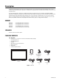
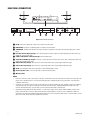
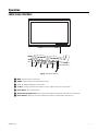
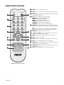
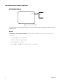
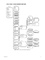
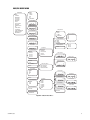
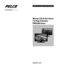
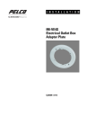
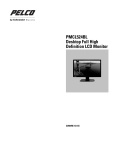
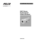
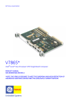
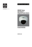
INSTALLATION/OPERATION
500 Series Flat Panel
LCD Monitor
C2937M-D (1/09)
Contents
Important Safety Instructions . . . . . . . . . . . . . . . . . . . . . . . . . . . . . . . . . . . . . . . . . . . . . . . . . . . . . . . . . . . . . . . . . . . . . . . . . . . . . . . . . . . . . . . . . . . . 4
Regulatory Notices . . . . . . . . . . . . . . . . . . . . . . . . . . . . . . . . . . . . . . . . . . . . . . . . . . . . . . . . . . . . . . . . . . . . . . . . . . . . . . . . . . . . . . . . . . . . . . . . . . . . 5
Description. . . . . . . . . . . . . . . . . . . . . . . . . . . . . . . . . . . . . . . . . . . . . . . . . . . . . . . . . . . . . . . . . . . . . . . . . . . . . . . . . . . . . . . . . . . . . . . . . . . . . . . . . . . 6
Models . . . . . . . . . . . . . . . . . . . . . . . . . . . . . . . . . . . . . . . . . . . . . . . . . . . . . . . . . . . . . . . . . . . . . . . . . . . . . . . . . . . . . . . . . . . . . . . . . . . . . . . . . 6
External Speakers . . . . . . . . . . . . . . . . . . . . . . . . . . . . . . . . . . . . . . . . . . . . . . . . . . . . . . . . . . . . . . . . . . . . . . . . . . . . . . . . . . . . . . . . . . . . . . . . . 6
Package Contents . . . . . . . . . . . . . . . . . . . . . . . . . . . . . . . . . . . . . . . . . . . . . . . . . . . . . . . . . . . . . . . . . . . . . . . . . . . . . . . . . . . . . . . . . . . . . . . . . 6
Installation . . . . . . . . . . . . . . . . . . . . . . . . . . . . . . . . . . . . . . . . . . . . . . . . . . . . . . . . . . . . . . . . . . . . . . . . . . . . . . . . . . . . . . . . . . . . . . . . . . . . . . . . . . . 7
Mounting. . . . . . . . . . . . . . . . . . . . . . . . . . . . . . . . . . . . . . . . . . . . . . . . . . . . . . . . . . . . . . . . . . . . . . . . . . . . . . . . . . . . . . . . . . . . . . . . . . . . . . . . 7
Desktop Stand. . . . . . . . . . . . . . . . . . . . . . . . . . . . . . . . . . . . . . . . . . . . . . . . . . . . . . . . . . . . . . . . . . . . . . . . . . . . . . . . . . . . . . . . . . . . . . . . . . . . 7
Rear Panel Connectors . . . . . . . . . . . . . . . . . . . . . . . . . . . . . . . . . . . . . . . . . . . . . . . . . . . . . . . . . . . . . . . . . . . . . . . . . . . . . . . . . . . . . . . . . . . . . 8
Operation . . . . . . . . . . . . . . . . . . . . . . . . . . . . . . . . . . . . . . . . . . . . . . . . . . . . . . . . . . . . . . . . . . . . . . . . . . . . . . . . . . . . . . . . . . . . . . . . . . . . . . . . . . . . 9
Front Panel Controls . . . . . . . . . . . . . . . . . . . . . . . . . . . . . . . . . . . . . . . . . . . . . . . . . . . . . . . . . . . . . . . . . . . . . . . . . . . . . . . . . . . . . . . . . . . . . . . 9
Installing Remote Control Batteries . . . . . . . . . . . . . . . . . . . . . . . . . . . . . . . . . . . . . . . . . . . . . . . . . . . . . . . . . . . . . . . . . . . . . . . . . . . . . . . . . . 10
Remote Control Functions. . . . . . . . . . . . . . . . . . . . . . . . . . . . . . . . . . . . . . . . . . . . . . . . . . . . . . . . . . . . . . . . . . . . . . . . . . . . . . . . . . . . . . . . . . 11
On-Screen Display (OSD) Function . . . . . . . . . . . . . . . . . . . . . . . . . . . . . . . . . . . . . . . . . . . . . . . . . . . . . . . . . . . . . . . . . . . . . . . . . . . . . . . . . . . 12
Input Source Display . . . . . . . . . . . . . . . . . . . . . . . . . . . . . . . . . . . . . . . . . . . . . . . . . . . . . . . . . . . . . . . . . . . . . . . . . . . . . . . . . . . . . . . . . 12
Menus . . . . . . . . . . . . . . . . . . . . . . . . . . . . . . . . . . . . . . . . . . . . . . . . . . . . . . . . . . . . . . . . . . . . . . . . . . . . . . . . . . . . . . . . . . . . . . . . . . . . 12
Video 1, Video 2, S-Video Component Mode Menu . . . . . . . . . . . . . . . . . . . . . . . . . . . . . . . . . . . . . . . . . . . . . . . . . . . . . . . . . . . . . . . . . 13
RGB/DVI Mode Menu . . . . . . . . . . . . . . . . . . . . . . . . . . . . . . . . . . . . . . . . . . . . . . . . . . . . . . . . . . . . . . . . . . . . . . . . . . . . . . . . . . . . . . . . 15
Mode Tables . . . . . . . . . . . . . . . . . . . . . . . . . . . . . . . . . . . . . . . . . . . . . . . . . . . . . . . . . . . . . . . . . . . . . . . . . . . . . . . . . . . . . . . . . . . . . . . . . . . . . . . . 17
Maintenance . . . . . . . . . . . . . . . . . . . . . . . . . . . . . . . . . . . . . . . . . . . . . . . . . . . . . . . . . . . . . . . . . . . . . . . . . . . . . . . . . . . . . . . . . . . . . . . . . . . . . . . . 18
Cleaning . . . . . . . . . . . . . . . . . . . . . . . . . . . . . . . . . . . . . . . . . . . . . . . . . . . . . . . . . . . . . . . . . . . . . . . . . . . . . . . . . . . . . . . . . . . . . . . . . . . . . . . 18
Troubleshooting . . . . . . . . . . . . . . . . . . . . . . . . . . . . . . . . . . . . . . . . . . . . . . . . . . . . . . . . . . . . . . . . . . . . . . . . . . . . . . . . . . . . . . . . . . . . . . . . . . . . . . 18
Supported Input Modes . . . . . . . . . . . . . . . . . . . . . . . . . . . . . . . . . . . . . . . . . . . . . . . . . . . . . . . . . . . . . . . . . . . . . . . . . . . . . . . . . . . . . . . . . . . . . . . . 19
Specifications . . . . . . . . . . . . . . . . . . . . . . . . . . . . . . . . . . . . . . . . . . . . . . . . . . . . . . . . . . . . . . . . . . . . . . . . . . . . . . . . . . . . . . . . . . . . . . . . . . . . . . . 20
List of Illustrations
1
2
3
4
5
6
7
8
9
Parts List . . . . . . . . . . . . . . . . . . . . . . . . . . . . . . . . . . . . . . . . . . . . . . . . . . . . . . . . . . . . . . . . . . . . . . . . . . . . . . . . . . . . . . . . . . . . . . . . . . . . . . . . 6
Removing the Stand (PMCL523A Example) . . . . . . . . . . . . . . . . . . . . . . . . . . . . . . . . . . . . . . . . . . . . . . . . . . . . . . . . . . . . . . . . . . . . . . . . . . . . . 7
Rear Panel Connectors . . . . . . . . . . . . . . . . . . . . . . . . . . . . . . . . . . . . . . . . . . . . . . . . . . . . . . . . . . . . . . . . . . . . . . . . . . . . . . . . . . . . . . . . . . . . . 8
Front Panel Controls . . . . . . . . . . . . . . . . . . . . . . . . . . . . . . . . . . . . . . . . . . . . . . . . . . . . . . . . . . . . . . . . . . . . . . . . . . . . . . . . . . . . . . . . . . . . . . . 9
Battery Installation . . . . . . . . . . . . . . . . . . . . . . . . . . . . . . . . . . . . . . . . . . . . . . . . . . . . . . . . . . . . . . . . . . . . . . . . . . . . . . . . . . . . . . . . . . . . . . . 10
Remote Control Functions. . . . . . . . . . . . . . . . . . . . . . . . . . . . . . . . . . . . . . . . . . . . . . . . . . . . . . . . . . . . . . . . . . . . . . . . . . . . . . . . . . . . . . . . . . 11
Input Source Display Menu . . . . . . . . . . . . . . . . . . . . . . . . . . . . . . . . . . . . . . . . . . . . . . . . . . . . . . . . . . . . . . . . . . . . . . . . . . . . . . . . . . . . . . . . 12
Video 1, Video 2, S-Video, Component Mode Menu . . . . . . . . . . . . . . . . . . . . . . . . . . . . . . . . . . . . . . . . . . . . . . . . . . . . . . . . . . . . . . . . . . . . . 13
RGB/DVI Mode Menu . . . . . . . . . . . . . . . . . . . . . . . . . . . . . . . . . . . . . . . . . . . . . . . . . . . . . . . . . . . . . . . . . . . . . . . . . . . . . . . . . . . . . . . . . . . . . 15
List of Tables
A
B
C
D
E
Mounting Hole Patterns . . . . . . . . . . . . . . . . . . . . . . . . . . . . . . . . . . . . . . . . . . . . . . . . . . . . . . . . . . . . . . . . . . . . . . . . . . . . . . . . . . . . . . . . . . . . 7
PIP Mode Inputs . . . . . . . . . . . . . . . . . . . . . . . . . . . . . . . . . . . . . . . . . . . . . . . . . . . . . . . . . . . . . . . . . . . . . . . . . . . . . . . . . . . . . . . . . . . . . . . . . 14
RGB/DVI Mode . . . . . . . . . . . . . . . . . . . . . . . . . . . . . . . . . . . . . . . . . . . . . . . . . . . . . . . . . . . . . . . . . . . . . . . . . . . . . . . . . . . . . . . . . . . . . . . . . . 17
Main/PIP Mode. . . . . . . . . . . . . . . . . . . . . . . . . . . . . . . . . . . . . . . . . . . . . . . . . . . . . . . . . . . . . . . . . . . . . . . . . . . . . . . . . . . . . . . . . . . . . . . . . . 17
Supported Input Modes . . . . . . . . . . . . . . . . . . . . . . . . . . . . . . . . . . . . . . . . . . . . . . . . . . . . . . . . . . . . . . . . . . . . . . . . . . . . . . . . . . . . . . . . . . . 19
C2937M-D (1/09)
3
Important Safety Instructions
1. Read these instructions.
2. Keep these instructions.
3. Heed all warnings.
4. Follow all instructions.
5. Do not use this apparatus near water.
6. Clean only with dry cloth.
7. Do not block any ventilation openings. Install in accordance with the manufacturer’s instructions.
8. Do not install near any heat sources such as radiators, heat registers, stoves, or other apparatus (including amplifiers) that produce heat.
9. Do not defeat the safety purpose of the polarized or grounding-type plug. A polarized plug has two blades with one blade wider than the
other. A grounding plug has two blades and a third grounding prong. The wide blade or the third prong are provided for your safety. If the
provided plug does not fit into your outlet, consult an electrician for replacement of the obsolete outlet.
10. Protect the power cord from being walked on or pinched particularly at plugs, convenience receptacles, and the points where they exit from
the apparatus.
11. Only use attachments/accessories specified by the manufacturer.
12. Only use with the cart, stand, tripod, bracket, or table specified by the manufacturer, or sold with the apparatus. When a cart is used, use
caution when moving the cart/apparatus combination to avoid injury from tip-over.
13. Refer all servicing to qualified service personnel. Servicing is required when the apparatus has been damaged in any way, such as powersupply cord or plug is damaged, liquid has been spilled or objects have fallen into the apparatus, the apparatus has been exposed to rain or
moisture, does not operate normally, or has been dropped.
14. Unplug the apparatus during lightning storms or when unused for long periods of time.
15. Apparatus shall not be exposed to dripping or splashing and no objects filled with liquids, such as vases shall be placed on the apparatus.
16. WARNING: To reduce the risk of fire or electric shock, do not expose this apparatus to rain or moisture.
17. Installation should be done only by qualified personnel and conform to all local codes.
18. Unless this unit is specifically marked as NEMA Type 3, 3R, 3S, 4, 4X, 6, or 6P enclosure, it is designed for indoor use only and it must not
be installed where exposed to rain and moisture.
19. Only use installation methods and materials capable of supporting four times the maximum specified load.
20. Only use replacement parts recommended by Pelco.
21. Avoid touching the screen directly with your fingers as the oils from your skin may be difficult to remove from the LCD.
22. Do not apply direvect pressure on the screen.
23. Keep the monitor in a dust-free environment and away from strong electromagnetic fields.
24. Do not use attachments, such as mounts, that are not recommended by Pelco. They may be hazardous.
25. Do not place the monitor on an unstable stand, bracket, or mount. The unit may fall, causing serious damage to the unit or injury to a
person. Only use mounts recommended by Pelco.
26. A CCC-approved power cord must be used to power this equipment when used in China.
27. A still image displayed too long may cause permanent damage to the LCD panel. Watching the LCD in 4:3 format for a long time may leave
traces of borders displayed on the left, right and center of the screen caused by the difference of light emission on the screen. Using a
camera or a system may cause a similar effect to the screen. Damages caused by this effect are not covered by the warranty.
The product and/or manual may bear the following marks:
This symbol indicates that dangerous voltage constituting a risk of electric shock is
present within this unit.
This symbol indicates that there are important operating and maintenance instructions in
the literature accompanying this unit.
4
CAUTION:
RISK OF ELECTRIC SHOCK.
DO NOT OPEN.
C2937M-D (1/09)
Regulatory Notices
This device complies with Part 15 of the FCC Rules. Operation is subject to the following two conditions: (1) this device may not cause harmful
interference, and (2) this device must accept any interference received, including interference that may cause undesired operation.
RADIO AND TELEVISION INTERFERENCE
This equipment has been tested and found to comply with the limits of a Class A digital device, pursuant to Part 15 of the FCC Rules. These limits
are designed to provide reasonable protection against harmful interference when the equipment is operated in a commercial environment. This
equipment generates, uses, and can radiate radio frequency energy and, if not installed and used in accordance with the instruction manual, may
cause harmful interference to radio communications. Operation of this equipment in a residential area is likely to cause harmful interference in
which case the user will be required to correct the interference at his own expense.
Changes and Modifications not expressly approved by the manufacturer or registrant of this equipment can void your authority to operate this
equipment under Federal Communications Commission’s rules.
In order to maintain compliance with FCC regulations shielded cables must be used with this equipment. Operation with non-approved
equipment or unshielded cables is likely to result in interference to radio and television reception.
This Class A digital apparatus complies with Canadian ICES-003.
Cet appareil numérique de la classe A est conforme à la norme NMB-003 du Canada.
C2937M-D (1/09)
5
Description
The 500 Series high performance LCD monitors are designed specifically for the security industry and provide high quality display of video or
computer signals using multiple inputs. Adjustments of standard monitor display parameters are made using user-friendly, on-screen menus and
front panel controls.
For viewing multiple cameras simultaneously in high-definition quality on the LCD monitor, Pelco recommends using PMVC4 and PMVR2
multiviewers. The PMVC4 can accept up to four composite inputs while the PMVR2 can accept up to two DVI or VGA inputs. Both models can be
mixed and matched and cascaded together (daisy-chained) to put as many as 60 images of varying window sizes on the screen in clear HD
quality. This method eliminates the need of having multiple CRTs or smaller LCD monitors in racks to monitor security video. One or two LCD
monitors and a number of multiviewers can accomplish the same end with less space, less energy, and more versatility.
MODELS
PMCL523A
PMCL526A
PMCL532A
PMCL537A
PMCL542A
23-inch (583 mm) active TFT LCD monitor
26-inch (660 mm) active TFT LCD monitor
32-inch (800 mm) active TFT LCD monitor
37-inch (940 mm) active TFT LCD monitor
42-inch (1,067 mm) active TFT LCD monitor
SPEAKERS
All models contain two internal speakers.
PACKAGE CONTENTS
Qty
1
1
1
1
1
1
2
1
Description
23-, 26-, 32-, 37-, or 42-inch TFT LCD monitor with attached stand (removable)
US standard power cord
EU standard power cord
DVI cable
VGA cable with 15-pin D-sub connection
Remote control unit
AAA batteries
Installation/Operation manual
USER MANUAL
1 EA.
REMOTE CONTROL
1 EA.
AAA BATTERIES
2 EA.
DVI CABLE
1 EA.
US POWER CORD
1 EA.
EU POWER CORD
1 EA.
MONITOR
VGA CABLE
1 EA.
Figure 1. Parts List
6
C2937M-D (1/09)
Installation
MOUNTING
The monitor can be placed on any flat surface (desk or table), or it can be wall mounted.
•
For the 23-, 26-, and 32-inch models, Pelco recommends the PMCL-CM or PMCL-CMP ceiling mount and the PMCL-WM1A or PMCL-WM2A
articulating wall mounts. The 32-inch model LCD monitor requires an adapter plate (PMCL-V200) to make these mounts compatible.
•
The 37- and 42-inch models use a PMCP-WM wall mount or a PMCP-WMT wall mount. The ceiling mount requires a PMCL-VA adapter
plate for the 37- and 42-inch models. Check the Pelco Web site (www.pelco.com) or contact a sales representative for available mounts as
of the publication date of this manual.
Table A. Mounting Hole Patterns
VESA® Compatible
100 X 100
PMCL523A
•
PMCL526A
•
PMCL532A
200 X 200
Non-VESA
Universal Mount
•
PMCL537A
•
PMCL542A
•
DESKTOP STAND
You can remove the desktop stand by removing the four screws that attach the stand to the back of the monitor (refer to Figure 2).
SCREW
Figure 2. Removing the Stand (PMCL523A Example)
C2937M-D (1/09)
7
REAR PANEL CONNECTORS
DVI IN
RGB IN
COMPONENT
Y
DVI IN
RGB IN
COMPONENT
Y
L
Pb/Cb
R
Pr/Cr
L
Pb/Cb
R
Pr/Cr
FRONT PC A-OUT
REAR PC A-IN
A-OUT2
A-IN2
A-OUT1
A-IN1
S-VHS OUT
S-VHS IN
V-IN2
V-OUT2
V-IN1
V-OUT1
FRONT
PC A-OUT
A-OUT2
A-OUT1
S-VHS OUT
REAR
PC A-IN
A-IN2
A-IN1
S-VHS IN
AC IN
V-IN2
V-OUT2
V-IN1
V-OUT1
AC IN
Figure 3. Rear Panel Connectors
ì
î
ï
ñ
ó
r
s
t
u
~í
~â
DVI IN: Connection to digital video signals from a computer or any DVI output.
RGB IN (VGA): Connection to RGB (VGA) output of a computer or any VGA output.
COMPONENT: Autodetecting component video inputs (Y/LPb/Pr or Y/RCb/Cr) for connecting to the component output jacks of a DVD
player.
PC A-OUT and PC A-IN (loop through): Stereo mini jack input to be used in conjunction with the RGB input from a DVR. Audio loops
through the stereo mini jack output.
A-OUT2, A-IN2, A-OUT1, A-IN1 (loop through): Mono RCA audio inputs.
S-VHS OUT, S-VHS IN (loop through): Connection of S-Video signals from external sources such as VCRs or DVD players. Video loops
through the 4-pin DIN S-Video output.
V-IN2, V-OUT2 (loop through): Input connections from time-lapse VCRs. Video loops through the BNC video output.
V-IN1, V-OUT1 (loop through): Input connections from time-lapse VCRs. Video loops through the BNC video output.
AC IN: Power receptacle, which can be connected to a 100 to 240 VAC, 50/60 Hz source.
(External Speaker Jacks): Stereo mini jack inputs for optional external speakers.
(Mounting Holes)
NOTES:
8
•
RGB is also referred to as VGA or PC connector in the video security market. We use the term RGB in this manual, in the menu, and on the
remote control. The RGB connector is a D-sub 15-pin female plug. RGB is analog but provides a clear, sharp picture. It can carry either
standard or HDTV formats.
•
Component is not commonly used in the video security industry. It uses three RCA cables: red, green, and blue for better color separation
and a superior picture over composite. Component is an analog format that can carry standard and high-definition video and is most
commonly found on DVD players. To receive audio, you must connect the DVD output to the audio input.
•
Digital Video Interface (DVI) provides the best picture. It is used in Pelco products such as Endura®, PMVR2, PMVC4, PL outputs, DVD
players, and satellite boxes. Since the signal received and monitor are both digital, no conversion occurs to degrade the signal. Pelco
recommends using multiviewers (PMVR2, PMVC4) with the 500 Series monitors using DVI. The 500 Series uses a DVI-D interface, so DVI-I
cables will not work. DVI can carry either standard or HDTV formats.
C2937M-D (1/09)
Operation
FRONT PANEL CONTROLS
MENU SOURCE
MENU SOURCE
VOL
VOL
Figure 4. Front Panel Controls
ì MENU: Displays the main on-screen menu.
î SOURCE: Selects the input source and confirms your choice.
ï !and ": Navigates through the on-screen menu.
ñ #VOL$: Increases or decreases the volume. Also selects or adjusts items on the on-screen menu.
ó (Power Button): Turns on/off the monitor.
r (Remote Control Signal Receiver): Receives remote control signal. Aim the remote control at this spot on the monitor.
s (Power Indicator): Indicates power status. Red indicates the power is off; green indicates the power is on.
C2937M-D (1/09)
9
INSTALLING REMOTE CONTROL BATTERIES
Figure 5. Battery Installation
Refer to Figure 5 for the following procedure.
1. Open and remove the battery cover on the back of the remote control.
2. Install two AAA size batteries (supplied). Match the positive (+) and negative (–) signs on the batteries to the signs on the battery
compartment.
3. Close the battery cover. Make sure the lock snaps closed.
WARNINGS:
•
10
Dispose of batteries in a designated disposal area. Do not throw batteries into a fire.
•
Do not mix battery types.
•
Remove dead batteries immediately to prevent battery acid from leaking into the battery compartment.
•
Remove the batteries if you do not intend to use the remote control for a long period of time.
C2937M-D (1/09)
REMOTE CONTROL FUNCTIONS
ì
î
MUTE
POWER
ï
VIDEO1
VIDEO 2
S-VIDEO
RGB
DVI
COMPONENT
PIP ON/OFF
P. SIZE
P. SWAP
ñ
ó
P. INPUT P. LOCATION SOUND. SEL
MENU/EXIT
KEY LOCK
/VOL +
/VOL
ENTER
SCAN
STILL
AUTO COLOR TEMP. 4:3/16:9
POWER: Turns on or off power to the monitor.
MUTE: Silences the sound. To return the sound, press MUTE again, VOL +,
or VOL -.
(Input Source): Displays all the available input sources. Press the button to
select the desired input source.
(PIP): Controls the PIP (picture-in-picture) as follows:
PIP ON/OFF: Activates/deactivates PIP/PBP mode.
P.SIZE: Selects the size of the subpicture.
P.SWAP: Swaps the main and subpicture.
P.INPUT: Selects an input source for the subpicture.
P.LOCATION: Selects a location for the subpicture.
SOUND SEL: Selects the sound of the main or subpicture.
(Key Lock): Prevents unauthorized operation of the equipment by locking
the buttons on the front panel. Only the buttons on the remote control can be
used.
NOTE: If the remote control is lost or damaged, pressing and holding the
SOURCE button on the front panel for five seconds will unlock the keys.
MENU/EXIT: Displays/exits the on-screen menu.
r
s #/ VOL- and $/ VOL+, ", !:
t
u
~í
~â
~ä
~ã
BLUE ONLY
~å
Controls the cursor in the on-screen
menu, and also adjusts the volume up or down.
ENTER: Confirms (store or enter) your choice in the on-screen menu.
STILL: Freezes the current picture.
SCAN: Changes the scan mode of the screen (UNDER, 16:9, OVER, 4:3).
AUTO: Selects auto adjustment of the screen in RGB mode.
BLUE ONLY: Turns off the red and green colors on the screen to allow color
adjustment using professional calibration tools.
COLOR TEMP: Adjusts the color temperature (Kelvin) of the screen Select
NORMAL, COOL, or USER.
4:3/16:9: Swaps the picture between 4:3 mode and 16:9 mode.
Figure 6. Remote Control Functions
C2937M-D (1/09)
11
ON-SCREEN DISPLAY (OSD) FUNCTION
INPUT SOURCE DISPLAY
VIDEO 1
VIDEO 1/2
S-VIDEO
RGB
DVI
COMPONENT
Figure 7. Input Source Display Menu
The input source name is displayed in the upper-right corner. You can change the input source there or by pressing one of the input source keys
on the remote control.
MENUS
The menus are the same for the PMCL523A, PMCL526A, PMCL532A, PMCL537A, and PMCL542A. Since different options are available for
different input types, some options may be unavailable.
To use the menus:
1. Press the MENU button to access the Main menu.
2. Use the "and !buttons to highlight a selection.
3. Press the ENTER button to select an item.
4. Use the #/ VOL- and $/ VOL+ buttons to adjust the setting of a selected item.
12
C2937M-D (1/09)
VIDEO 1, VIDEO 2, S-VIDEO COMPONENT MODE MENU
Input Menu
MAIN MENU
INPUT
CONTRAST
BRIGHTNESS
COLOR
SHARPNESS
TINT
3D NOISE REDUCTION
LANGUAGE
PANEL BUTTONS
PIP
SCAN MODE
OSD SETTING
COLOR TEMPERATURE
DEFAULT SETTING
INFORMATION
VIDEO 1
VIDEO 2
S-VIDEO
RGB
DVI
COMPONENT
Contrast Menu
0
100
Brightness Menu
0
100
PIP Input Menu
Color Menu
0
100
VIDEO 1
VIDEO 2
S-VIDEO
COMPONENT
Sharpness Menu
0
PIP Location Menu
T/L
T/R
B/R
B/L
15
PIP Size Menu
Tint Menu
0
LARGE
SMALL
NORMAL
100
3D Noise Reduction Menu
OFF
NR ON
Language Menu
ENGLISH
ITALIAN
FRENCH
SPANISH
GERMAN
PIP Options Menu
PIP OFF
PIP ON
PBP ON
PIP Swap Menu
SWAP
Setup Menu
PIP OPTION
PIP INPUT
PIP LOCATION
PIP SIZE
PIP SWAP
OSD H Position
0
100
OSD V Position
Panel Buttons Menu
0
UNLOCK
LOCK
OSD Dwelling Time
OFF
PIP Menu
SETUP
Scan Mode Menu
UNDER
16:9
0VER
4:3
100
5
OSD Setting Menu
OSD H.POSITION
OSD V.POSITION
OSD DISPLAY TIME
30
R-Gain Menu
0
100
G-Gain Menu
0
OSD Setting Menu
SETUP
100
B-Gain Menu
User Menu
0
100
R-Offset Menu
Color Temp. Menu
NORMAL
COOL
USER
Default Setting Menu
RESTORE
R-GAIN
B-GAIN
B-GAIN
R-OFFSET
G-OFFSET
B-OFFSET
RESET
0
100
G-Offset Menu
0
100
R-Offset Menu
0
100
Reset Setting
RESTORE
INFORMATION
Figure 8. Video 1, Video 2, S-Video, Component Mode Menu
C2937M-D (1/09)
13
Video 1, Video 2, S-Video, Component Mode Menu Field Definitions
Input: Select VIDEO 1, VIDEO 2, S-VIDEO, RGB, DVI, or COMPONENT.
Contrast: Adjusts the black level of the video screen image (0 to 100).
Brightness: Adjusts the white level of the video screen image (0 to 100).
Color: Adjusts the color saturation of the video signal (0 to 100).
Sharpness: Adjusts the picture softer or sharper (0 to 15).
Tint: Adjusts the range of color: green to red (0 to 100).
3D Noise Reduction: Reduces the background noise of the video signal (NR ON or OFF).
Language: Select ENGLISH, ITALIAN, FRENCH, SPANISH, or GERMAN for the OSD display.
Panel Buttons: Select UNLOCK or LOCK, and then press Enter to lock/unlock the buttons on the front panel. Authorized users can release the
key lock feature by pressing and holding the SOURCE button for five seconds.
PIP: Select SETUP for the picture-in-picture, and then select one of the following options:
•
PIP Option: Select PIP OFF, PIP ON, or PBP ON.
•
PIP Input: Select VIDEO 1, VIDEO 2, S-VIDEO, or COMPONENT.
•
PIP Location: Select the PIP position as T/L (top left), T/R (top right), B/R (bottom right), or B/L (bottom left).
•
PIP Size: Select the PIP size as LARGE, SMALL, or NORMAL.
•
PIP Swap: Select SWAP to interchange Main with PIP by pressing the ENTER button twice.
Only limited inputs can be selected while in PIP mode, based on the main video source in use (refer to Table B):
Table B. PIP Mode Inputs
Main Video Source
Accessible PIP Inputs
Video 1
S-Video, Component, Video 2
Video 2
S-Video, Component, Video 1
S-Video
Component, Video 1, Video 2
RGB
Component, Video 1, Video 2, S-Video
DVI
S-Video, Component, Video 1, Video 2
Component
Video 1, Video 2, S-Video
Scan Mode: Select UNDER, 16:9, OVER, or 4:3 .This is in the Video menu.
OSD Setting: Select SETUP for the on-screen display. Then select one of the following:
•
OSD H.Position: Adjusts the OSD horizontal position (0 to 100).
•
OSD V.Position: Adjusts the OSD vertical position (0 to 100).
•
OSD Display Time: Select OFF or a range of 5-30 seconds.
Color Temperature: Select NORMAL, COOL, or USER. If you select USER, then select from the following calibrations:
•
R-Gain: Adjusts the gain for red (0 to 100).
•
G-Gain: Adjusts the gain for green (0 to 100).
•
B-Gain: Adjusts the gain for blue (0 to 100).
•
R-Offset: Adjusts the offset (or cut) for red (0 to100).
•
G-Offset: Adjusts the offset (or cut) for green (0 to 100).
•
B-Offset: Adjusts the offset (or cut) for blue (0 to 100).
•
Reset: Select RESTORE to return to the original color temperature settings.
Default Setting: Select RESTORE to return to the default settings.
Information: Select INFORMATION to access Pelco headquarters information.
14
C2937M-D (1/09)
RGB/DVI MODE MENU
MAIN MENU
INPUT
CONTRAST
BRIGHTNESS
H. POSITION
V. POSITION
FREQUENCY
PHASE
AUTO POSITION
LANGUAGE
PANEL BUTTONS
PIP
ASPECT RATIO
OSD SETTING
COLOR TEMPERATURE
DEFAULT SETTING
INFORMATION
VIDEO 1
VIDEO 2
S-VIDEO
RGB
DVI
COMPONENT
Contrast Menu
0
100
Brightness Menu
0
100
PIP Input Menu
H. Position Menu
0
VIDEO 1
VIDEO 2
S-VIDEO
COMPONENT
100
V. Position Menu
0
PIP Location Menu
T/L
T/R
B/R
B/L
100
PIP Size Menu
Frequency Menu
0
LARGE
SMALL
NORMAL
100
Phase Menu
0
PIP Options Menu
PIP OFF
PIP ON
PBP ON
PIP Swap Menu
100
Setup Menu
Auto Position Menu
DISABLE
1024 X 768
1280 X 768
1360 X 768
1366 X 768
PIP OPTION
PIP INPUT
PIP LOCATION
PIP SIZE
PIP SWAP
SWAP
OSD H Position
0
100
OSD V Position
0
Panel Buttons Menu
OSD Dwelling Time
UNLOCK
LOCK
PIP Menu
SETUP
Aspect Ratio
OFF
OSD Setting Menu
5
30
OSD H.POSITION
OSD V.POSITION
OSD DISPLAY TIME
UNDER
16:9
0VER
4:3
R-Gain Menu
0
100
G-Gain Menu
0
OSD Setting Menu
SETUP
100
100
B-Gain Menu
User Menu
0
100
R-Offset Menu
Color Temp. Menu
NORMAL
COOL
USER
Default Setting Menu
RESTORE
R-GAIN
B-GAIN
B-GAIN
R-OFFSET
G-OFFSET
B-OFFSET
RESET
0
100
G-Offset Menu
0
100
R-Offset Menu
0
100
Reset Setting
RESTORE
INFORMATION
Figure 9. RGB/DVI Mode Menu
C2937M-D (1/09)
15
RGB/DVI Mode Menu Field Definitions
NOTE: The DVI menu has a more limited selection. It consists of the following options: Input, Contrast, Brightness, Language, Panel Buttons, PIP,
Aspect Ratio, OSD Setting, Color Temp., Default Setting, and Information.
Input: Select RGB or DVI.
Contrast: Adjusts the black level of the video screen image (0 to 100).
Brightness: Adjusts the white level of the video screen image (0 to 100).
H-Position: (RGB only; not in DVI mode.) Adjusts the horizontal position (0 to 100).
V-Position: (RGB only; not in DVI mode.) Adjusts the vertical position (0 to 100).
Frequency: (RGB only; not in DVI mode.) Adjusts the horizontal size of the screen image (0 to 100).
Phase: (RGB only; not in DVI mode.) Adjusts image distortion appearing as horizontal noise on the screen (0 to 100).
Auto Position: (May be dimmed.) Select DISABLE, 1024 x 768, 1280 x 768, 1360 x 768, or 1366 x 768.
•
This menu is an override function.
•
The menu is enabled only when the input signal is in one of these resolutions. Other resolutions are not displayed, and are set by
autodetection.
•
If the screen is not displayed correctly, change the resolution selection.
•
The resolution remains as you set it until changed again.
•
If the display is distorted or shifted at a resolution of 1366 x 768 or 1360 x 768, adjust the resolution here by manually selecting 1366 x 768
or 1360 x 768.
Language: The choices are English, Italian, French, Spanish, and German.
Panel Buttons: Select UNLOCK or LOCK, and then press Enter to lock/unlock the buttons on the front panel. Authorized users can release the
key lock feature by pressing and holding the SOURCE button for five seconds.
PIP: Select Setup for the picture-in-picture, and then select one of the following:
•
PIP Option: Select PIP OFF, PIP ON, or PBP ON.
•
PIP Input: Select VIDEO 1, VIDEO 2, S-VIDEO, or COMPONENT.
•
PIP Location: Select the PIP position as T/L (top left), T/R (top right), B/R (bottom right), or B/L (bottom left).
•
PIP Size: Select the PIP size as LARGE, SMALL, or NORMAL.
•
PIP Swap: Select SWAP to interchange Main with PIP. (This is in the DVI mode.)
Aspect Ratio: Select UNDER, 16:9, OVER, or 4:3. (This is in DVI mode.)
OSD Setting: Select Setup for the on-screen display. Then select one of the following:
•
OSD H.Position: Adjusts the OSD horizontal position (0 to 100).
•
OSD V.Position: Adjusts the OSD vertical position (0 to 100).
•
OSD Display Time: Select OFF or a range of 5 to 30 seconds.
Color Temperature: Select NORMAL, COOL, or USER. If you select USER, then select from the following calibrations:
•
R-Gain: Adjusts the gain for red (0 to 100).
•
G-Gain: Adjusts the gain for green (0 to 100).
•
B-Gain: Adjusts the gain for blue (0 to 100).
•
R-Offset: Adjusts the offset (or cut) for red (0 to 100).
•
G-Offset: Adjusts the offset (or cut) for green (0 to 100).
•
B-Offset: Adjusts the offset (or cut) for blue (0 to 100).
•
Reset: Select RESTORE to return to the original color temperature settings.
Default Setting: Select RESTORE to return to the default settings.
Information: Select INFORMATION to access Pelco headquarters information.
16
C2937M-D (1/09)
Mode Tables
Table C. RGB/DVI Mode
Mode
Resolution
Vertical Frequency (Hz)
720 x 400
70
640 x 480
50/60/72/75/85
SVGA
800 x 600
56/60/72/75/85
XGA
1024 x 768
60/70/75/80/85
SXGA
1280 x 1024
60
WXGA
1360 x 768
60
WXGA
1366 x 768
60
SDTV 480P
720 x 480
60
SDTV 576P
720 x 576
50
HDTV 720P
1280 x 720
60
HDTV 1080I
1920 x 1080
30
VGA
NOTE: The maximum resolution is 1366 x 768 at 60 Hz.
Table D. Main/PIP Mode
MAIN SOURCE
Video1
SUB SOURCE
Video1
Video2
S-Video
RGB
DVI
Component
•
•
•
(Swap)*
•
(Swap)*
•
•
•
(Swap)*
•
(Swap)*
•
•
(Swap)*
•
(Swap)*
•
•
(Swap)*
•
(Swap)*
Video2
•
S-Video
•
•
•
•
RGB
DVI
Component
•
*Swap changes the subpicture to a main picture and vice versa.
C2937M-D (1/09)
17
Maintenance
If the quality of the picture is poor and cannot be improved by making adjustments on the front control panel, inspect all system connections and
cable runs.
WARNING: To reduce the risk of electrical shock, do not remove the cover or back of the monitor. No user-serviceable parts are inside.
Refer servicing to qualified personnel, or contact Pelco Customer Serviceat 1-800-289-9100 (USA and Canada) or +1-559-292-1981
(International) for assistance. Refer to Product Warranty and Return Information located on the inside back cover of this document.
CLEANING
•
Gently wipe your screen with a clean camel hair brush or a soft, clean, lint-free cloth.
•
Gently apply pressure to the screen surface to clean the display.
•
Do not spray any liquid directly on the screen or the LCD monitor casing.
•
Chemical cleaners can damage the screen or the LCD monitor casing.
Troubleshooting
Intermittent Loss of Video in PIP/PBP and Main Video
Possible cause: In PAL, when using PIP or PBP, cycling through cameras (with one or more cameras out of operation) causes the monitor to
auto adjust and locate the signal.
Remedy: Check your input devices. If there is a problem with a camera from another input device such as no power signal or bad video, then
correct or disconnect the camera or device.
18
C2937M-D (1/09)
Supported Input Modes
Table E. Supported Input Modes
Mode
Resolution
H Freq. (kHz)
V Freq. (Hz)
0
720 x 400
31.469
70.000
1
640 x 480
31.460
50.000
2
640 x 480
31.500
60.000
3
640 x 480
37.700
72.000
4
640 x 480
37.500
75.000
5
640 x 480
43.300
85.000
6
800 x 600
35.100
56.000
7
800 x 600
37.900
60.000
8
800 x 600
48.100
72.000
9
800 x 600
46.900
75.000
10
800 x 600
53.700
85.000
11
1024 x 768
48.400
60.000
12
1024 x 768
56.500
70.000
13
1024 x 768
60.000
75.000
14
1024 x 768
64.000
80.000
15
1024 x 768
68.300
85.000
16
1280 x 1024
64.000
60.000
17
1360 x 768*
47.700
60.000
18
1366 x 768*
50.000
60.000
*If the display is distorted or shifted at a resolution of 1366 x 768 or
1360 x 768, you should adjust the resolution in Auto Position on the
OSD menu: MENU > AUTO POSITION OVERRIDE >1366 X 768 or
1360 x 768.
C2937M-D (1/09)
19
Specifications
MODELS
PMCL523A
23-inch (583 mm) LCD monitor
PMCL526A
26-inch (660 mm) LCD monitor
PMCL532A
32-inch (800 mm) LCD monitor
PMCL537A
37-inch (940 mm) LCD monitor
PMCL542A
42-inch (1,067 mm) LCD monitor
GENERAL
Native Resolution
Optimum Resolution
1360 x 768/1366 x 768 at 60 Hz depending on graphic card used
Panel Aspect Ratio
16:9
Viewing Area
PMCL523A
PMCL526A
PMCL532A
PMCL537A
PMCL542A
508 x 286 mm
576 x 324 mm
698 x 392 mm
820 x 461 mm
930 x 523 mm
Pixel Pitch
PMCL523A
PMCL526A
PMCL532A
PMCL537A
PMCL542A
0.372 x 0.372 mm
0.422 x 0.422 mm
0.511 x 0.511 mm
0.600 x 0.600 mm
0.681 x 0.681 mm
Video Formats
480i, 480p, 576i, 576p, 720p, 1080i
Brightness
PMCL526A
PMCL523A, PMCL532A,
PMCL537A, PMCL542A
Contrast Ratio
PMCL523A
PMCL526A
PMCL532A, PMCL537A,
PMCL542A
20
1366 x 768 WXGA
450 cd/m2
500 cd/m2
700:1
900:1
1100:1
Backlight Type
PMCL523A
PMCL526A
PMCL532A, PMCL537A
PMCL542A
6 CCFL
12 EEFL
16 EEFL
18 EEFL
Panel Life
50,000 hours
Viewing Angle (H/V)
PMCL523A
PMCL526A, PMCL532A,
PMCL537A, PMCL542A
178°/178°
Display Colors
16.7 million
PIP (Picture-In-Picture)
Selectable, sizable, swappable, moveable
PBP (Picture-By-Picture)
Swappable
Response Time
PMCL523A,PMCL526A,
PMCL532A
PMCL537A, PMCL542A
8 ms
5 ms
Speakers
2 internal
Front Panel Controls
Power, source/enter, menu/exit, up, down, volume minus, volume plus
Indicators
LED (power on/off)
160°/160°
C2937M-D (1/09)
ELECTRICAL
Input Voltage
100 to 240 VAC, 50/60 Hz
Power Consumption
PMCL523A
PMCL526A
PMCL532A
PMCL537A
PMCL542A
110 W
120 W
150 W
180 W
220 W
Input Interfaces
Video
Audio
2, BNC, looping; 1, S-Video, looping; 1, RGB; 1, DVI; 1, component
2, audio L/R, RCA jack; 1 stereo mini jack, looping
Horizontal Frequency
31 kHz to 69 kHz
Vertical Frequency
50 Hz to 85 Hz
Sync Format
NTSC/PAL
PHYSICAL
Dimensions (without stand)
PMCL523A
PMCL526A
PMCL532A
PMCL537A
PMCL542A
Dimensions (with stand)
PMCL523A
PMCL526A
PMCL532A
PMCL537A
PMCL542A
4.0" D x 23.5" W x 14.8" H
(10.2 x 59.8 x 37.6 cm)
4.2" D x 26.2" W x 18.7" H
(10.7 x 66.6 x 47.5 cm)
4.1" D x 31.7" W x 19.7" H
(10.4 x 80.4 x 50.0 cm)
4.5" D x 36.5" W x 22.2" H
(11.4 x 92.8 x 56.4 cm)
4.7" D x 41.9" W x 25.8" H
(11.9 x 106.3 x 65.5 cm)
7.1" D x 23.5" W x 17.7" H
(18.0 x 59.8 x 44.9 cm)
8.9" D x 26.2" W x 18.4" H
(22.6 x 66.6 x 46.7 cm)
9.7" D x 31.7" W x 22.1" H
(24.6 x 80.4 x 56.1 cm)
9.7" D x 36.5" W x 24.6" H
(24.6 x 92.8 x 62.5 cm)
9.7" D x 41.9" W x 28.1" H
(24.6 x 106.3 x 71.4 cm)
Unit Weight (without stand)
PMCL523A
PMCL526A
PMCL532A
PMCL537A
PMCL542A
27.6 lb (12.5 kg)
36.4 lb (16.5 kg)
50.7 lb (23.0 kg)
61.7 lb (28.0 kg)
71.6 lb (32.5 kg)
Unit Weight (with stand)
PMCL523A
PMCL526A
PMCL532A
PMCL537A
PMCL542A
30.9 lb (14.0 kg)
43.5 lb (19.7 kg)
58.0 lb (26.3 kg)
71.6 lb (32.5 kg)
81.5 lb (40.0 kg)
Shipping Weight
PMCL523A
PMCL526A
PMCL532A
PMCL537A
PMCL542A
35.0 lb (15.9 kg)
46.0 lb (20.9 kg)
62.0 lb (28.1 kg)
78.0 lb (35.4 kg)
84.0 lb (38.1 kg)
C2937M-D (1/09)
21
ENVIRONMENTAL
Operating Temperature
32° to 104°F (0° to 40°C)
Storage Temperature
-4° to 140°F (-20° to 60°C)
Operating Humidity
20% to 80%, noncondensing
Storage Humidity
10% to 90%, noncondensing
OPTIONAL ACCESSORIES
Mounts
PMCL-CM
Ceiling mount for PMCL523A, PMCL526A, PMCL532A
PMCL-CMP
Ceiling mount with pole for PMCL523A, PMCL526A, PMCL532A
PMCL-WM1A
Articulating single-arm wall mount for PMCL523A, PMCL526A, PMCL532A
PMCL-WM2A
Articulating dual-arm wall mount for PMCL523A, PMCL526A, PMCL532A
PMCP-WM
Fixed wall mount for PMCL537A and PMCL542A
PMCP-WMT
Tilt wall mount for PMCL537A and PMCL542A
PMCL-VA
Adapter plate required for use with ceiling mounts for PMCL537A and PMCL542A
PMCL-V200
Converts 200 x 200 mm to 100 x 100 mm VESA pattern. (Required for use with the PMCL532A and Pelco
monitor mounts with 200 x 200 mm VESA pattern.)
Multiviewers
PMVR2
Multiviewer with 2 DVI and 2 VGA inputs, VGA or DVI output
PMVC4
Multiviewer with 4 composite inputs, VGA or DVI output
NOTE: Check the Pelco Web site at www.pelco.com or contact a sales representative for available newer mounts as of the publication date of
this manual.
(Design and product specifications subject to change without notice.)
22
C2937M-D (1/09)
PRODUCT WARRANTY AND RETURN INFORMATION
WARRANTY
Pelco will repair or replace, without charge, any merchandise proved defective in
material or workmanship for a period of one year after the date of shipment.
Exceptions to this warranty are as noted below:
• Five years:
– Fiber optic products
– TW3000 Series unshielded twisted pair (UTP) transmission products
– CC3701H-2, CC3701H-2X, CC3751H-2, CC3651H-2X, MC3651H-2, and
MC3651H-2X camera models
• Three years:
– Pelco-branded fixed camera models (CCC1390H Series, C10DN Series,
C10CH Series, IP3701H Series, and IX Series)
– EH1500 Series enclosures
– Spectra® IV products (including Spectra IV IP)
– Camclosure® Series (IS, ICS, IP) integrated camera systems
– DX Series digital video recorders, DVR5100 Series digital video recorders,
Digital Sentry ® Series hardware products, DVX Series digital video
recorders, and NVR300 Series network video recorders
– Endura® Series distributed network-based video products
– Genex® Series products (multiplexers, server, and keyboard)
– PMCL200/300/400 Series LCD monitors
• Two years:
– Standard varifocal, fixed focal, and motorized zoom lenses
– DF5/DF8 Series fixed dome products
– Legacy® Series integrated positioning systems
– Spectra III™, Spectra Mini, Spectra Mini IP, Esprit®, ExSite®, and PS20
scanners, including when used in continuous motion applications.
– Esprit Ti and TI2500 Series thermal imaging products
– Esprit and WW5700 Series window wiper (excluding wiper blades).
– CM6700/CM6800/CM9700 Series matrix
– Digital Light Processing (DLP®) displays (except lamp and color wheel). The
lamp and color wheel will be covered for a period of 90 days. The air filter is
not covered under warranty.
– Intelli-M® eIDC controllers
• One year:
– Video cassette recorders (VCRs), except video heads. Video heads will be
covered for a period of six months.
• Six months:
– All pan and tilts, scanners, or preset lenses used in continuous motion
applications (preset scan, tour, and auto scan modes).
Pelco will warrant all replacement parts and repairs for 90 days from the date of
Pelco shipment. All goods requiring warranty repair shall be sent freight prepaid
to a Pelco designated location. Repairs made necessary by reason of misuse,
alteration, normal wear, or accident are not covered under this warranty.
Pelco assumes no risk and shall be subject to no liability for damages or loss
resulting from the specific use or application made of the Products. Pelco’s liability
for any claim, whether based on breach of contract, negligence, infringement of
any rights of any party or product liability, relating to the Products shall not exceed
the price paid by the Dealer to Pelco for such Products. In no event will Pelco be
liable for any special, incidental, or consequential damages (including loss of use,
loss of profit, and claims of third parties) however caused, whether by the
negligence of Pelco or otherwise.
The above warranty provides the Dealer with specific legal rights. The Dealer may
also have additional rights, which are subject to variation from state to state.
If a warranty repair is required, the Dealer must contact Pelco at (800) 289-9100 or
(559) 292-1981 to obtain a Repair Authorization number (RA), and provide the
following information:
1. Model and serial number
2. Date of shipment, P.O. number, sales order number, or Pelco invoice number
3. Details of the defect or problem
If there is a dispute regarding the warranty of a product that does not fall under
the warranty conditions stated above, please include a written explanation with
the product when returned.
Method of return shipment shall be the same or equal to the method by which the
item was received by Pelco.
RETURNS
To expedite parts returned for repair or credit, please call Pelco at (800) 289-9100
or (559) 292-1981 to obtain an authorization number (CA number if returned for
credit, and RA number if returned for repair) and designated return location.
All merchandise returned for credit may be subject to a 20 percent restocking and
refurbishing charge.
Goods returned for repair or credit should be clearly identified with the assigned
CA or RA number and freight should be prepaid.
12-23-08
The materials used in the manufacture of this document and its components are compliant to the requirements of Directive 2002/95/EC.
This equipment contains electrical or electronic components that must be recycled properly to comply with Directive 2002/96/EC of the European Union
regarding the disposal of waste electrical and electronic equipment (WEEE). Contact your local dealer for procedures for recycling this equipment.
REVISION HISTORY
Manual #
C2937M
C2937M-A
C2937M-B
C2937M-C
Date
1/07
5/07
12/07
4/08
C2937M-D
1/09
Comments
Original version.
Added PMCL-V100 per ECO 07-17659.
Revised the document due to change of manufacturer. All models are new.
Included 1360 x 768 resolution in the Auto Position description and the Supported Input Modes chart. Added Optimum Resolution to the specifications. Added a
Mounting Hole Patterns table. Updated the warranty.
Deleted PMCL-WMT from Optional Accessories/Mounts and added PMCP-WMT. Revised contrast ratio for all but the PMCL523A. Revised response time for
the PMCL537A.
Pelco, the Pelco logo, Camclosure, Digital Sentry, Endura, Esprit, ExSite, Genex, Intelli-M, Legacy, and Spectra are registered trademarks of Pelco, Inc.
Spectra III is a trademark of Pelco, Inc.
DLP is a registered trademark of Texas Instruments Incorporated.
© Copyright 2009, Pelco, Inc. All rights reserved.
www.pelco.com
Pelco, Inc. Worldwide Headquarters 3500 Pelco Way Clovis, California 93612 USA
USA & Canada Tel (800) 289-9100 Fax (800) 289-9150
International Tel +1 (559) 292-1981 Fax +1 (559) 348-1120