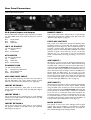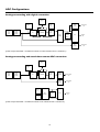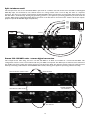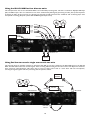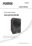
1
Introduction
Important Safety Instructions
Thank you for purchasing the ISA 430 MKII brought to you
by the Focusrite team – Ian, Trevor, Peter, Martin, Tom,
Mick A’C, Phil, Chris G, Micky, Pauline, Melissa, Chris W,
Rob J Snr, Simon J, Vernon, Giles, Rob J Jnr, Mick G, Tim,
Dave, Paul and Simon.
Please read all of these instructions and save them for
future reference. Follow all warnings and instructions
marked on the unit.
The chaps at Focusrite are a jolly hard working bunch and
take a great deal of pride in designing, building and delivering
products which are considered to be the best audio units
around; we hope your new Focusrite unit lives up to that
reputation and that you enjoy many years of productive
recording. If you would like to tell us about your recording
experiences, please email us at: [email protected]
The Focusrite Team
Contents
Introduction....................................................................................... 1
Contents............................................................................................. 1
Important Safety Instructions ........................................................ 1
Power Connections ......................................................................... 1
Rear Panel Connections.................................................................. 2
ISA 430 MKII Front Panel Controls ............................................. 3
Metering.............................................................................................. 3
Input Stage.......................................................................................... 4
EQ Module......................................................................................... 5
Compressor....................................................................................... 6
Gate ..................................................................................................... 8
De-Esser ............................................................................................. 9
Output ................................................................................................ 9
Inserts and Routing Matrix...........................................................10
Soft Limiter ......................................................................................13
Optional Analogue to Digital Converter (ADC) ....................13
Digital Output Front Panel Controls.........................................14
ADC Configurations......................................................................15
Mic Pre-amp Input Impedance.....................................................16
Applications......................................................................................17
FAQs .................................................................................................21
Specifications ...................................................................................24
Accuracy ...........................................................................................26
Copyright..........................................................................................26
Warranty ..........................................................................................26
Reset Sheet ......................................................................................27
Focusrite Distributors...................................................................28
•
Do not obstruct air vents in the rear panel. Do not
insert objects through any apertures.
•
Do not use a damaged or frayed power cord.
•
Unplug the unit before cleaning. Clean with a damp
cloth only. Do not spill liquid on the unit.
•
Unplug the unit and refer servicing to qualified service
personnel under the following conditions: if the power
cord or plug is damaged; if liquid has entered the unit; if
the unit has been dropped or the case damaged; if the
unit does not operate normally or exhibits a distinct
change in performance. Adjust only those controls that
are covered by the operating instructions.
•
Do not defeat the safety purpose of the polarised or
grounding type plug. A polarised plug has two blades
with one wider than the other. A grounding type plug
has two blades and a third grounding prong. The wider
blade or the third prong are provided for your safety.
When the plug provided does not fit into your outlet,
consult an electrician for replacement of the obsolete
outlet.
WARNING: THIS UNIT MUST BE EARTHED
BY THE POWER CORD.
UNDER NO CIRCUMSTANCES SHOULD THE
MAINS EARTH BE DISCONNECTED FROM
THE MAINS LEAD.
This unit is capable of operating over a range of mains
voltages as marked on the rear panel. Ensure correct mains
voltage setting and correct fuse before connecting mains
supply. Do not change mains voltage settings while mains
supply is connected. To avoid the risk of fire, replace the
mains fuse only with the correct value fuse, as marked on
the rear panel. The internal power supply unit contains no
user serviceable parts. Refer all servicing to a qualified
service engineer, through the appropriate Focusrite dealer.
Power Connections
There is an IEC mains lead supplied with the unit which
should have the correct moulded plug for your country.
The wiring colour code used is:
For units shipped to the USA, Canada, Taiwan and Japan:
Live - Black Neutral - White Earth - Green
For units shipped to any other country:
Live - Brown Neutral - Blue Earth - Green and Yellow
1
Rear Panel Connections
(Optional A/D Card shown fitted)
XLR (Audio) Inputs and Outputs
INSERT SEND 2
All 3-pin XLR audio connectors (main and post-mic outputs,
mic, line & ADC inputs, insert sends & returns) are wired as
follows:
Pin 1
Screen/chassis
Pin 2
Audio 0°
Pin 3
Audio 180°
This is used as the insert 2 output point, or as the analogue
output from the dynamics module in ‘Dyn Split mode’ (see
‘Dynamics Split’ diagram on page 10).
POST-MIC OUTPUT
This is used as an output from the point immediately after
the Phase section (i.e. before EQ and dynamics modules)
allowing direct recording of mic, line or instrument inputs. It
provides a direct-to-tape, ultra-short signal path output.
Taking a signal from the POST-MIC OUTPUT does NOT
interrupt a signal routed from the mic-pre to the EQ,
dynamics etc., so a direct feed to tape can be achieved
whilst simultaneously allowing processing of the same
source.
INST. HI Z INPUT
1/4” jack wired as follows:
Tip
Audio 0°
Sleeve Screen/chassis
KEY INPUTS
1/4” jack wired as follows:
Tip
Audio 0°
Ring
Audio 180°
Sleeve Screen/chassis
ADC INPUT 1
ADC Input 1 is used to route an external signal directly to
the optional A/D card via the limiter. When selected using
the ADC Input 1 button on the front panel, ADC Input 1
replaces the internal processed signal being fed to the left
side of the A/D card (i.e. whatever is connected to the mic,
line or instrument input no longer routes to the ADC). For
further detail see ADC Input 1 & 2 on page 13. It also
allows a signal to be summed with the processed signal from
the unit by pressing the Ext Sum switch and using the Ext
Level controls. This signal can be routed to the A/D card
and main output (See ADC Input 1 & 2 on page 13.)
DYNAMIC LINK
1/4” jack wired as follows:
Tip
Compressor sidechain link
Ring
Gate sidechain link
Sleeve Screen/chassis
MIC/LINE/INST INPUT
Any one of these inputs may be used as the main input to
the ISA 430 MKII’s main input. Signals routed to these
inputs are referred to as the ‘Internal’ or ‘Int’ signal path.
ADC INPUT 2
This is used as the insert 1 output point, or as the analogue
output from the EQ module in ‘EQ Split mode’ (see ‘EQ
Split’ diagram on page 10).
ADC Input 2 is also used to route an external signal directly
to the optional A/D card via the limiter. When selected
using the ADC Input 2 button on the front panel, ADC
Input 2 replaces the internal unprocessed signal being fed
to the right side of the A/D card (i.e. whatever is connected
to the mic, line or instrument input). This still allows the
processed signal (i.e. whatever is connected to the mic, line
or instrument input) to route to the left side of the A/D
card. Hence there are four possible setups for the ADC 1 &
2 input switches. (See ADC Input 1 & 2 on page 13.)
INSERT RETURN 2
MAIN OUTPUT
This is used as the insert 2 input point, or as the input to
the dynamics modules in ‘Dyn Split mode’ (see ‘Dynamics
Split’ diagram on page 10).
This output is used as the main analogue internal signal
output, and is fed by whatever is connected to the MIC
INPUT, LINE INPUT or INST INPUT, after this signal has
been routed through the processing modules.
INSERT RETURN 1
This is used as the insert 1 input point, or as the input to
the EQ modules in ‘EQ Split mode’ (see ‘EQ Split’ diagram
on page 10).
INSERT SEND 1
2
gates to maximum (fully clockwise). The second unit will
then act as ‘master’, allowing one set of parameter changes
to affect both compressors or gates identically. NB: The deessers are not linked.
DYNAMIC LINK
You can connect two ISA 430 MKII units (using a standard
TRS 1/4” jack-to-jack lead between the DYNAMIC LINK
sockets) to allow both the compressor and gate sections to
behave as stereo pairs of processors. When connected in
this way, the compressors and gates behave as single stereo
devices. Both units respond to the higher of the two input
signal path levels. (The EQ channels can be matched visually
or aurally to be used as a stereo pair if required.) Hence, to
drive the compressors and gates as stereo pairs, set the
threshold pot of one of the compressors and one of the
Retrofitting the Optional A/D Card
The optional A/D card can be retrofitted to a standard ISA
430 MKII at any time. Full fitting instructions for this option
are included with the Card.
ISA 430 MKII Front Panel Controls
VU meter when the Listen switches are pressed in the
compresser, gate or de-esser sections. The Listen LED will
also light when any of these switches are selected.
Power
Applies power to the unit. Turn on the ISA 430 MKII before
powering up devices to which the outputs are connected.
Meter 0VU Calibration
Inst Input
The metering calibration for the input level and insert
return levels can be shown over two different ranges:
Unbalanced instrument sources may either be connected via
the rear panel INST. HI Z INPUT, or via this duplicated
front panel jack. If both are connected, the front connection
overrides the rear connection. No DI box is required.
•
•
Metering
0VU corresponds to +4dBu.
0VU corresponds to +18dBu.
Either can be selected via the Meter 0VU Calibration
button. For the compressor, the meter indicates the
amount of gain reduction applied, from 0VU (no
compression) to -20VU (corresponding to 20dB of gain
reduction). NB: The effect upon ‘Listen’ of calibration is
similar to that on input and insert returns. However, as the
signal being monitored by the listen circuit is a sidechain
source, the meter acts more as a visual indication of the
attack and decay of a signal, rather than true level.
Listen LED
This illuminates when Listen is selected on the compressor,
expander/gate or de-esser, and indicates that the unit is
monitoring the selected sidechain frequencies. N.B. When
attempting to listen to the dynamics in ‘Split Dynamics’
mode, pressing the Listen switch will only result in visual
monitoring; as the dynamics are split from the monitoring
path, they can be viewed in the meter but not heard.
Meter Source
The VU meter can display input level, Insert 1 return level,
Insert 2 return level, compressor gain reduction or
sidechain Listen level. Press the Meter Source button to
step through Input, Insert Rtn 1, Insert Rtn 2 and Comp
sources as indicated by the corresponding LEDs. The
sidechain Listen level will automatically be displayed on the
Audio O/L LED
This LED illuminates when the peak signal level reaches or
exceeds +20dBu, or when the peak signal level reaches 6dB
below the clip point. The signal is monitored at five points:
post-the input gain Trim, post-Insert 1, post-the EQ
3
3
legend). The gain range is split between two gain modes
depending upon the status of the 30-60 switch:
module, post-Insert 2, and post-the Dynamics module (since
each module could cause clipping if incorrectly set up).
Occasional short-duration peaks which may cause the LED
to blink will not normally cause audible distortion, but if the
LED is lit constantly, the level in the appropriate module
should be reduced to prevent overloading.
Mode 1: Mic Gain Range 0-30
With the 30-60 switch off, the rotary gain knob operates
over a gain range of 0dB to +30dB, the level of gain chosen
being indicated on the front panel by the outer arc of yellow
numbers around the gain knob.
Digital Output Meters
Mode 2: Mic Gain Range 30-60
With the 30-60 switch on (illuminated), the rotary gain
knob operates over a gain range of 30dB to 60dB, the level
of gain chosen being indicated on the front panel by the
outer arc of yellow numbers around the gain knob.
Two LED bargraph meters
monitor the level being fed
to the output (left meter)
and input (right meter) of
the unit.
An additional 20dB of gain can be applied to the signal after
the Mic/Line gain knob using the Trim knob. See Trim
control text below for full explanation.
They also display the
channels of the optional
ADC card when the ADC
Input 1 and ADC Input 2
switches are selected. The
meters provide a wide
range from –42dBFS (20dBu) to 0dBFS (+22dBu).
Line Input Gain
With the line input selected, the user has access to gain
settings ranging from –20dB to +10dB, indicated on the
front panel by the arc of white numbers around the gain
knob. The 30-60 switch is inactive when the line input is
selected, as the gain range for Line level inputs is restricted
to –20dB to +10dB in 10dB steps.
The output meter monitoring point is just before the ADC
input; this means that if the limiter is switched in the action
of the limiter can be seen on the meter. This monitor point
is also post-the output level control. When ADC Input 1 is
selected the meter is fed from ADC Input 1. The input
meter monitoring point is post-the phase switch. When
ADC Input 2 is selected the meter is fed from the ADC
Input 2.
An additional 20dB of gain can be applied to the signal after
the Mic/line gain knob using the Trim knob. See Trim
control text below for full explanation.
Instrument Input Gain
With the instrument input selected, gain is applied to the
input signal by using the Trim control only, which allows
+10dB to +40dB of gain range. The level of gain chosen is
indicated on the front panel by the outer arc of yellow
numbers around the gain knob. This input is suitable for
high impedance sources such as guitar or bass pickups
(which may be connected directly without the need for an
external DI box), or vintage synthesizers with high
impedance outputs.
Input Stage
Three input options are
provided
to
give
compatibility with mic,
line or instrument
sources. An immediatelypost-input-stage, balanced
output
(POST-MIC
OUTPUT) is provided on
the rear panel giving an ultra-short signal path to allow for
the cleanest possible recordings. N.B. The POST-MIC
OUTPUT can be used in conjunction with the main output,
allowing the user to record a dry signal for archive/safety
purposes, at the same time as recording the processed
output.
Trim
The Trim control provides additional variable gain of 0dB to
+20dB when mic or line inputs are selected. The level of
gain chosen is indicated on the front panel by the inner arc
of white numbers around the gain knob. The additional
20dB of gain that can be applied to the Mic or Line signal is
very useful for two reasons:
When high gain is required
The trim used in conjunction with the Mic gain of 60dB will
give a total of up to 80dB of pre-amp gain, making it very
useful for getting good digital recording levels from very low
output devices, such as dynamic and ribbon microphones.
Select
Pressing Select steps through each of the three inputs as
indicated by the corresponding LEDs. When the Mic LED is
lit, the mic input is active etc. Only one of the Mic, Line or
Instrument inputs can be used.
Gain adjustment during recording
When small amounts of gain adjustment are needed to
correct for performance level variations during recording,
use the trim knob rather than the stepped Mic/Line gain
knob, as switching the 10dB gain steps will be much too
Mic Input Gain
With the mic input selected, the user has access to the full
gain range in 10dB steps from 0dB to +60dB (yellow
4
intrusive. It is therefore good practice to apply some Trim
gain before using the 10dB stepped gain knob to find the
optimum recording level so that the Trim control can be
used to gently add or take away gain later, if so required.
Impedance
Pressing Impedance steps through each of the four
transformer pre-amp input impedance values, as indicated
by their corresponding LEDs. By selecting different values
for the impedance of the ISA 430 MKII transformer input,
the performance of both the ISA 430 MKII pre-amp and the
microphone connected can be tailored to set the desired
level and frequency response.
+48V
Pressing the +48V switch provides +48V phantom power,
suitable for condenser microphones, to the rear panel XLR
microphone connector. This switch does not affect the
other inputs. If you are unsure whether your microphone
requires phantom power, refer to its handbook, as it is
possible to damage some microphones (most notably
ribbon microphones) by providing phantom power.
Mic Air
Pressing Mic Air increases the impedance effect of the
transformer on high frequencies. Transformers impart an
effect which is often referred to as ‘air’, adding a
spaciousness to the sound of the mic pre-amp. Mic Air
further emphasises this effect. For further deails see FAQ
number 18 on page 22.
Phase
Pressing Phase inverts the phase of the selected input. This
is primarily used to correct phase problems when using
multiple microphones on a single source.
EQ Module
All EQ
Low Pass Filter
Pressing All EQ activates all sections of the EQ module
(including the Hi and Lo Pass Filters), placing the whole
module in the audio path. Toggling All EQ allows an A/B
comparison of EQ’d/flat settings, without having to switch
each section of the EQ individually, and without using
Bypass which switches both EQ and dynamics modules in or
out of the audio path. The Comp and Gate switches on
individual EQ sections (see below) operate independently
from the All EQ switch.
Sets a roll-off frequency from 400Hz to 22kHz.
High Pass Filter
Sets a roll-off frequency from 20Hz to 1k6Hz.
Comp
When the Comp switch is pressed, both Hi and Lo pass
filters are inserted in the compressor sidechain to enable
frequency-selective (aka frequency-conscious) compression.
This selection is cancelled if Filter In or Gate is pressed.
Filter In
Press Filter In to make the Hi and Lo Pass Filters active in
the audio path. This selection is cancelled if Comp or Gate
is pressed. Both filters provide 18dB/octave roll-off, and
since the filter frequencies overlap they may be configured
as a very tight bandpass filter for creative compression and
gating; use when you wish to select a specific instrument or
narrow frequency band from a complex signal, then feed to
the sidechain of the compressor or gate.
Gate
When the Gate switch is pressed both filters are inserted in
the gate sidechain to enable accurate drum gating. This
selection is cancelled if Filter In or Comp is pressed.
Parametric EQ
Two separate bands of parametric EQ, hi-mid and low-mid,
are provided, each with continuously variable boost/cut
with centre detent, sweep control with two ranges, and
fully variable Q. The first band covers the range 40Hz to
400Hz (120Hz to 1k2Hz when x3 is pressed) and the
second band covers 600Hz to 6kHz (1k8Hz to 18kHz when
x3 is pressed).
5
Shelving EQ In
Press in to switch the shelving EQ into the signal path. This
selection is cancelled if Gate or Comp is pressed.
Hi Range
The frequency controls have two ranges, the higher being
selected when the Hi Range switch is pressed (frequencies
shown in yellow on the panel).
HIGH SHELF
LOW SHELF
33
Param EQ In
20
HI RANGE
460
655
2k2
1k5
HI RANGE
18k
15k
0Hz
Press in to switch the parametric EQ into the signal path.
This selection is cancelled if Gate or Comp is pressed.
Low frequency shelving
x3
The frequency range steps are 20Hz, 56Hz, 160Hz and
460Hz (33Hz, 95Hz, 270Hz and 655Hz when Hi Range
switch is engaged).
The Sweep controls have two ranges, the higher being
selected when the x3 switch is pressed ( x3 frequencies are
shown in yellow on the panel).
High frequency shelving
Comp
The frequency range steps are 1.5kHz, 3.3kHz, 6.8kHz and
15kHz (2.2kHz, 4.7kHz, 10kHz and 18khz when Hi Range is
engaged).
When the Comp switch is pressed, the parametric EQ is
inserted into the compressor sidechain, allowing frequencyselective (frequency-conscious) compression. This selection
is cancelled if Param EQ In or Gate is pressed.
Comp
When the Comp switch is pressed, the shelving EQ is
inserted into the compressor sidechain, allowing frequencyselective (frequency-conscious) compression. This selection
is cancelled if Shelving EQ In or Gate is pressed.
Gate
When the Gate switch is pressed, the parametric EQ is
inserted into the gate sidechain for e.g. accurate drum
gating. This selection is cancelled if Param EQ In or Comp is
pressed.
Gate
When the Gate switch is pressed, the shelving EQ is
inserted into the gate sidechain for e.g. accurate drum
gating. This selection is cancelled if Shelving EQ In or Comp
is pressed.
Shelving EQ
High and low frequency-shelving sections are available, each
with continuously variable boost/cut with center detent, and
a four position rotary switch for selection of roll-off
frequency. In addition, the Hi Range switch allows for two
ranges of roll-off frequency per band – resulting in eight
frequency selections in total.
Compressor
Comp In
Press Comp In to switch the compressor into the signal
path. Note that the VU meter can be selected to display the
compressor gain reduction (see Metering section, page 3).
6
Listen
Press to allow audio monitoring of the compressor
sidechain to assist accurate frequency adjustment when
setting up frequency-conscious compression. The Listen
LED below the main VU meter illuminates to show that
Listen mode is active. Note that the VU meter automatically
displays the compressor sidechain listen level when a Listen
switch is pressed in (see Metering section, page 3).
Vintage
Attack
The Vintage switch activates the vintage compressor. This
has two modes, Comp and Lim, as indicated by the LEDs to
the right of the Vintage switch. The Vintage switch steps
through the different modes of compressor operation.
Attack determines how quickly compression is applied once
the level of the source signal has risen above the threshold.
When turned anticlockwise the response is very fast, which
tends to make the compressor react to the peak levels of
the signal. This is sometimes desirable, but can cause
unwanted “pumping” of steadier low level components of
the signal by short transients. A slower attack will cause the
compressor to ignore short transients and respond more to
the average loudness of the signal; however this may seem
to increase relative volume of the transients.
In Comp mode the compressor is a vintage opto
compressor. In Lim mode the compressor acts more like a
vintage opto limiter with a harder ratio and knee. When
neither the Comp or Lim LEDs are illuminated the
compressor is in the classic Focusrite discrete Class A VCA
mode.
N.B. When in Vintage Comp or Lim mode the Attack,
Release, Auto Release and Ext Key controls are inactive.
Makeup
Compression results in an overall reduction in level. The
Makeup control allows you to restore the compressor’s
output level back to the original level.
Ratio
The Ratio control determines the rate at which
compression is applied to the signal with increasing input,
and is the ratio of change in input level compared to change
in output level. The control gives a range of 1.5 to 10.
Higher ratio settings will produce more noticeable
compression, so for the least obtrusive result, the ratio
should be set at the minimum necessary for the application.
For example, using low threshold and low ratio will produce
a less noticeable effect than a high threshold and high ratio,
even though the total amount of compression may be the
same.
Release
Release determines how quickly compression is removed
once the level of the source signal has fallen below the
threshold. When in the anticlockwise position, the
compression releases very quickly, which may be
appropriate on rapidly varying signals to avoid compressing
the beats that follow, but can result in excessive distortion
on more sustained material. Clockwise rotation increases
the release time, giving a smoother effect, but which at the
same time may result in transients causing audible
“pumping”.
Theshold
Threshold determines the level at which compression
begins, with a range of -28dB to +12dB. The lower the
threshold, the more the signal is compressed. Setting a
higher threshold allows quieter passages in music or speech
to remain unaffected; only passages that exceed the
threshold will be compressed.
7
in the key input signal by adding gain to the sibilant
frequencies. This will cause those frequencies to be heavily
compressed in the original signal. The ISA 430 MKII’s
dedicated de-esser can take care of primary de-essing
duties, whilst key input compression deals with a secondary
problem occurring at a separate frequency.
Blend and Mix
Press the Blend switch to activate the blend circuit and
make the Mix control active. The Mix control allows the
user to mix a blend of uncompressed signal and compressed
signal (from totally uncompressed to fully compressed).
Equal amounts of compressed and uncompressed signal are
present when the mix control is set to its mid point.
N.B. When attempting to use the compressor blend and the
gate simultaneously, the gate will be less effective. This is
because the original input signal and the processed (gated)
signal are being blended, so the more input signal there is,
the less audible the effect of the gate will be.
Auto Release
Press the Auto Release switch to set the release rate to
auto, substituting an adaptive attack/release circuit which
varies the release rate to suit the dynamics of the signal.
This enables the use of fast attack times without any
“pumping” type artefacts, especially effective on complex
programme material. The release rate is probably the most
important variable when recording rock/pop music, since it
directly affects loudness. Loudness is increased by the
maintenance of high mean levels: compression increases the
proportion of high level signal content, and as the diagram
shows, the faster the unit releases, the more low-level signal
is brought to a higher level. Therefore, the faster the
release rate, the higher the perceived loudness of the
recording.
Gate
Ext Key
Gate In
Pressing Ext Key switches control of the compressor to an
external signal fed into the rear panel COMP KEY INPUT
jack socket. Note that the key input is not output from the
unit (it is the original input that is compressed and output)
but the compression is applied as if the key input signal were
being compressed. N.B. Ext Key is not available in Vintage
mode.
Press Gate In to switch the gate into the signal path.
Expand
Pressing Expand causes the gate to function as an expander,
which has a similar effect to gating, but instead of cutting off
any signal below the threshold, it proportionately decreases
it (see diagram below). This may give a more natural sound
when recording non-percussive sources. Pressing Expand a
second time causes the switch to revert to being unlit, and
causes the section to act as a gate once more. The adjacent
LED meter indicates in dB the amount of gain reduction
applied by the expander/gate, and provides additional visual
indication of the effect of the Range control (see below).
Example: one of the problems in compressing a mixed
programme is that gain reduction tends to be controlled by
one dominant instrument or sound. For more natural
compression, you need to attenuate the sound of the
dominant instrument, but this is probably not acceptable
since it would affect the mix.
Using the key input allows a second feed of the input signal
to be routed through an equaliser to attenuate the
dominant instrument. That signal is then fed into the key
input. Now you can use the attenuated key input to control
the compression of the original signal. The original signal is
compressed as if the dominant instrument had been
attenuated. This technique can be very useful when
compressing bass-heavy dance music. By attenuating the
bass in the key input signal, the bass in the original retains
more of its dynamics.
Listen
Press to allow audio monitoring of the gate sidechain to
enable accurate frequency adjustment during setup. The
Listen LED below the main VU meter illuminates to show
that Listen mode is active. Note that the VU meter
Another application of this technique is to create a second
de-esser. When de-essing, sibilant frequencies need to be
heavily compressed. To achieve this, accentuate the sibilants
8
automatically displays the gate sidechain listen level when a
Listen switch is pressed in (see Metering section, page 3).
De-Esser
Range
Range determines how much the signal is attenuated when
the gate is closed. The gate can be set up to cut (80dB
attenuation, control clockwise) or to more gently lessen
attenuation (min 0dB). Maximum attenuation may give an
unnatural sound, so keep Range at a low value unless it is
essential to reduce high levels of background noise, or
unless an obviously gated effect is desired.
The de-esser uses an optical design, allowing the user to
remove excessive sibilance from a vocal performance
(where “ess” sounds are over-emphasised).
Threshold
Threshold determines the level at which the gate opens (or
at which gain reduction finishes when in Expander mode).
The higher the threshold, the more low-level noise is
reduced, and the more extreme the effect.
De-Ess In
Press in to activate the De-Esser.
Threshold
Hold
Threshold determines how much de-essing is being applied
to the selected frequency. The lower the threshold (control
anticlockwise) the more de-essing is applied.
Hold controls the variable delay before the gate release
starts. This allows the gate to be held open until the signal
has decayed sufficiently, so that the rapid onset of gain
reduction isn’t noticeable. Alternatively the signal can be
deliberately truncated before its natural end to create a
special effect.
Freq
This control selects the frequency to be removed; between
2k2Hz and 9k2Hz.
Release
De-Ess Listen
This control sets the Release time, the rate at which the
gate attenuation increases, fading out the signal. This release
period begins as soon as the signal drops below the
threshold. On transient signals, a fast release will be
appropriate (control anticlockwise), but with other material,
a slower release (control clockwise) may give a more
natural sound. Ideally the release needs to be slightly slower
than the natural decay rate of the signal to avoid audibly
cutting it short.
Press to allow monitoring of only those signals which will
trigger activation of the de-esser, rather than hearing the
overall effect in a complex full bandwidth signal. The Listen
LED below the main VU meter illuminates to show that
‘Listen’ mode is active. Note that the VU meter
automatically displays the de-ess listen level when the Listen
switch is pressed in (see Metering section, page 3).
Active LED
Fast Attack
The Active LED illuminates when the de-esser is active at
the chosen frequency, and shines more brightly with
increasing level reduction.
Fast Attack determines how quickly the gate opens once
the level of the source signal has risen above the threshold.
When the switch is pressed, the response is fast, which may
be necessary on some signals to avoid “missing” an initial
transient, but which could also introduce an undesirable
click on smooth, sustained sounds when using a high
threshold setting. On such signals a slower attack (switch
released) may give a more natural sound.
Setting up the De-Esser
Press De-Ess Listen with Threshold at maximum and slowly
reduce until the selected frequency begins to trigger the deesser. Vary the frequency control to find the exact area of
the signal which you wish to remove. Once located, switch
off De-Ess Listen and adjust Threshold for the amount of
reduction required. No further adjustment of Freq should
be required, as the hot spot will have been precisely found
using De-Ess Listen.
Hyst
Press to introduce wider hysteresis. This increases the level
difference between the gate switching on and off, which
prevents the gate from oscillating (‘chattering’) with
particular combinations of input signal and threshold setting.
This function is particularly useful when gating a signal with
a very long decay time and large amounts of level
modulation (e.g. a grand piano).
Output
Ext Sum
Ext Key
Press to route a sum of both the
internal signal and external line input
signal (from the EXT SUM INPUT) to
the Main Output. External signals could
Pressing Ext Key switches control of the gate to an external
signal on the rear panel GATE KEY INPUT jack.
9
be a double track, an extra mic from a second ISA 430
MKII, or live reverb.
Mute
Ext Level
Press to mute the output of both the Main Output and
Post-Mic Output. N.B. Analogue sends and digital outputs
are not muted.
This control adjusts the gain of the external line input which
may be summed into the Main Output (see above).
Bypass
All EQ and dynamics processing modules can be globally
switched out using the Bypass switch, for quick A/B
comparison of processed/unprocessed signals.
Output
Adjusts the Main Output level between -60dB and +6dB.
Inserts and Routing Matrix
The ISA 430 MKII has two insert points and a very comprehensive set of routing options.
Insert 1
EQ Split
Activated by the Insert 1 In switch. The insert 1
send and return are both balanced XLRs and are
situated post- the Phase switch. Insert 1 Send and
Return always remain pre- any of the processing
sections (EQ, dynamics etc).
Activated by the EQ Split switch. This allows the INSERT
SEND 1 and INSERT RETURN 1 connections to act as
inputs and outputs to the EQ section only, thus giving a
separate line level EQ unit, which acts independently from
the dynamics processing. When EQ Split is selected, the
Insert 1 switch, if lit, wll go out. This is because Insert 1 is
now being used as the input and output to the EQ section,
and so is no longer available for use as a ‘traditional’ insert.
Using Insert 1 as ‘traditional’ insert:
Using Insert 1 to split EQ:
MIC
LINE
INST
INSERT
1
SEND
INSERT
1
RETURN
LEVEL
TRIM &
PHASE
MIC
LINE
INST
EQ
INSERT
1
RETURN
INSERT
1
SEND
DYNAMICS
EQ
LEVEL
TRIM &
PHASE
DYNAMICS
Dynamics Split
Activated by the Dyn Split switch. This allows the INSERT SEND 2 and INSERT RETURN 2 connections to act as independent
inputs and outputs to the dynamics section only, thus giving a separate line level dynamics unit. When Dyn Split is selected, the
Insert 2 and Post-Dyn switches, if lit, will go out. This is because Insert 2 is now being used as the input and output to the
dynamics section, and so is no longer available for use as a ‘traditional’ insert.
Using Insert 2 to split dynamics:
MIC
LINE
INST
INSERT
1
SEND
INSERT
2
RETURN
INSERT
1
RETURN
INSERT
2
SEND
EXT
SUM
DYNAMICS
LEVEL
TRIM &
PHASE
O/P
LEVEL
EQ
10
LIMITER
ANALOGUE
OUTPUT
ADC
METERS
Dynamics position switch
Allows the dynamics section to be placed in three different positions in the processing chain. (Normally the dynamics
section is the second processing section in the signal path, after the EQ section.) When activated, the new position of the
dynamics section is indicated by the LEDs below the Dynamics switch.
a) Dynamics Post-EQ (Default)
MIC
LINE
INST
INSERT
1
SEND
INSERT
1
RETURN
LEVEL
TRIM &
PHASE
INSERT
2
SEND
INSERT
2
RETURN
EQ
EXT
SUM
O/P
LEVEL
DYNAMICS
LIMITER
ANALOGUE
OUTPUT
ADC
METERS
b) Dynamics Pre-EQ
Pressing Dynamics once reverses the position of the EQ and dynamics sections, placing dynamics first and EQ afterwards. The
Pre-EQ LED illuminates to provide visual confirmation of the dynamics’ pre-EQ position.
MIC
LINE
INST
INSERT
1
SEND
INSERT
1
RETURN
LEVEL
TRIM &
PHASE
INSERT
2
SEND
DYNAMICS
INSERT
2
RETURN
EXT
SUM
O/P
LEVEL
EQ
LIMITER
ANALOGUE
OUTPUT
ADC
METERS
c) Dynamics Post-Sum
Pressing Dynamics a second time places the dynamics section after the Ext Sum, Ext Level and Output faders but before the
limiter. The Post-Sum LED illuminates to provide visual confirmation of the dynamics’ POST-SUM position. This allows the
external signal, which has been summed to the main input signal, to be processed through the dynamics section of the ISA 430
MKII. Pressing Dynamics a third time returns the dynamics section to its default position (post-EQ, pre-Sum) where both the
Pre-EQ and Post-Sum LEDs are unlit.
MIC
LINE
INST
LEVEL
TRIM &
PHASE
INSERT
1
SEND
INSERT
1
RETURN
INSERT
2
SEND
INSERT
2
RETURN
EXT
SUM
O/P
LEVEL
EQ
11
DYNAMICS
LIMITER
ANALOGUE
OUTPUT
ADC
METERS
Insert 2
Activated by the Insert 2 In switch. The insert 2 send and return are both balanced XLRs and can be placed in four
different positions in the signal path dependant upon the relative positions of the Post-Dyn and Dyn Split switches. (N.B.
It is not possible to have the following combination of switches for Insert 2: Insert 2 In + Post-Dyn + Dynamics PostSum.)
a) Insert 2 In
Insert 2 placed post-EQ and pre-dynamics.
MIC
LINE
INST
INSERT
1
SEND
INSERT
1
RETURN
LEVEL
TRIM &
PHASE
INSERT
2
SEND
INSERT
2
RETURN
EXT
SUM
EQ
DYNAMICS
O/P
LEVEL
INSERT
2
RETURN
EXT
SUM
LIMITER
ANALOGUE
OUTPUT
ADC
METERS
LIMITER
ANALOGUE
OUTPUT
ADC
METERS
LIMITER
ANALOGUE
OUTPUT
ADC
METERS
LIMITER
ANALOGUE
OUTPUT
ADC
METERS
b) Insert 2 In + Post-Dyn
Insert 2 placed post-dynamics and post-EQ
MIC
LINE
INST
INSERT
1
SEND
INSERT
1
RETURN
LEVEL
TRIM &
PHASE
INSERT
2
SEND
EQ
O/P
LEVEL
DYNAMICS
c) Insert 2 In + Dynamics Post-Sum
Insert 2 placed post-EQ and pre-sum/pre-dynamics (dynamics have moved post-sum).
MIC
LINE
INST
INSERT
1
SEND
INSERT
1
RETURN
LEVEL
TRIM &
PHASE
INSERT
2
SEND
INSERT
2
RETURN
EXT
SUM
O/P
LEVEL
EQ
DYNAMICS
d) Insert 2 In, Post-Dyn + Dynamics Pre-EQ
Insert 2 placed post-dynamics and pre-EQ.
MIC
LINE
INST
LEVEL
TRIM &
PHASE
INSERT
1
SEND
INSERT
1
RETURN
INSERT
2
SEND
INSERT
2
RETURN
EXT
SUM
DYNAMICS
EQ
(Examples a-d show Insert 2 being used as a ‘traditional’ insert.)
12
O/P
LEVEL
whatever is connected to the mic, line or instrument input,
and feeds the left side of the A/D converter in its place. The
pre-processed signal is still fed to the post-mic output, and
this is still also fed to the right side of the A/D converter.
Soft Limiter
Press to activate the soft limiter.
The soft limiter circuit acts by
gradually increasing the ratio of
the limiter as the signal exceeds
the threshold. The threshold is
set at –6dBFS (+16dBu). Signal
levels between –6dBFS and
–4dBFS have a ratio of 1.5:1
applied to them, signal levels between –4dBFS and 0dBFS
have a ratio of 2:1 applied to them, and signal levels
between 0dBFS and +6dBFS have a ratio of infinite:1 applied
to them.
With the ADC Input 1 switch unlit and ADC Input
2 switch lit, whatever is connected to the mic, line or
instrument input feeds the main analogue output, and feeds
the left side of the A/D converter. Both signals are postprocessing. Whatever is connected to ADC input 2 cuts the
unprocessed signal fed from the mic, line or instrument
input, and feeds the right side of the A/D converter in its
place.
With ADC Input 1 and 2 switches both lit,
whatever is connected to ADC input 1 cuts whatever is
connected to the mic, line or instrument input, and feeds
the left side of the A/D converter in its place. Whatever is
connected to ADC input 2 cuts the unprocessed signal fed
from the mic, line or instrument input, and feeds the right
side of the A/D converter in its place. See ADC
Configurations diagrams on page 15.
The attack and release times for the limiter are
instantaneous. This means that the audio is “clamped down”
so that the signal can never go above the maximum level
that the ADC can accurately convert (0dBFS).
Consequently, it is impossible to overload the connected
optional ADC card when the soft limiter is active.
24-bit/96kHz ADAT™ (optical/
lightpipe) interface operation
Optional Analogue to Digital
Converter (ADC)
The card provides digital outputs for both ISA 430 MKII
ADC input channels, which operate over the sample
frequency ranges 44.1, 48, 88.2 and 96kHz, and can be
dithered to 16-, 20-, or 24-bit depths depending upon the
destination. The card features an ADAT™-type ‘lightpipe’
output and SPDIF Toslink output connectors. ADAT™
lightpipe cables are available from your local dealer, or in
the UK from Studiospares (tel +44 (0)20 7482 1692): stock
number 585-510.
The ISA 430 MKII can be used as a high quality two-channel
ADC to convert analogue signals to the digital domain, by
adding the optional ISA 430 MKII digital output board. The
two external ADC inputs and the main channel inputs can
all be fed to the ADC, via the soft limiter, ensuring superclean, protected, high-quality digital conversion.
Alternatively, two ISA 430 MKII units with a single A/D
option can be used to create a stereo tracking/mixdown to
digital system (see ‘Stereo ISA 430 MKII Units’ on page 20).
24-bit/192kHz AES/SPDIF operation
The card also provides AES and SPDIF format outputs via a
9-pin D-type connector on the rear panel. The full range of
sample rates (up to 192kHz) and bit depths are available. To
access the digital signals from the 9-pin D-type output
connector, the A/D card must be purchased with either an
AES or SPDIF D-type conversion cable as follows:
Digital formats available on the ADC are AES, SPDIF
(optical and coaxial RCA phono) and ADAT™ optical
format. (The ADAT™ outputs can also operate in high
speed SMUX mode for 96kHz transfer speeds, but are
muted during 192kHz operation.) N.B. If RCA phono
(SPDIF) or XLR (AES) connections are required, the
relevant 9-pin D-type to RCA phono or XLR breakout
cable is required. For installation details, see separate A/D
option user guide.
AES cable: 9-pin D-type to 4 male XLR
SPDIF cable: 9-pin D-type to 4 male RCA phono
ADC Input 1 and 2
With the ADC Input 1 and 2 switches both unlit,
whatever is connected to the mic, line or instrument input
feeds the main analogue output, and also feeds the left side
of the A/D converter. Both signals are post-processing. A
pre-processed signal is fed to the post-mic output, and this
pre-processed signal is also fed to the right side of the A/D
converter.
With the ADC Input 1 switch lit and ADC Input 2
switch unlit, whatever is connected to ADC input 1 cuts
13
Note: cables need to be purchased separately. Since there
are two different cable options – XLR for AES and RCA
phono for SPDIF – these are not included with the A/D
converter options. Focusrite cables may be purchased from
your local dealer. If you experience difficulty in obtaining
these cables, contact your local distributor as listed in the
back of this manual.
makes the ISA 430 MKII useable with both old and new
equipment.
Word Clock In and Out
The internal ADC can be synchronised to an external word
clock. By pressing the front panel Ext Sync switch, the ISA
430 MKII can be switched to lock to either standard
external word clock or 256X external word clock.
AES/SPDIF Connector Configuration
The 9-pin D-type connector labeled AES/SPDIF can be
configured either as an AES or SPDIF dedicated output
using the AES/SPDIF switch next to it. When operating the
connector in AES mode an AES cable is required. When
operating in SPDIF mode the SPDIF RCA cable should be
used, which automatically sets the output stream to
consumer mode.
Either type of external word clock should be connected to
the ISA 430 MKII ADC card at the WORD CLOCK IN
BNC connector. The WORD CLOCK OUT BNC
connector either regenerates the external word clock
connected at the word clock input connector (if locked to
an external clock source) or transmits the internal sample
frequency of the ADC card (if the ISA 430 MKII is acting as
word clock master).
The 1 Wire/2 Wire switch selects 1 wire or 2 wire mode
for the AES output as follows:
1 WIRE MODE
Where the ISA 430 MKII is being used as a slave device
within a larger digital system, the WORD CLOCK OUT
BNC connector can be used to pass on the external word
clock signal to the next device. When the unit is not slaved
to another device and is in internal clock mode, the word
clock output connector outputs the sample frequency
selected on the ISA 430 MKII front panel.
AES XLR
BREAKOUT CABLE
BLACK
CH 1+2
RED
CH 1+2
YELLOW
CH 1+2
BLUE
CH 1+2
9 WAY
D-TYPE
Digital Output Front Panel
Controls
Clock Select
2 WIRE MODE
AES XLR
BREAKOUT CABLE
BLACK
CH 1
RED
CH 2
YELLOW
CH 1
BLUE
CH 2
Pressing this switch allows the
user to select between sample
frequencies of 44.1kHz, 48kHz,
88.2kHz, 96kHz, 176.4kHz, and
192kHz.
9 WAY
D-TYPE
Bit Depth Select
Pressing this switch allows the user to select between 24-,
20- and 16-bit depths.
1 Wire mode
Selected with the switch in the ‘out’ position. The AES
connector transmits two channels of AES data
simultaneously for all sample frequencies from 44.1 to
192kHz, over a single wire.
Ext Sync
Pressing Ext Sync allows the ISA 430 MKII to be slaved to
an external word clock source. Selecting 256X allows the
ISA 430 MKII to be slaved to an external clock running at
256 times faster than the sample frequency and enables
connection to systems such as the Digidesign 'Superclock'
or other 256 slave clock devices.
2 Wire mode
Selected with the switch in the ‘in’ position. The AES
connector transmits one channel of AES data only per cable,
for all sample frequencies from 96kHz to 192kHz. The
reason for the two modes is that older equipment with
96kHz and 192kHz AES inputs can only receive speeds up
to 192kHz by using both digital channels of a single AES
connection (known as ‘2 wire’). Therefore one AES channel
can send only a single channel of digital data. This switch
Lock LED
When lit, LOCK indicates that the unit is synchronised to
an external clock source.
14
ADC Configurations
Analogue recording with digital conversion
INSERT
2
INSERT
1
MIC
LINE
INST
EXT
SUM
MAIN
OUTPUT
ANALOGUE
O/P
1
LEVEL
TRIM &
PHASE
EQ
DYNAMICS
O/P
LEVEL
OUTPUT
SOFT
LIMITER
DYN PRE EQ SWAP
DYN POST SUM SWAP
ADC
METERS
DIGITAL
O/P
INPUT
2
POST
MIC
OUTPUT
(In this example both ADC 1 and ADC 2 switches are unlit and Soft Limiter is switched in.)
Analogue recording and stand-alone stereo ADC conversion
INSERT
2
INSERT
1
MIC
LINE
INST
LEVEL
TRIM &
PHASE
EQ
DYNAMICS
DYN PRE EQ SWAP
O/P
LEVEL
MAIN
OUTPUT
ANALOGUE
O/P
POST
MIC
OUTPUT
ANALOGUE
O/P
DYN POST SUM SWAP
1
ADC 1
I/P
SOFT
LIMITER
METERS
ADC 2
I/P
ADC
2
(In this example both ADC 1 and ADC 2 switches are lit and Soft Limiter is switched in.)
15
DIGITAL
O/P
ANALOGUE
O/P
Mic Pre-amp Input Impedance
average microphone, around 1.2kΩ to 2kΩ. (The original
ISA 110 pre-amp design followed this convention and has an
input impedance of 1.4kΩ at 1kHz.)
A major element of the sound of a mic pre-amp is related
to the interaction between the specific microphone being
used, and the type of mic pre-amp interface technology to
which it is connected. The main area in which this
interaction has an effect is the level and frequency response
of the microphone, as follows:
•
Level: Professional microphones tend to have low
output impedances, so more level can be achieved by
selecting the higher impedance positions of the ISA 430
MKII mic pre-amp.
•
Frequency response: Microphones with defined
presence peaks and tailored frequency responses can
be further enhanced by choosing lower impedance
settings. Choosing higher input impedance values will
tend to emphasise the high frequency response of the
microphone connected, allowing improved ambient
information and high end clarity, even from averageperformance microphones.
Input impedance settings greater than 2kΩ tend to make
the frequency-related variations of microphone output less
significant than at low impedance settings. Therefore high
input impedance settings yield a microphone performance
that is more flat in the low and mid frequency areas and
boosted in the high frequency area when compared to low
impedance settings.
Ribbon microphones
The impedance of a ribbon microphone is worthy of special
mention, as this type of microphone is affected enormously
by pre-amp impedance. The ribbon impedance within this
type of microphone is incredibly low, around 0.2Ω, and
requires an output transformer to convert the extremely
low voltage it can generate into a signal capable of being
amplified by a pre-amp. The ribbon microphone output
transformer requires a ratio of around 1:30 (primary:
secondary) to increase the ribbon voltage to a useful level,
and this transformer ratio also has the effect of increasing
the output impedance of the mic to around 200Ω at 1kHz.
Various microphone/ISA 430 MKII pre-amp impedance
combinations can be tried to achieve the desired amount of
colouration for the instrument or voice being recorded.
This transformer impedance, however, is very dependent
upon frequency - it can almost double at some frequencies
(known as the resonance point) and tends to roll off to very
small values at low and high frequencies. Therefore, as with
the dynamic and condenser microphones, the mic pre-amp
input impedance has a massive effect on the signal levels and
frequency response of the ribbon microphone output
transformer, and thus the ‘sound quality’ of the
microphone. It is recommended that a mic pre-amp
connected to ribbon microphone should have an input
impedance of at least 5 times the nominal microphone
impedance.
To understand how to use the impedance selection
creatively it may be useful to read the following section on
how the microphone output impedance and the mic preamp input impedance interact.
Switchable Impedance: In Depth
Explanation
Dynamic moving coil and condenser mics
Almost all professional dynamic and condenser
microphones are designed to have a relatively low nominal
output impedance of between 150Ω and 300Ω when
measured at 1kHz. Microphones are designed to have such
low output impedances because the following advantages
apply:
•
•
For a ribbon microphone impedance of 30Ω to 120Ω the
ISA 430 MKII’s input impedance of 600Ω (Low) will work
well, and for 120Ω to 200Ω ribbon microphones the input
impedance setting of 1.4kΩ (ISA 110) is recommended.
They are less susceptible to noise pickup.
They can drive long cables without high frequency rolloff due to cable capacitance.
Impedance Setting Quick Guide
High mic pre-amp impedance settings
• Will generate more overall level
• Will tend to make low- and mid-frequency response of
the microphone flatter
• Will improve high-frequency response of the
microphone.
The side-effect of having such low output impedance is that
the mic pre-amp input impedance has a major effect on the
output level of the microphone. Low pre-amp impedance
loads down the microphone output voltage, and emphasises
any frequency-related variation in microphone output
impedance. Matching the mic pre-amp resistance to the
microphone output impedance, (e.g. making a pre-amp input
impedance 200Ω to match a 200Ω microphone) still
reduces the microphone output and signal to noise ratio by
6dB, which is undesirable.
Low pre-amp impedance settings
• Will reduce the microphone output level
• Will tend to emphasise the low- and mid-frequency
presence peaks and resonant points of the microphone
To minimise microphone loading, and to maximise signal to
noise ratio, pre-amps have traditionally been designed to
have an input impedance about ten times greater than the
16
Applications
Super clean recording
This example shows the shortest possible (lowest distortion) analogue signal path from mic to tape. It bypasses all EQ and
dynamics functions.
POST MIC OUTPUT
MIC INPUT
Record channel
This example shows the ISA 430 MKII being used for mic or guitar recording. The insert points may be used to add external
processing ‘in-line’ if required.
INST. HI Z INPUT
INSERT 2
INSERT 1
ADDITIONAL
PROCESSSING
ADDITIONAL
PROCESSSING
MAIN OUTPUT
MIC INPUT
17
Stereo ADC
The optional ADC card is a stereo device that can convert two tracks simultaneously. Routing to the ADC card can be done
from the main internal signal (fed by the mic, line and inst. inputs). External signals can also be routed directly from the ADC
Inputs 1 & 2 on the rear panel, via the soft limiter. The digital meters automatically switch to monitor an ADC input when either
one is selected. N.B. Input 1 of the ADC routes into the ISA 430 MKII at the same point as the main audio output. Input 2 of the
ADC routes to the same point as the post-mic output. (Requires optional ISA 430 MKII digital output board.)
DAW
DIGITAL IN
DIGITAL OUT
ADC INPUT 1 & 2
ANALOGUE
SOURCE
Split + digital record mode
This example shows an analogue input connected to Insert Return 1, and then routed, via the EQ modules, to Insert Send 1,
which then feeds ADC Input 1. A second analogue input is connected to Insert Return 2, and then routed, via the dynamics
module, to Insert Send 2, which then feeds the ADC Input 2. This allows two separate sources to be processed and recorded via
the digital output. (Requires optional ISA 430 MKII digital output board.)
ANALOGUE
INPUTS
DAW
DIGITAL IN
DIGITAL OUT
DYNAMICS SPLIT
EQ SPLIT
ADC INPUTS
1&2
18
Split ‘mixdown mode’
This example shows how to use the ISA 430 MKII in split mode as a mixdown tool. The unit has been switched to both EQ Split
AND Dyn Split, and connected to two channel inserts of a mixing console. One is used to EQ, the other as a dynamics
processor. The stereo mix is then converted using the ISA 430 MKII’s ADC and soft limiter for high quality digital mastering. The
ISA 430 MKII is simultaneously allowing EQ processing (channel 1) and dynamics processing (channel 2) of audio from the
console, AND allowing independent ADC digital conversion of the final stereo mix fed from the master L/R console outputs.
(Requires optional ISA 430 MKII digital output board.)
SEND
MIXER
INSERT
RETURN CH 2
SEND
MIXER
INSERT
RETURN CH 1
IN
DAW
OUT
IN
OUT
MASTER
BUS
DIGITAL IN
DYNAMICS
EQ
DIGITAL OUT
ADC INPUTS
1&2
Stereo ISA 430 MKII units + stereo digital conversion
This example shows audio being sent from one ISA 430 MKII to an ADC card installed in a second ISA 430 MKII. This
configuration creates a stereo record channel with only one ADC card required. The ADC Input 2 switch has been selected on
the uint B’s front panel, routing the external signal from unit A into the ADC. The dynamics sections of the two units have been
linked by connecting a cable between the DYNAMIC LINK sockets, allowing stereo dynamics processing and dual mono EQ.
UNIT A: NO ADC CARD FITTED
MAIN OUTPUT
STEREO CONTROL
OF DYNAMICS
UNIT B: ADC CARD FITTED
DYNAMIC
LINK
ADC INPUT 2
19
Using the ISA 430 MKII as four discrete units
This example shows how to use the ISA 430 MKII as four individual processing units. This unit is switched to EQ Split AND Dyn
Split, and ADC Inputs 1 & 2 are switched on. The unit is simultaneously allowing EQ processing of audio, plus separate dynamics
processing of audio. At the same time it is allowing two channels of A/D conversion into a DAW as well as allowing super clean
microphone recording! (Requires optional ISA 430 MKII digital output board.)
RETURN
MIXER
INSERT
CH 1 SEND
RETURN
MIXER
INSERT
CH 2 SEND
IN
DAW
OUT
IN
OUT
DIGITAL IN
DYNAMICS
EQ
POST MIC
OUTPUT
MIC
INPUT
DIGITAL OUT
ADC INPUT 1 & 2
ANALOGUE
SOURCE
Using Ext Sum to record a single source with two mics
This example shows an analogue output from Focusrite’s ISA 428 mic pre-amp routed into the EXT SUM Input on the ISA 430
MKII. The EXT SUM switch is on and the signals’ levels are being balanced using the Ext Level control. The Dynamics switch has
been pressed to select Post-Sum. This shows how to record a single source such as a snare drum with two microphones,
summing the signals together and then processing with the dynamics section.
SOUND
SOURCE
OUTPUT
INPUT
MAIN OUTPUT
ISA 428
MIC INPUT
EXT SUM
INPUT
20
FAQs
selected and insert 2 can split the dynamics. Also, insert 2 is
flexible as to signal positioning and defaults to pre-dynamics
but can move to post- if desired.
1. Are the EQ and Dynamics the original
Focusrite designs?
Yes; the mic pre-amp, hi- and lo-pass filters, EQ,
compressor, and expander/gate are all based on those used
in the original Focusrite console. However, the circuitry has
been expanded to incorporate new features; the ISA 110
EQ having additional frequency options for its shelving and
the compressor now including opto-circuitry and extra
routing and controls. Plus, the mic pre-amp has a variable
impedance and new selectable ‘air’ effect.
7. What if I want my dynamics processing to
occur pre-EQ or post-sum?
No problem; the dynamics section can be switched so that
it precedes the EQ section by a single push of the Pre-EQ
button on the front panel. Pressing the Post Sum button
places the dynamics section after the Ext Sum input. See
Inserts and Routing Matrix on page 10 for more details.
2. Is the ISA 430 MKII a Class A device, and why
is that important?
Yes, the 430 MKII is a Class A device. Why? Well, Class A is
a type of amplifier design in which you have a standing DC
current running through your amplifier circuits all the time.
As the signal comes along you vary what you're taking from
that, rather than switching between supplying a positive
current for one half of the waveform and a negative current
for the other half. This results in the ability to represent
audio in a linear (distortion free) manner all the way
through the circuit. Cheaper processors use IC amplifiers
which run close to Class B and don't have the same standing
DC current, which means the transistors inside the chips
switching off and on, inevitably resulting in less linear
performance.
8. Is there any way to configure the ISA 430
MKII as a stereo unit?
Yes; although a single ISA 430 MKII can act only as a mono
or split mono unit, it’s possible to link two MKIIs together,
using the ‘dynamic link’ socket on the rear panel. Using a
single stereo TRS jack cable, this allows stereo operation of
the compressor, plus dual mono EQ. You can also use a
single ISA 430 MKII as a stereo A/D converter. See
question 16 below for a full explanation.
9. How do I control which ISA 430 MKII will be
the controller and which will be the slave when
using two together for stereo compression?
Whichever ISA 430 MKII is generating the greater control
voltage will be the controller. So, set one of the MKII’s
compressors to minimum ratio and maximum threshold,
and the other compressor will then always be the
‘controller,’ with any changes made on the controller knobs
affecting both channels in the same way.
3. What does the ‘Vintage’ compressor button
involve?
In addition to the Class A VCA circuit, the vintage optical
circuit adds a whole new flavour of compression. The
vintage circuit operates in two modes, as a compressor
character or as a limiter. The attack and release are fixed
when using the opto-circuit and the threshold point is
raised/the knee hardened when compressing with the
limiting characteristics selected.
10. Can I wire the link cable to just link the
compressors or gates?
Yes; the compressors are linked from tip to tip and the
gates from ring to ring of the TRS jack lead. So, leaving the
sleeves connected and disconnecting either of those lines
will enable the other to function as a stereo pair alone
(whilst the disconnected one will act individually, as two
separate comps/gates, on each mono signal).
4. So the compressor contains both VCAs and
optical technology?
Yes. Whilst the expander and gate use solely VCAs and the
de-esser and limiter are optical.
11. I own an ISA 430. Can I link the dynamics to
a MKII for use as a stereo pair?
Yes; simply connect a link cable as described above. N.B.
the ISA 430 MKII’s compressor must be set to VCA mode.
5. I’ve heard of the ‘pumping’ effect that
sometimes occurs when a signal is compressed.
How can it be avoided?
If the release time is too short, the signal level may ‘pump’ in other words, you can hear the level of the signal going up
and down. However, a release time that is too long will
result in the level of quiet sounds following a loud beat to
be reduced even further. In addition, having the threshold
set below the level of the kick drum and the release time
set relatively long will punch holes in the track as the level
drops with each beat. If the release time is adjusted to be
much faster then an entirely different, dynamic-sounding
mix can be produced. As a rule, a good starting point for
release time lies between 0.2 and 0.6 seconds.
12. Does the ISA 430 MKII have the same kind
of spectacular bandwidth that has given the Red
range its reputation for ‘open-ended’ sound?
Yes. The bandwidth of the ISA 430 MKII is 10Hz to 200kHz!
13. Can I use all the different sections of the ISA
430 MKII at once?
Yes. If you want to use the mic pre, hi- and lo- pass filters,
parametric and shelving EQ, compressor, expander/gate, deesser, limiter and digital output all at the same time, as one
huge ‘super channel,’ you can. You can also take any section
out of the signal path independently with a single button
push. Or you could use the ISA 430 MKII in ‘split mode.’
6. What can the inserts do?
Both inserts are “split-configurable”. This means that insert
1 can split the EQ from the signal path if the option is
21
solves the problem. Gates sometimes 'chatter' when the
source audio is just above or just below the threshold level,
as the gate is constantly trying to open/close/open/close etc.
Hysteresis reduces the dB level at which the gate closes
from (e.g.) -55dB to -65dB. Thus even if a signal is
modulating whilst fading out, the gate is prevented from
'chattering.' Since hysteresis is non-destructive in terms of
having no other effect on audio, the Hyst button should be
left on most of the time when using the gate.
14. What is ‘split mode’?
Split mode allows the ISA 430 MKII to act as separate
processors at the same time, handling totally separate audio
signals. So one channel of audio can be routed through the
EQ sections, with a second, discrete audio channel being
routed through the dynamics sections. Furthermore, if the
mic pre-amp is also being utilised to output direct to a
recording format as well as the ADC dealing with 2 further
signals, the unit is acting as four separate processors at
once!
20. The limiter is described as ‘soft limiting’
What does that mean?
Derived from the groundbreaking soft limiter featured in
the ISA 428 Pre-Pack, the opto-circuit has different ratios as
it approaches peak ‘full scale’ level (0dBFS), whereby the
ratio becomes infinity:1. This creates a softer limiting effect
but still ensures that the maximum level isn’t exceeded.
15. Can I route any EQ sections to the
dynamics?
Yes: the hi- and lo- pass filters, the low-mid and hi-mid
parametric EQ, and the hi- and lo- shelving EQ can all be
routed independently to the sidechain of the compressor,
or to the sidechain of the gate. This means that you can
control the action of the compressor the gate from any
individual section of EQ (‘frequency selective compression’).
Also, you have a ‘listen’ button in the compressor, gate and
de-esser sections, which allows you to monitor whatever is
feeding the sidechain of each section so that you can easily
hear and tune the frequency you want to trigger each
dynamics processor. There’s even a separate ‘listen’ LED by
the main meter to warn you that you are listening to
something other than the main output – like a ‘PFL’ warning
light on a mixing console. The VU meter can also be
selected to view the sidechain for additional control.
21. How does the de-esser work?
The de-esser uses Focusrite’s proprietary phase invert
technology. Once the user has selected the frequency at
which the de-ess is to occur, the ISA 430 MKII generates a
180º out-of-phase signal at that frequency which cancels the
specific frequency selected at the moment it occurs,
without having a negative effect on other related
frequencies.
22. When I travel internationally can I take my
ISA 430 MKII with me?
No problem. The power supply is a multi-tap design, so all
you need to do is turn the fuse holder around to change the
voltage to match whichever country you are in.
16. Can I use the ISA 430 MKII as a 24bit/192kHz stereo A/D converter?
Yes – the external input, plus the line input (bypass on) or
the ADC inputs can be used as a stereo feed to the optional
A/D converter. They also pass through the soft limiter
before reaching the A/D, preventing digital clipping.
23. Why is a Superclock/x256 input important?
If a customer has a Pro Tools TDM system and wants to
lock it to an external analogue multi-track (s)he needs a
USD (Universal Slave Driver, Digi’s premier sync box). This
box looks at the speed of incoming timecode and then
varies the Superclock frequency up and down to match.
Therefore, because the Superclock is basically 256 times the
speed of word clock, the playback or record speed of Pro
Tools is matched (very accurately) to the machine's speed
and any attached Digi. Audio interfaces will also be adjusted.
17. What if I want to use the mic pre-amp in
isolation?
There’s a Post-Mic Pre-output which allows you to take
signal out of the ISA 430 MKII from a point immediately
after the mic pre. Using the ISA 430 MKII in this way
provides a very short signal path to tape, for ultra-clean
recordings. Also, connecting the Post-Mic Pre-output does
not interrupt the signal flow from mic pre-to EQ, dynamics
etc, so a direct feed to tape can be achieved whilst
simultaneously allowing processing of the same source
signal.
If the customer now wants to record off the multitrack into
Pro Tools via an ISA box, they have a problem if they don’t
have a Superclock input because the ISA would be running
off its own internal crystal and not looking at the speed
information being calculated by the USD. It would be
running at precisely 44.1 or 48k with a very high stability,
however the analogue deck would be ‘wowing and
fluttering’ all over the show.
18. The Air switch sounds great but what’s
actually happening to my signal?
This feature increases the impedance effect of the
transformer on high frequencies, adding further “air” to its
sonic quality. It does this by including an inductor circuit
into the secondary of the transformer, giving the pre-amp
an input impedance that varies with the frequency, having a
smaller voltage drop at the top-end. So, additional clarity is
introduced by the interaction between the mic and pre-amp
alone, without EQ.
Therefore by providing a Superclock input, you can use the
USD to clock the ISA module, and therefore lock the ISA
up to anything you are locking Pro Tools up to.
Also any TDM Pro Tools equipped with a USD can be
switched into varispeed mode. Using Pro Tools’ Session
Setup window, a slider allows the overall speed of Pro
Tools to be moved up or down. This is achieved by telling
the USD to adjust its internal clock and therefore its
Superclock output. This varied Superclock output then
19. What if I experience problems with the gate
‘chattering’?
The ISA 430 MKII is equipped to deal with this – simply
pressing the Hyst button, which introduces hysteresis,
22
information compared to the old 16-bit/ 44.1kHz standards.
(You can still use these standards for compatibility reasons
if you need to as the ISA 430 MKII also allows 16-bit/44.1
kHz operation.)
feeds any Digi interface as above. So if a customer wants to
use an ISA 430 MKII, but at the same time varispeed Pro
Tools, they need a Superclock input.
24. Is there an optional digital input card?
No, because all the processing in the ISA 430 MKII is
entirely analogue – so even if there was a digital input, the
digital signal would have to be immediately passed through a
D/A converter to allow processing!
29. Can I retrofit a digital board to an analogue
ISA 430 MKII at a later date?
Yes, you can do it yourself – it can easily be retro-fitted by
the customer without any soldering etc. – just a few screws
to undo, and one clip-connector to join to the main PCB.
25. Does the card include dithering?
Yes, the wordlength of a 24-bit input can truncated down to
20 or 16 bits and then dithered prior to digital output.
30. What are the differences between the ISA
430 MKII and the ISA 430?
The MKII has variable mic pre-amp impedance, as featured
on the ISA 428 Pre-Pack, allowing the performance of the
unit and microphone connected to be tailored to a suitable
level and response. The MKII runs up to 192kHz, with 1and 2-wire modes selectable at the rear plus SPDIF available
on optical cable. The MKII has dBFS metering on the right
hand side with optional viewing of the ADC inputs, as well
as a VU meter with selectable calibration and additional
sidechain view.
26. Why are the Int. A/D and Ext. A/D inputs
fed to the digital output card via the limiter?
The input to the A/D converter must not exceed 0dBfs in
order to prevent digital clipping. The limiter therefore
comes after the A/D converter inputs so that the user is
protected from digital clipping.
27. Can I lock straight to Pro Tools from the
digital output of the ISA 430 MKII?
Yes, the digital output board is designed so that it can
synchronise to external word clock signals, or to
Digidesign's Superclock.
The compressor on the new model has a variable blend,
with a dial to adjust the mix, and contains VCA and optocircuitry. The “limiter-configurable” nature of the opto
means there are a total of three types of compressor. Also,
the auto release now has its own dedicated switch and the
compressor can be positioned post-sum or pre-EQ. The
soft limiting of the MKII can be used on analogue and digital
outputs simultaneously.
28. Why is the 24-bit 192kHz specification
important?
An A/D converter works by sampling the audio waveform
at regular points in time, and then quantising those values
into a binary number, which relates to the number of bits
specified. The quantised signal must then be passed through
a D/A converter before it becomes audible. In simple terms,
the D/A essentially ‘joins the dots’ plotted by the A/D
converter when the signal was first converted to digital. The
number of dots to join, combined with how little those dots
have been moved, determines how accurate the final signal
will be compared to the original.
The MKII’s shelving includes 2 extra frequencies per band:
20 and 655Hz for LF and 1.5 and 2.2kHz for HF. The mic
pre-amp transformer features an optional inductor circuit
for boosting HF and adding ‘air’ to the signal, and its gain
controls are identical to the ISA 428.
There are two inserts on the MKII, both being “splitconfigurable” with movable routing facilities. Lastly, the
MKII’s ADC inputs are both XLR and the line input is now
routed through the input transformer as with the ISA 220
and 428.
The greater the sample rate and bit rate, the more accurate
the whole digital process is. So 24-bit/192 kHz performance
will ensure more accurate digital transfer of your audio
23
Specifications
•
Mic input
• Connector: XLR
• Signal: Balanced (Transformer)
• Operating Level: +4dBu
• Gain Range: 0 to +60dB in 10dB steps
• Input Impedance: variable as follows:
Impedance setting
Low
ISA 110
Med (Medium)
High
•
•
•
•
•
•
•
•
Frequency Response at 40dB gain = -3dB down at 26Hz
and –3dB down at 32kHz
Post-Mic output
• Connector: XLR
• Signal: Balanced
• Operating Level: +4dBu
• Maximum O/P Level: +26dBu
• Signal is routed directly from the pre-amp after the gain
stage, trim and phase reverse circuits of the input
section, and can be fed from the mic, line or instrument
inputs
Equivalent input impedance (1Khz)
600Ω
1400Ω
2400Ω
6800Ω
Insert 1 Send
• Connector: XLR
• Signal: Balanced
• Operating Level: +4dBu
• Maximum O/P Level: +26dBu
• This output has two modes of operation:
i)
INSERT 1 IN; the connector is an output from the
point in the signal path that is post-the phase
switch circuit
ii)
EQ SPLIT; the connector is the output of the EQ
section of the module
EIN (equivalent input noise) = -128dB measured at
60dB of gain with 150Ω terminating impedance and
20Hz-22kHz bandpass filter
Noise at main output with gain at unity (0dB) = -97dBu
measured with a 20Hz/22kHz bandpass filter
Signal to noise ratio relative to max headroom (28dBu)
= 125dB
Signal to noise ratio relative to 0dBfs (+22dBu) = 119dB
THD at medium gain (30dB) = 0.001% measured with a
1KHz -20dBu input signal and with a 20Hz/22kHz
bandpass filter
Frequency response at minimum gain (0dB) = -0.25dB
down at 20Hz and –3dB down at 120kHz
Frequency response at maximum gain (60dB) = –2.5dB
down at 20Hz and –3dB down 120kHz
CMRR at full gain (60dB) = 80dB
Insert 1 Return
• Connector: XLR
• Signal: Balanced
• Operating Level: +4dBu
• Maximum I/P Level: +26dBu
• This input has two modes of operation:
i)
INSERT 1 IN; the connector is the return or input
to the signal path that is post-the phase switch
circuit
ii)
EQ SPLIT; the connector is the input into the EQ
section of the module
Line input
• Connector: XLR
• Signal: Balanced
• Operating Level: +4dBu
• Gain range = -20dB to +10dB in 10dB steps
• Input Impedance = 10kΩ from 10Hz to 200kHz
• Noise at main output with gain at unity (0dB) = -91dBu
measured with a 20Hz/22kHz bandpass filter
• Signal to noise ratio relative to max headroom (28dBu)
= 119dB
• Signal to noise ratio relative to 0dBfs (+22dBu) = 113dB
• THD at unity gain (0dB) = .002% measured with +4dBu
input signal and with a 20Hz/22kHz bandpass filter
• Frequency Response at unity gain (0dB) = 0.25dB down
at 20Hz and –3dB down at 140kHz
Insert 2 Send
• Connector: XLR
• Signal: Balanced
• Operating Level: +4dBu
• Maximum O/P Level: +26dBu
• This output has two modes of operation:
i)
INSERT 2 IN, the connector is an output from the
point in the signal path determined by the PostDyn, Dynamics Pre-EQ and Post-Sum buttons
ii)
DYN SPLIT;. the connector is the output of the
dynamics section of the module
Instrument input
• Connector: Mono Jack
• Signal: Unbalanced
• Gain range = 10dB to 40dB continuously variable
• Input Impedance = >1MΩ
• Noise at minimum gain (0dB) = -90dBu measured with
a 20Hz/22kHz bandpass filter
• Noise at maximum gain (40dB) = -78dBu measured
with a 20Hz/22kHz bandpass filter
• THD at minimum gain (0dB) = .006% measured with
–10dBu input signal and with a 20Hz/22kHz bandpass
filter
• Frequency Response at 10dB gain = 0.2dB down at
26Hz and 0dB at 32kHz
Insert 2 Return
• Connector: XLR
• Signal: Balanced
• Operating Level: +4dBu
• Maximum I/P Level: +26dBu
• This input has two modes of operation:
i)
INSERT IN; the connector is the return or input to
the signal path determined by Post-Dyn, and the
Dynamics Pre-EQ and Post-Sum buttons
ii)
DYN SPLIT; the connector is the input into the
dynamics section of the module
24
Compressor (Vintage Opto mode)
• Threshold Range: -28dB to +12dB
• Ratio: 1.5:1 to 5:1 in Comp mode 5:1 to 20:1 in Lim
mode
• Slope: Soft knee in Comp mode, Hard knee in Lim
mode
• Attack: Fixed
• Release: Fixed
Main Output
• Connector: XLR
• Signal: Balanced
• Operating Level: +4dBu
• Maximum O/P Level: +26dBu
Dynamic Link
• Connector: TRS Jack
• Signal: Tip = Compressor, Ring = Gate
• Links two ISA 430 MKII units to allow control of the
dynamics section of both units from one unit giving
accurate stereo dynamics control
Limiter
• Threshold = -6dBfs (+16dBu)
• Attack time = instant
• Release time = instant
• Noise = -95dBu measured with a 20Hz/22kHz bandpass
filter
• Limiter ratio is level dependent as follows:
Gate Key I/P + Comp Key I/P
• Connector: TRS (Stereo) Jack
• Signal: Balanced
• Operating Level: +4dBu
• Maximum I/P Level: +26dBu
• Drive the sidechains of the gate and compressor
respectively. N.B Comp Key I/P is not available in
Vintage mode.
Signal level
-6dBfs to –4dBfs
-4dBfs to 0dBfs
0dBfs to +6dBfs
ADC Input 1/Ext Sum Input
• Connector: XLR
• Signal: Balanced
• Operating Level: +4dBu
• Maximum I/P Level: +22dBu=0dBFs in ADC input
mode, +26dBu in Ext Sum input mode
Input to output level reduction ratio
1.5:1
2:1
Infinite:1
Gate
• Threshold Range: -40dB to +10dB
• Gate Range: 0 to -80dB
• Attack: switched fast or slow
• Release: 100mS to 5S
• Hold: 20mS to 4S
• Expander Ratio: 0 to 5:1
ADC Input 2
• Connector: XLR
• Signal: Balanced
• Maximum I/P Level: +22dBu=0dBFs
De-Esser
• Threshold Range: 22dBu
• Frequency Range: 2k2Hz to 9k2Hz
• Ratio at Centre
• Frequency 2:1
EQ (Shelving)
• Gain range: +/-18dB
• LF: 20Hz, 56Hz, 160Hz, 460Hz
• LF (Hi Range in): 33Hz, 95Hz, 270Hz, 655Hz
• HF: 1k5Hz, 3k3Hz, 6k8Hz, 15kHz
• HF (Hi Range in): 2k2Hz, 4k7Hz, 10k, 18k
Weight
• 7kg (unpacked)
Dimensions
• 484 x 250 x 88mm (2U rackmount)
EQ (Parametric)
• Gain range: +/-18dB
• Variable Q
• LMF: 40-400Hz
• LMF (x3 in): 120-1200Hz
• HMF: 600-6kHz
• HMF (x3 in): 1k8-18kHz
EQ (Filters)
• 3rd Order
• 18dB/Octave
• LPF: 400Hz-22kHz
• HPF: 20Hz-1k6Hz
Compressor (Class A VCA mode)
• Threshold Range: -28dB to +12dB
• Ratio: 1.5:1 to 10:1
• Slope: Soft knee
• Attack: 100µS to 100mS
• Release: 100mS to 7S, variable or auto (program
dependent)
25
Accuracy
Whilst every effort has been made to ensure the accuracy
and content of this manual, Focusrite Audio Engineering Ltd
makes no representations or warranties regarding the
contents.
Copyright
Copyright 2003 Focusrite Audio Engineering Ltd. All rights
reserved. No part of this manual may be reproduced,
photocopied, stored on a retrieval system, transmitted or
passed to a third party by any means or in any form without
the express prior consent of Focusrite Audio Engineering
Ltd.
Warranty
All Focusrite products are covered by a warranty against
manufacturing defects in material or craftsmanship for a
period of one year from the date of purchase. Focusrite in
the UK, or its authorised distributor worldwide will do its
best to ensure that any fault is remedied as quickly as
possible. This warranty is in addition to your statutory
rights.
This warranty does not cover any of the following:
•
•
•
Carriage to and from the dealer or factory for
inspection or repair labour charge if repaired other
than by the distributor in the country of purchase or
Focusrite in the UK.
Consequential loss or damage, direct or indirect, of any
kind, however caused.
Any damage or faults caused by abuse, negligence,
improper operation, storage or maintenance.
If a product is faulty, please first contact your dealer in the
country of purchase; alternatively, contact the factory. If the
product is to be shipped back, please ensure that it is
packed correctly, preferably in the original packing
materials. We will do our best to remedy the fault as
quickly as possible.
26
INST INPUT
27
Meter 0 Vu
Calibration
Audio O/L
+18dBu
+4dBu
Comp
Insert
Rtn 1
Insert
Rtn 2
Input
Listen
Meter
Source
20-50
Dyn Split
Post Dyn
Insert 2
In
Select
Gain
0-30 -20
10-40
-10
0
Pre
EQ
Post
Sum
30-60
Comp In
Listen
Vintage
Impedance
Dynamics
Inst
Line
Mic
30-60 Mic
+10 Line
0
Makeup
Lim
+20
Ext
Key
10
-20
1.5 Ratio
5
Phase
-8
+12
0
20
F Attack S
60
All EQ
Auto
4 Release
EQ Split
Insert 1
In
Threshold
-28
0
+20
+10 Trim +40
Inst
Mic Air
Comp 3
High
Med
ISA
110
Low
+48V
+25
+10
0.1
1:1
Comp
Blend
Peak Mix
7s
Release
1k6
Comp
400
800
300
Filter In
Expand
Param
EQ in
0
Range
80
-
+10
Listen
x3
0
Threshold
-40
-30 -20 -15 -10 -5
Gate In
Gate
22k
5k
20mS
Hold
Ext Key
40
120
+
110
4s
0.1
0.3
Fast Att
400
1200
600
200
Comp
5s
1.5
Hyst
Release
Gate
-
+10
Threshold
-20
18
9k2
7k2
6
39
Shelving
EQ in
Frequency
De-Ess
Listen
2k2
0.6
1.8
+ 1.5
3k2
Active
De-Ess
In
x3
0
0dB
Ext
Sum
-60 Output +6
Bypass
Hz
160 460
655
Gate
270
56
33 20
95
Comp
0
Mute
+
4.7
256X
Word
Clock
44.1
88.2
176.4
kHz
6.8
10
3.3
2.2 1.5
Lock
48
96
192
Hi Range
Ext Level
-60
-
0
Ext
Sync
15
18
Clock
Select
-
ADC Level
dBFS
1
-42
-32
-24
-18
-12
-10
-8
-6
-4
-2
0
2
Output Input
ADC Inputs
Bit Depth
Select
+
Soft Limiter
16
20
24
Hi Range
0
POWER
MK II
ISA 430
Reset Sheet
Focusrite Distributors
Australia
Electric Factory Pty Ltd.
Phone: +61 3 9480 5988
Fax: +61 3 9484 6708
Email: [email protected]
Greece
Bon Studio S.A.
Phone: +30 1 3809605-8
Fax: +30 1 3827868
Email: [email protected]
Poland
Music Info
Phone: +48 12 267 2480
Fax: +48 12 267 2224
Email: [email protected]
United Arab Emirates
NMK Electronics Ent.
Phone: +971 4626683
Fax: +971 626682
Email: [email protected]
Austria
Trius Vertrieb GmbH and Co KG
Phone: +49 54 51 940 80
Fax: +49 54 51 940 829
Email: [email protected]
Hong Kong/China
Digital Media Technology
Phone: +852 2721 0343
Fax: +852 2366 6883
Email: [email protected]
Portugal
Caius Tecnologias
Phone: +35 122 208 6009
Fax: +35 122 208 5969
Email: [email protected]
United Kingdom & Ireland
Focusrite Audio Engineering Ltd
Phone: +44 (0) 1494 462246
Fax: +44 (0) 1494 459920
Email: [email protected]
Belgium
Audio XL NV
Phone: +32 11 232355
Fax: +32 11 232172
Email: [email protected]
Hungary
Absolute
Phone: +361 252 0196
Fax: +361 341 0272
Email: [email protected]
Romania
A.F. Marcotec (Bucharest)
Phone: +40 1 337 1254
Fax: +40 1 337 1254
Email: [email protected]
Brazil
Pride Music
Phone: +55 11 6975-2711
Fax: +55 11 6975-2772
Email: [email protected]
Iceland
Exton
Phone: +354 551 2555
Fax: +354 562 6490
Email: [email protected]
Russia, Baltics, Ukraine
AT Trade
Phone: +7 095 956 1105
Fax: +7 095 956 6882
Email: [email protected]
USA
Digidesign
Phone: +1 630 731 6300
+1 866 FOCUSRITE
Fax: +1 650 731 6399
Email: [email protected]
[email protected]
Bulgaria
Bulcomp Ltd
Phone: +35 932 652758
Email: [email protected]
India
R & S Electronics
Phone: +91 22 636 9147
Fax: +91 22 636 9691
Email: [email protected]
Singapore/Malaysia
Team 108
Phone: +65 748 9333
Fax: +65 747 7273
Email: [email protected]
Indonesia
PT Santika Multi Jaya
Phone: +62 21 650 6040
Fax: +62 21 650 880
Email: [email protected]
Slovakia
Centron
Phone: +421 264 780767
Fax: +421 264 780042
Email: [email protected]
Israel
Sontronics
Phone: +972 3 570 5223
Fax: +972 3 619 9297
Email: [email protected]
South Africa
Eltron Pty Ltd
Phone: +27 11 787 0355
Fax: +27 11 787 9627
Email: [email protected]
Italy
Grisby Music Professional
Phone: +39 0 71 7108471
Fax: +39 0 71 7108477
Email: [email protected]
South Korea
Best Logic Sound Co.
Phone: +82 2 515 7385
Fax: +82 2 516 7385
Email: [email protected]
Japan
All Access Inc
Phone: +81 52 443 5537
Fax: +81 52 443 7738
Email: [email protected]
Spain
Media Sys S.L
Phone: +34 93 426 6500
Fax: +34 93 424 7337
Email: [email protected]
R. O. Maldives
Island Acoustics
Phone: +960 32 0032
Fax: +960 31 8624
Email: [email protected]
Sri Lanka
HiFi Centre Ltd
Phone: +94 1 580442
Fax: +94 1 503174
Email: [email protected]
Mexico
Vari Internacional S.A. de C.V.
Phone: +52 5605 9555
Fax: +52 5605 9555
Email: [email protected]
Sweden
Polysonic ab
Phone: +46 31 7069050
Fax: +46 31 7069110
Email: [email protected]
Netherlands
Total Audio BV
Phone: +31 20 4476447
Fax: +31 20 4476464
Email: [email protected]
Switzerland
Bleuel Electronic ag
Phone: +41 1 751 7550
Fax: +41 1 751 7500
Email: [email protected]
New Zealand
Protel
Phone: +64 4 801 9494
Fax: +64 4 384 2112
Email: [email protected]
Taiwan
Digital Media Technology (DMT)
(Taiwan) Ltd
Phone: +886 2 25164318
Fax: +886 2 25159881
Email: [email protected]
Canada
c/o Digidesign (USA)
Phone: +1 650 731 6300
+1 866 FOCUSRITE
Fax: +1 650 731 6399
Email: [email protected]
[email protected]
Croatia, Slovenia, Bosnia,
Macedonia and Serbia
Music Export
Phone: +49 89 746 123 90
Fax: +49 89 746 123 92
Email: [email protected]
Cyprus
Technosound
Phone: +357 2 499971
Fax: +357 2 499986
Email: [email protected]
Czech Republic
Mediaport
Phone: +420 2 7173 5610
Fax: +420 2 7273 4897
Email: [email protected]
Denmark
New Musik AG
Phone: +45 86 190899
Fax: +45 86 193199
Email: [email protected]
Egypt
Alpha Audio
Phone: +202 245 6199
Fax: +202 247 8969
Email: [email protected]
Finland
Studiotec Ky
Phone: +358 9 5123 5330
Fax: +358 9 5123 5355
Email: [email protected]
France
Audiopole (Tam Tam Audio)
Phone: +33 1 45 144780
Fax: +33 1 45 144790
Email: [email protected]
Germany
Trius Vertrieb GmbH and Co KG
Phone: +49 54 51 940 80
Fax: +49 54 51 940 829
Email: [email protected]
Norway
Lydrommet
Phone: +47 22 80 94 50
Fax: +47 22 80 94 60
Email: [email protected]
Thailand
KEC
Phone: +66 2 222 8613/4
Fax: +66 2 225 3173
Email: [email protected]
28
Venezuela
Avcom C.A.
Phone: +58 212 237 7762
Fax: +58 212 237 8275
Email: [email protected]
Vietnam
Vistar
Phone: +84 4 824 3058
Fax: +84 4 825 0099
Email: [email protected]
Other territories not listed:
Please contact Focusrite United
Kingdom