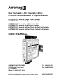
1
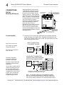
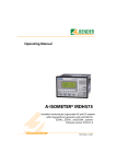
63xT Series AC & DC Powered (4-Wire)
Process Current Isolators w/ Input Excitation
631T-0100 AC Powered Single Current Isolator
631T-0500 DC Powered Single Current Isolator
632T-0100 AC Powered Dual Current Isolator
632T-0500 DC Powered Dual Current Isolator
633T-0100 AC Powered Splitter (Single In/Dual Out) Isolator
633T-0500 DC Powered Splitter (Single In/Dual Out) Isolator
USER’S MANUAL
ACROMAG INCORPORATED
30765 South Wixom Road
P.O. BOX 437
Wixom, MI 48393-7037 U.S.A.
Copyright 2004, Acromag, Inc., Printed in the USA.
Data and specifications are subject to change without notice.
Tel: (248) 624-1541
Fax: (248) 624-9234
8500-736-B05C007
2
Series 631/632/633T User’s Manual
Process Current Isolators
__________________________________________________________________
TABLE OF
CONTENTS
Symbols on equipment:
!
Means “Refer to User’s
Manual (this manual) for
additional information”.
The information of this manual
may change without notice.
Acromag makes no warranty
of any kind with regard to this
material, including, but not
limited to, the implied
warranties of merchantability
and fitness for a particular
purpose. Further, Acromag
assumes no responsibility for
any errors that may appear in
this manual and makes no
commitment to update, or
keep current, the information
contained in this manual. No
part of this manual may be
copied or reproduced in any
form without the prior written
consent of Acromag, Inc.
IMPORTANT SAFETY CONSIDERATIONS
You must consider the possible negative effects of power, wiring,
component, sensor, or software failure in the design of any type of control
or monitoring system. This is very important where property loss or human
life is involved. It is important that you perform satisfactory overall system
design and it is agreed between you and Acromag, that this is your
responsibility.
GETTING STARTED
MOUNTING AND DIMENSIONS………………………
CONTROLS & INDICATORS..…………………………
ISOLATION BARRIERS..……………………………….
CONNECTIONS………………………………………….
DIN-Rail Mounting And Removal………………
Current Input(s)…………………………………...
Current Output(s)..………………………………..
Signal Splitter (633T)……………………………..
Power………………………………………………..
Earth Ground..………………………………….….
CALIBRATION…………………………………………...
Calibration Connections.…………………….….
3
3
3
4
4
4
5
5
6
7
7
7
TECHNICAL REFERENCE
KEY FEATURES…………………………………………
HOW IT WORKS………….……………………………..
Simplified Schematic..…………………………..
SPECIFICATIONS……………………………………….
Model Numbers….………………………………..
Input…………...………………....…………………
Output………………………………………………
Excitation Supply…………………………………
General Specifications…………………………..
Enclosure and Physical………………………….
Environmental……………………………………..
Agency Approvals…..…………………………….
Controls & Indicators…………………………….
8
9
9
10
10
10
10
10
10
11
11
12
12
_______________________________________________________________________________________
Acromag, Inc. Tel:248-624-1541 Fax:248-624-9234 Email:[email protected] http://www.acromag.com
Series 631/632/633T User’s Manual
Process Current Isolators
___________________________________________________________________
TB4
ZERO
TB3
DC-
DC+
36 35 34 33 32 31
TB4
24V+
IN-
IN+
CHAN 2
3.75
(95.3)
SPAN
CL
RTN
OUT-
4.68
(118.9)
PWR
OUT+
46 45 44 43 42 41
CHAN 2
MOUNTING AND
DIMENSIONS
TB3
GND
Acromag
Unit mounts to “T” type DIN
rails (35mm, type EN50022).
POWER
EXC
Units may be mounted sideby-side on 1-inch centers.
Model 632T-0500 Shown
CHAN 1
PWR
EXC
WARNING: IEC Safety
Standards may require that
this device be mounted within
an approved metal enclosure
or sub-system, particularly for
applications with exposure to
voltages greater than or equal
to 75VDC or 50VAC.
OUT-
OUT+
IN-
IN+
CHAN 1
RTN
TB1
2.34
(59.4)
ZERO
24V+
SPAN
11 12 13 14 15 16
TB1
1.05
(26.7)
3.90
(99.1)
"T" RAIL DIN MOUNTING
DIN EN 50022, 35mm
NOTE: Dimensions Are INCHES (MILLIMETERS).
4.35
(110.5)
MODEL 631/632/633T ENCLOSURE DIMENSIONS
TB4
REMOVABLE
(PLUG-IN TYPE)
TERMINAL BLOCKS
CONTROLS &
INDICATORS
TB3
DC+
DC-
GND
24V+
IN+
RTN
Green Power LED (each
channel) is ON if power is on.
POWER
L2
LABELING SHOWN
FOR EACH MODEL
OUT-
IN-
OUT+
Zero Screw (each channel) is
used to calibrate output range
zero endpoint.
633T
CHAN 1
IN+
L1
633T
POWER
OUT-
OUT+
RTN
63xT-0100 (AC)
GND
24V+
IN+
RTN
IN-
OUT+
OUT-
CH 1
24V+
EXC
Span Screw (each channel) is
used to calibrate output range
full-scale endpoint.
631T/632T
11 12 13 14 15 16
INP PWR
(DC Units)
CH2 EXC
INP
CHAN 2
TB3
EXC
DC-
DC+
36 35 34 33 32 31
GND
RTN
24V+
IN-
IN+
46 45 44 43 42 41
TB4
TB4
TB3
CH2
OUTPUT
OUT+
OUT2
24V
DC-DC
24V
EXC SIG1
EXC
XFMR
OUT-
IN-
CHAN 1
OUT+
OUT
11 12 13 14 15 16
ISOLATION BARRIERS
Dashed Lines denote isolation
barriers. AC unit is similar,
except power is connected at
different terminals.
POWER
SIG2 24V
EXC
IN+
EXCITATION SUPPLY IS COMMON TO BOTH CHANNELS BUT SEPARATELY CURRENT LIMITED
TB1
RTN
ZERO
INPUT EXC
EXC
OUTPUT 1 ZERO
& SPAN ADJUST
(15 TURN POTS)
632T
EXC
CH 2
RTN
SPAN
OUTPUT 1 POWER
(GREEN)
TB1
PWR
36 35 34 33 32 31
63xT-0500 (DC)
OUT-
CHAN 1
IN-
CHAN 2
TB1
ZERO
OUT+
OUT-
OUTPUT 2 POWER
(GREEN)
OUTPUT 2 ZERO
& SPAN ADJUST
(15 TURN POTS)
24V+
PWR
SPAN
24V+
CHAN 2
46 45 44 43 42 41
TB3
TB4
Acromag
3
24V
EXC
24V
OUT
POWER
XFMR
ISOLATED
SECONDARIES
631/632/633T
ISOLATION
DIAGRAM
Note unit includes a single
isolated EXC supply with two
24V current-limited outputs.
The input circuit(s), output
circuit(s), excitation, and
power circuit are isolated from
each other for safety and noise
immunity.
TB1
EXC
CH1
INP
CH1
OUTPUT
_______________________________________________________________________________________
Acromag, Inc. Tel:248-624-1541 Fax:248-624-9234 Email:[email protected] http://www.acromag.com
PUSH
MODULE REMOVAL
FROM DIN RAIL
TB3
DC-
DC+
36 35 34 33 32 31
GND
24V+
IN-
IN+
RTN
OUT-
OUT+
CHAN 2
TB4
USE YOUR FINGER TO APPLY
DOWNWARD PRESSURE HERE
AS YOU LIFT AND TILT MODULE
TO REMOVE IT FROM RAIL
46 45 44 43 42 41
POWER
EXC
"T" TYPE
DIN RAIL
Any 63xT Module
EXC
OUT-
IN-
OUT+
CHAN 1
IN+
RTN
DIN-Rail
Mounting & Removal
When attaching the module to the
T-type DIN rail, angle the top of the
unit towards the rail and locate the
top groove of the adapter over the
upper lip of the rail. Firmly push the
unit towards the rail until it snaps into
place. To remove, first separate the
I/O terminal block(s) from the bottom
side of the module to create a
clearance to the DIN mounting area.
Next, while holding the module in
place from above, insert a
screwdriver into the lower arm of the
DIN rail connector and use it as a
lever to force the connector down
until the unit disengages from the rail
(do not twist the screwdriver to avoid
damaging plastic).
24V+
CONNECTIONS
TB1
4
Series 631/632/633T User’s Manual
Process Current Isolators
__________________________________________________________________
11 12 13 14 15 16
Remove Terminal Blocks On This
Side To Provide Clearance
PRY WITH SCREWDRIVER
INSERTED IN SLOT HERE
(DO NOT TWIST TO AVOID
DAMAGING PLASTIC TAB)
PUSH SCREWDRIVER AS SHOWN
TO TILT AND LIFT MODULE OFF RAIL
633T input is connected to
input 2 at TB4.
INPUT CONNECTIONS
TO CURRENT SOURCE
DC
CURRENT
(mA)
TB1
SHIELDED
CABLE
+
-
I
24V+
RTN
EXC
632T inputs are isolated
channel-to-channel.
Connect your DC current input signal to the input terminals as shown
below according to your input source. Repeat this connection for the
second input channel of 632T units at TB4. Use input channel 2 at TB4
when connecting to 633T units.
IN+
INOUT+
CHAN 1
Input is DC current only.
9
16 15 14 13 12 11
Current Input(s)
OUT-
TB1
-
RTN
IN+
INOUT+
OUT-
EXC
24V+
INP1
The excitation supply output is
isolated from the input circuit.
As such, EXC RTN and INmust be jumpered together to
complete the circuit as shown
at right. Do not include the
RTN jumper if an external
excitation supply is used.
2-WIRE
XMTR
TB1
+
OUT1
Excitation supply outputs are
separately current limited to
23mA each.
2-WIRE INPUT TRANSMITTER
CONNECTIONS USING INTERNAL
EXCITATION SOURCE POWER
16 15 14 13 12 11
Two-Wire Transmitter
Connections With Input
Excitation Loop Power.
NOTE 1 TB1
IMPORTANT: REMOVE RTN JUMPER IF AN
EXTERNAL EXCITATION SUPPLY IS USED.
NOTE 1: THIS GROUND CONNECTION IS RECOMMENDED FOR BEST
RESULTS. IF SENSORS ARE INHERENTLY CONNECTED TO GROUND,
USE CAUTION TO AVOID MAKING ADDITIONAL GROUND CONNECTIONS
WHICH COULD GENERATE GROUND LOOPS AND MEASUREMENT ERROR.
_______________________________________________________________________________________
Acromag, Inc. Tel:248-624-1541 Fax:248-624-9234 Email:[email protected] http://www.acromag.com
Series 631/632/633T User’s Manual
Process Current Isolators
___________________________________________________________________
4-WIRE INPUT TRANSMITTER
CONNECTIONS
-
I
NOTE 1
RTN
EXC
24V+
Current Input(s)
IN+
INOUT+
CHAN 1
+
16 15 14 13 12 11
4-WIRE
XMTR
INPUT
CONNECTIONS
TB1
SHIELDED
CABLE
5
Four-Wire Transmitter
Connections
OUT-
TB1
AC POWER
NOTE 1: THIS GROUND CONNECTION IS RECOMMENDED FOR BEST
RESULTS. IF SENSORS ARE INHERENTLY CONNECTED TO GROUND,
USE CAUTION TO AVOID MAKING ADDITIONAL GROUND CONNECTIONS
WHICH COULD GENERATE GROUND LOOPS AND MEASUREMENT ERROR.
Connect your output load to the output terminals as shown below.
Repeat this connection for the second output channel of 632T and 633T
units.
16 15 14 13 12 11
SHIELDED
CABLE
+
R LOAD
DC mA
-
I
24V+
RTN
EXC
TB1
OUTPUT CONNECTIONS
FOR LOADS UP
TO 1000 OHMS
IN+
INOUT+
OUT-
TB1
Signal Splitter (633T)
NOTE: DUAL OUTPUTS OF 633T-0x00 ARE FULLY INDEPENDENT AND ISOLATED
FROM ONE ANOTHER. FOR ANY OUTPUT FAULT CONDITION (OPEN OR SHORT),
THE OPPOSITE OUTPUT AND THE INPUT ARE NOT AFFECTED.
R LOAD
DC mA
-
I
OUT+
OUT-
Model 633T-0x00
(Signal Splitter)
SHIELDED
CABLE
FOR LOADS UP
TO 1000 OHMS
NOTE 1: THIS GROUND CONNECTION IS RECOMMENDED FOR BEST
RESULTS. IF SENSORS ARE INHERENTLY CONNECTED TO GROUND,
USE CAUTION TO AVOID MAKING ADDITIONAL GROUND CONNECTIONS
WHICH COULD GENERATE GROUND LOOPS AND MEASUREMENT ERROR.
INPUT CH 2
EXC
RTN
OUTOUT+
ININ+
RTN
+24V
41 42 43 44 45 46
+
24V+
EXC
NC
TB4
TB1
CH 1
NC
OUTPUT 1 OF 2
TB1
16 15 14 13 12 11
NOTE: 633T-0x00 MODELS
MAY USE ONE OR BOTH
EXCITATION SUPPLY CONNECTIONS.
Current Output(s)
CHAN 1
9
SHIELDED
CABLE
OUTPUT 2 OF 2
I
DC mA
TB4
+
SHIELDED
CABLE
I
RLOAD FOR LOADS UP
TO 1000 OHMS
+
4-WIRE
XMTR
NOTE 1
INPUT
AC POWER
-
_______________________________________________________________________________________
Acromag, Inc. Tel:248-624-1541 Fax:248-624-9234 Email:[email protected] http://www.acromag.com
Power
Voltage Current
(Output/EXC 20mA each)
632/633T-0500 w/EXC
12VDC
419mA
15VDC
317mA
24VDC
179mA
36VDC
121mA
TB3
12 TO 36VDC
+
EARTH
GROUND
631T-0500 w/EXC
12VDC
182mA
15VDC
142mA
24VDC
91mA
36VDC
67mA
TB3
DC+
DC-
INPUT POWER
IS ISOLATED
GND
IMPORTANT (Dual channel 632/633T-0500 models) – If internal
excitation is used, the minimum supply voltage is raised to 15VDC
(“-0500” units) and 100VAC (“-0100” units).
632/633T-0100 w/EXC
125VDC 33mA
115VAC 75mA rms
230VAC 41mA rms
WARNING: DO NOT CONNECT AC POWER TO A DC POWERED
UNIT OR DAMAGE TO THE UNIT WILL OCCUR. Refer to your
module’s label and verify that your model number has a “-0100” suffix
before connecting unit to AC power.
631T-0100 w/EXC
125VDC 18mA
115VAC 42mA rms
230VAC 25mA rms
IMPORTANT – External Fuse, DC Units: If unit is powered from a
supply capable of delivering more than 1A to the unit, it is recommended
that this current be limited via a high surge tolerant fuse rated for a
maximum current of 1A or less (see External Fuse Selection at left).
9
AC Power (“-0100” Units): Connect 90-250V AC or 125V DC±10% to
the power terminals labeled L1 (Hot) & L2 (Neutral). Connect earth
ground to the G (Ground) terminal. Observe proper polarity. For supply
connections, use No. 14 AWG wires rated for at least 75°C.
CAUTION: Do not exceed 250V AC rms.
TB3
90-250VAC
HOT
NEUTRAL
GROUND
TB3
L1
L2
GND
POWER
External Fuse Selection:
Select a time-lag or high surge
tolerant fuse. DC powered
units may be fused with a high
surge tolerant fuse rated for
maximum current of 1A or less
(see Bel Fuse MJS1). AC
powered units may be fused
via a 500mA, 250VAC rated
time-lag fuse (example: Bel
Fuse MRT500, 3JS500, or
equivalent).
DC Power (“-0500” Units): Connect 12-36V DC to the power terminals
labeled DC+ & DC-. Observe proper polarity. For supply connections,
use No. 14 AWG wires rated for at least 75°C.
CAUTION: Do not exceed 36VDC peak.
POWER
9
36 35 34 33 32 31
CONNECTIONS
36 35 34 33 32 31
6
Series 631/632/633T User’s Manual
Process Current Isolators
__________________________________________________________________
INPUT POWER
IS ISOLATED
EARTH
GROUND
CAUTION: Risk of Electric Shock – More than one disconnect switch may
be required to de-energize this equipment before servicing.
_______________________________________________________________________________________
Acromag, Inc. Tel:248-624-1541 Fax:248-624-9234 Email:[email protected] http://www.acromag.com
Series 631/632/633T User’s Manual
Process Current Isolators
___________________________________________________________________
9
Connect Earth Ground as shown in the connection drawings above.
7
Earth Ground
The plastic module housing does not require earth ground.
The ground connections noted are recommended for best results. If
sensors are already grounded, use caution and avoid making additional
ground connections which could create ground loops.
Warning: To comply with safety and performance standards, use
shielded cable and connect earth ground as noted. Failure to use good
wiring and grounding practices may be unsafe and hurt performance.
Calibration is performed as an iterative process of zero and span adjustment
for each output channel. The zero and span adjustment potentiometers are
accessible from the front panel of the unit. Always start by calibrating zero
first, before span. Further, allow the module to warm up a few minutes prior
to calibration. The screwdriver blade used to adjust these pots should not be
more than 0.1 inch (2.54mm) wide.
Equipment Required
• An accurate input current source adjustable for 4 and 20 mA DC.
Surce should be accurate to better than ±0.05% for best results.
• An current or voltage meter accurate to better than ±0.05% is
required to monitor the output level.
• A precision current meter, or a precision load resistance and volt
meter will be needed to monitor the output current for calibration.
Your success in recalibrating the output will strongly depend upon the
accuracy and precision of your signal source and measurement system.
EXAMPLE
CALIBRATION
CONNECTIONS
IMPORTANT: This module
has already been calibrated at
the factory and recalibration is
not normally required, except
as necessary to correct for
long term component aging, or
to satisfy your company’s
maintenance requirements.
Do not attempt to recalibrate
this module unless absolutely
required, as miscalibration will
negatively affect the module’s
performance.
4-20mA
24V+
RTN
EXC
4-20mA
IN+
INOUT+
CHAN 1
16 15 14 13 12 11
TB1
ADJUSTABLE
PRECISION
CURRENT SOURCE
OR CALIBRATOR
OUT-
TB1
DC
CURRENT
METER
CALIBRATION
+
R load
ALTERNATE
CALIBRATION
CONNECTIONS
4-20mA
24V+
RTN
EXC
4-20mA
ADJUSTABLE
PRECISION
CURRENT SOURCE
To help prevent ESD damage
to the circuit, use a grounded
screwdriver to make zero and
span adjustments.
IN+
INOUT+
CHAN 1
16 15 14 13 12 11
TB1
TIP: Verify that current meter
range is properly set to
measure DC current for a 025mA DC range. If no reading
is obtained on current meter,
check that the meter has
power or that its fuse is not
blown.
OUT-
TB1
5-DIGIT
DVM
+
-
R
250
+/-0.1%
_______________________________________________________________________________________
Acromag, Inc. Tel:248-624-1541 Fax:248-624-9234 Email:[email protected] http://www.acromag.com
8
Series 631/632/633T User’s Manual
Process Current Isolators
__________________________________________________________________
CALIBRATION
Adjustment Procedure
1. Connect the input signal and output load as required for the channel
to be calibrated. For dual output 633T units, you may calibrate the
outputs one at a time, without affecting the opposite output.
2. Adjust the input signal to precisely 4.000mA DC (zero). Adjust the
output zero pot until the output reads precisely 4.000 ± 0.008mA DC.
3. Adjust the input signal to precisely 20.000mA DC (full-scale). Adjust
the output span pot until the output reads precisely 20.000 ±
0.008mA DC.
4. Repeat steps 2 & 3 until the readings converge.
5. As a check of calibration, adjust the input signal to precisely
12.000mA and verify the output measurement to within ±0.05% of
span (±0.008mA DC). If the measurement error is greater than
±0.05% of output span, then you should repeat steps 2-4 again until
acceptable accuracy is obtained.
6. Repeat steps 1-5 for the second channel of 632T units, or the
second output of 633T units.
Note: Zero and span pots are
turned clockwise to increase
the output signal, and counterclockwise to reduce the output
signal.
TECHNICAL REFERENCE
KEY FEATURES
•
•
•
•
•
•
•
•
•
•
•
•
Safety Agency Approvals – CE, UL, & cUL listed, plus Class 1;
Division 2; Groups A, B, C, and D approval.
Full Three-Way Galvanic Isolation – Each input channel, each output
channel, the excitation supply, and power are all isolated from each
other for safety and increased noise immunity.
Built-In Excitation Supply – Independently isolated dual output
22V/22mA excitation supply can be used to power one or two 2-wire
transmitters. Excitation outputs are independently current-limited.
Low Input Burden – Less than 1.5V drop for full-scale current
(631/632T units). Less than 3V for 633T signal-splitter units.
Flexible AC or DC Power – Select a 12-36V DC, or universal 90250VAC/125VDC input powered unit. DC powered units are diodecoupled for use with redundant supplies, and/or battery back-up.
Wide 0 to 1000 Ohm Load Range – Can drive 20mA into 1000Ω.
Current Limited Output – Output is safely limited to 27mA.
No Load Trimming Required – You do not have to recalibrate the
output if the load resistance is varied.
Plug-In Terminal Blocks & DIN-Rail Mount - Makes mounting,
removal, and replacement easy.
Hardened For Harsh Environments - For protection from RFI, EMI,
ESD, EFT, & surges. Has low radiated emissions per CE requirements.
Wide Ambient Operation – Reliable over a wide temperature range.
Zero & Span Trim Pots – ±4%, 15-turn trim adjustments for maintaining
long term zero and span calibration and accuracy.
_______________________________________________________________________________________
Acromag, Inc. Tel:248-624-1541 Fax:248-624-9234 Email:[email protected] http://www.acromag.com
Series 631/632/633T User’s Manual
Process Current Isolators
___________________________________________________________________
These isolators isolate one or two DC current input signals according to the
model number, and provide isolated DC current output signal(s) with
adjustable zero and span trim. DC powered units employ a wide input
switching regulator (isolated flyback) to power each output circuit and the
input excitation supply. AC powered units employ a unique universal input
switching circuit to power each output circuit and the excitation supply. A
single isolated excitation supply is shared between both channels, but it has
separate current-limited outputs.
9
HOW IT WORKS
The input circuit employs a unique current transfer circuit that isolates the
signal without generating a large voltage drop. Each input is separately
isolated. An isolated secondary is used to generate an input excitation
supply with dual 24V outputs (23mA each), suitable for powering one or two
2-wire transmitters. Each excitation supply output is current limited to
prevent any short at one channel from pulling down the internal power
supply, or the opposite output. Note that if this supply is shared by both
inputs of dual input units, the resulting circuit is isolated as a group, but not
channel-to-channel.
The isolated current signal is modulated and passed through a high-side
zero and span adjustment circuit that will add or subtract loop current as
required to precisely set the output range. A 24V high-side voltage is used
to drive this circuit which will source 20mA into a load resistance up to
1000Ω. All I/O terminations include filters and transient voltage suppression
to minimize noise and protect the unit from damage due to transients.
Refer to the simplified schematic shown below to help gain a better
understanding of the circuit.
ISOLATED INPUT POWER
(DC POWER SHOWN, AC IS SIMILAR)
12-36VDC (or 90-250VAC)
P
O
W
E
R
24V
SWITCHER
GND
VA
FLTR
THIS GROUND IS
ISOLATED FROM POWER
FOR DC INPUT MODELS
VA
24V
FLTR
VC
+
VB
ISOLATED CH2
OUTPUT POWER
ISOLATED
SECONDARIES
EXCITATION
SUPPLY
ISOLATED EXCITATION
VA
I
N
P
U
T
DC-DC CONV
OUTPUT
POWER
VC
+
LIMITER
FILTER
OSCILLATOR
+
ISOLATED INPUT
LIMITER
PWR
631T CHANNEL SHOWN
632T SIMILARLY ADDS
SECOND I/O CHANNEL
633T UNIT HAS ONE INPUT
DRIVING TWO OUTPUTS
AND IS SIMILAR
+
O
U
T
CURRENT
LIMITER
ZERO/SPAN
ADJUSTMENT
CIRCUIT
Z
REF
S
E
X
C
1
E
X
C
2
63xT SIMPLIFIED
SCHEMATIC
ISOLATED OUTPUT
BIAS
_______________________________________________________________________________________
Acromag, Inc. Tel:248-624-1541 Fax:248-624-9234 Email:[email protected] http://www.acromag.com
10
Series 631/632/633T User’s Manual
Process Current Isolators
__________________________________________________________________
SPECIFICATIONS
These models are DIN-rail mount, DC current input isolators for one or two
input channels, and provide one or two isolated output channels with range
trim adjustment. Units are DC-powered with reverse polarity protection, or
universal AC-powered, and include an isolated input excitation supply with
dual current-limited outputs. The inputs, outputs, excitation, and power
circuits are isolated from each other.
Model Numbers
The model prefix “63xT” denotes the Series 630 I/O Transmitter family. The
“T” suffix denotes Transmitter. The four digit suffix of this model number
represents the following options, respectively: “0” = Default; “1” or “5” =
Universal AC/125VDC, or 12-36VDC Power, respectively; “00” = Default.
631T-0x00 (Single In/Out)
632T-0x00 (Dual In/Dual Out)
633T-0x00 (One In/Dual Out)
Input
One or two input channels for DC current applications only. Input includes
an isolated excitation power supply for powering 2-wire transmitters (see
Connections Section for details).
DC Current: 4 to 20mA DC. IMPORTANT: Input current must not exceed
100mA or damage to the unit may occur. The input to 633T units is
connected at input channel 2.
Input Forward Voltage Drop: Less than 1.5V (1.1V typical) at fullscale (631/632T), or 3V (2.3V typical) at full-scale (633T).
Input Overvoltage Protection: Bipolar Transient Voltage Suppressers
(TVS), 5.6V working, 7.6V clamp level typical.
Input Reverse Polarity Protection: Diode included.
Input Response Time: For a step input, the output reaches 98% of
calibrated span in less than 25ms, typical, with a 500Ω load.
Input Excitation: Isolated 22V DC minimum at 22mA, current limited
near 23mA. See Excitation Supply specification below.
Output
DC Current: 4 to 20mA DC.
Output Limiting: Output is limited to less than 28mA, nominal.
Output Load: 1000Ω minimum (631T); 950Ω minimum (632/633T);
1040Ω typical without excitation load.
Output Ripple: Less than ±0.1% of maximum output span.
Output Load Resistance Effect: Less than ±0.01% of output span
effect for a ±100Ω change in load resistance.
Output Reverse Voltage Protection: Diode included.
Output Trim Range: Zero adjustment to 4mA ±4%, and span
adjustment to 16mA ±4%.
Excitation Supply
May optionally power one or two 2-wire transmitters that may be driving the
isolator input(s). Supply is fully isolated with two separate current-limited
outputs at EXC1 & EXC2 (632T/633T). These outputs are common to each
other and isolated (together) from the input, output, and power circuits.
Voltage: 27-22V range, each (22VDC at 22mA typical).
Current: Current is limited near 23mA, each. Note that EXC voltage will
fold back if load attempts to draw current beyond limit current.
Ripple: 100mVp-p typical.
General
Reference Test Conditions: I/O=4 to 20mA; Load=500Ω; Ambient = 25°C;
Power = 24VDC or 115VAC.
Accuracy: Accuracy is better than ±0.05% of output span, typical. This
includes the effects of repeatability, hysteresis, terminal point linearity,
and adjustment resolution, but does not include sensor error.
_______________________________________________________________________________________
Acromag, Inc. Tel:248-624-1541 Fax:248-624-9234 Email:[email protected] http://www.acromag.com
Series 631/632/633T User’s Manual
Process Current Isolators
___________________________________________________________________
11
Temperature Drift: Better than ±50ppm/°C (±0.005%/°C) over ambient
range. Includes the combined effects of zero & span over temperature.
Bandwidth: -3dB at 50Hz, typical, with a 500Ω load.
Noise Rejection (Normal Mode): -6dB @ 60Hz, typical, with 500Ω load.
Noise Rejection (Common Mode): Better than 100dB at 60Hz, typical.
General
Dimensions: 1.05 inches wide, 4.68 inches tall, 4.35 inches deep. Refer to
the dimensions drawing at the front of this manual.
DIN Rail Mount: Type EN50022; “T” rail (35mm).
I/O Connectors: Removable plug-in type terminal blocks rated for
15A/300V; AWG #12-24 stranded or solid copper wire.
Case Material: Self-extinguishing NYLON type 6.6 polyamide thermoplastic
UL94 V-2, color beige; general purpose NEMA Type 1 enclosure.
Printed Circuit Boards: Military grade FR-4 epoxy glass.
Shipping Weight: 1 pound (0.45 Kg) packed.
Enclosure & Physical
Operating Temperature: -25°C to +75°C (-13°F to +167°F). Dual channel
632/633T units only: If excitation supplies are used, maximum
temperature is derated to +60°C (+140°F).
Storage Temperature: -40°C to +85°C (-40°F to +185°F).
Relative Humidity: 5 to 95%, non-condensing.
Isolation: Each input, each output, excitation supply, & power circuit are
isolated from each other for common-mode voltages up to 250VAC, or
354V DC off DC ground, on a continuous basis (will withstand 1500VAC
dielectric strength test for one minute without breakdown). Complies with
test requirements of ANSI/ISA-82.01-1988 for voltage rating specified.
Installation Category: Designed to operate in an installation in a Pollution
Degree 2 environment with an installation category (over-voltage
category) II rating.
Power Requirements (AC or DC Powered Models): See tables for
current. Data provided with full-scale output (each channel), and
excitation at 20mA (each). If excitation supplies are not used, you can
reduce power consumption up to 30% (AC), or 40% (DC).
Environmental
1
DC-Powered Units: 12-36V DC SELV (Safety Extra Low Voltage) .
Observe proper polarity.
Supply
631T-0500
632/633T-0500
1
12VDC
165mA Typ/182mA Max
381mA Typ/419mA Max
1
15VDC
129mA Typ/142mA Max
288mA Typ/317mA Max
24VDC
83mA Typ/91mA Max
163mA Typ/179mA Max
36VDC
61mA Typ/67mA Max
110mA Typ/121mA Max
1
AC-Powered Units: 90-250VAC or 125VDC±10%.
Supply
125VDC
1
90VAC
115VAC
230VAC
250VAC
631T-0100
16mA Typ/18mA Max
46mA Typ/51mA Max
38mA Typ/42mA Max
23mA Typ/25mA Max
22mA Typ/24mA Max
632/633T-0100
30mA Typ/33mA Max
82mA Typ/90mA Max
68mA Typ/75mA Max
37mA Typ/41mA Max
36mA Typ/40mA Max
CAUTION: Risk of Electric
Shock – More than one
disconnect switch may be
required to de-energize
equipment before servicing.
CAUTION: Do not exceed
36VDC peak, to avoid damage
to the module.
External Fuse (DC): Select a
high surge tolerant fuse rated
for 1A or less to protect unit.
CAUTION: Do not exceed
250Vrms, to avoid damage to
the module.
External Fuse (AC): Select a
time-lag fuse rated for 250VAC
and 500mA to protect unit.
1
Note (Dual channel 632/633T models only): The minimum supply
voltage is raised to 15VDC or 100VAC if excitation supplies are used.
_______________________________________________________________________________________
Acromag, Inc. Tel:248-624-1541 Fax:248-624-9234 Email:[email protected] http://www.acromag.com
12
Series 631/632/633T User’s Manual
Process Current Isolators
__________________________________________________________________
Environmental
These limits represent the
minimum requirements of the
standard, but product has
typically been tested to comply
with higher standards in some
cases.
Electromagnetic Interference Immunity (EMI): Unit has demonstrated a
measurement shift less than ±0.25% of output span with interference
from switching solenoids, commutator motors, and drill motors.
Minimum Immunity Per European Norm EN50082-1:
Electrostatic Discharge (ESD) Immunity: 4KV direct contact and 8KV
air-discharge to the enclosure port per EN61000-4-2.
Radiated Field Immunity (RFI): 10V/M, 80 to 1000MHz AM and
900MHz keyed carrier, per EN61000-4-3 and ENV50204.
Electrical Fast Transient Immunity (EFT): 2KV to power, and 1KV to
signal I/O per EN61000-4-4.
Conducted RF Immunity (CRFI): 10Vrms, 150KHz to 80MHz, per
EN61000-4-6.
Surge Immunity: 0.5KV per EN61000-4-5.
Emissions Per European Norm EN50081-1:
Radiated Frequency Emissions: 30 to 1000MHz per EN55022 Class B.
Electromagnetic Compatibility (EMC) Minimum Immunity Per European Norm EN50082-1:
Electrostatic Discharge (ESD) Immunity: 4KV direct contact and 8KV
air-discharge to the enclosure port per EN61000-4-2.
Radiated Field Immunity (RFI): 10V/M, 80 to 1000MHz AM and
900MHz keyed carrier, per EN61000-4-3 and ENV50204.
Electrical Fast Transient Immunity (EFT): 2KV to power, and 1KV to
signal I/O per EN61000-4-4.
IMPORTANT: Power, input, and output (I/O) wiring must be in accordance
with Class I, Division 2 wiring methods of Article 501-4(b) of the National
Electrical Code, NFPA 70 for installations in the US, or as specified in
section 18-1J2 of the Canadian Electrical Code for installations within
Canada and in accordance with the authority having jurisdiction.
This equipment is suitable for use in Class I, Division 2, Groups A, B,
C, and D, or non-hazardous locations only.
WARNING – EXPLOSION HAZARD – Substitution of components may
impair suitability for Class I, Division 2.
WARNING – EXPLOSION HAZARD – Do not disconnect equipment unless
power has been switched off or the area is known to be non-hazardous.
Agency Approvals
Safety Approvals: CE marked (EMC Directive 89/336/EEC), UL Listed
(UL3121-First Edition, UL1604), cUL Listed (Canada Standard C22.2,
No. 1010.1-92), Hazardous Locations: Class 1; Division 2; Groups A, B,
C, D.
Controls & Indicators
LED Indicators:
PWR (Green) – One per output channel. Constant ON if power is on.
Controls:
Zero Adjust – One per output. A 15-turn potentiometer for making
output zero range adjustments to 4mA ±4% (refer to Calibration).
Span Adjust - One per output. A 15-turn potentiometer for making
output span range adjustments to 16mA ±4% (refer to Calibration).
_______________________________________________________________________________________
Acromag, Inc. Tel:248-624-1541 Fax:248-624-9234 Email:[email protected] http://www.acromag.com