1
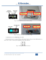
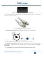
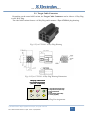
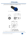
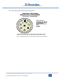
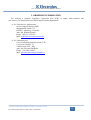
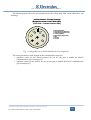
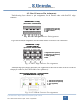
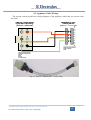
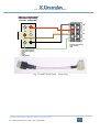
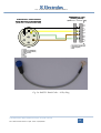
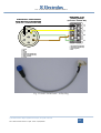
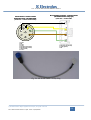
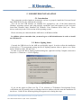
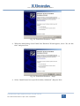
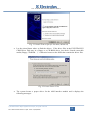
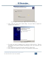
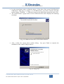
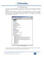
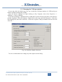
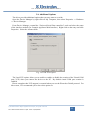
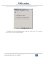
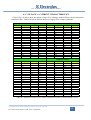
CTI – SOFTWARE DEVELOPMENT GROUP APPLIANCE MINI INTERFACE TECHNICAL GUIDE VERSION 1.0 © 2008 Electrolux Major Appliances Europe, All rights reserved File: AMI Technical Guide v1.pdf - Date: 04/02/2008 CTI – SOFTWARE DEVELOPMENT GROUP TABLE OF CONTENTS 1. INTRODUCTION............................................................................................................... 3 1.1. MAIN FEATURES ..................................................................................................... 4 1.2. ACRONYMS, ABBREVIATIONS, AND REFERENCES ....................................... 5 2. MAIN UNIT ITEMS........................................................................................................... 6 2.1. TARGET CABLE CONNECTOR.............................................................................. 9 3. ORDERING INFORMATION........................................................................................ 12 4. APPLIANCE CABLES .................................................................................................... 13 4.1. MODULE CONNECTOR PIN ASSIGNMENTS .................................................... 13 4.2. BOARD CONNECTOR PIN ASSIGNMENTS ....................................................... 15 4.3. APPLIANCE CABLE WIRINGS ............................................................................. 16 5. USB DRIVERS INSTALLATION .................................................................................. 22 5.1. INTRODUCTION ..................................................................................................... 22 5.2. DRIVER SIGNING ISSUES .................................................................................... 22 5.3. INSTALLING THE DRIVERS ................................................................................ 23 5.4. VERIFYING THE SETUP........................................................................................ 28 5.5. CHANGING THE COM PORT NUMBER.............................................................. 29 5.6. ADDITIONAL OPTIONS ........................................................................................ 30 5.7. UNINSTALLING THE USB DRIVERS .................................................................. 32 6. ELECTRICAL CHARACTERISTICS .......................................................................... 33 6.1. POWER SUPPLY ..................................................................................................... 33 6.2. TYPICAL OUTPUT POWER – ABSOLUTE MAXIMUM RATINGS.................. 33 6.2.1. AMI Power in: ........................................................................................................ 33 6.2.2. AMI Power out: ...................................................................................................... 34 6.3. VOLTAGE VS. CURRENT CHARACTERISTICS ................................................ 35 6.4. CURRENT CHARACTERISTIC ............................................................................. 37 © 2008 Electrolux Major Appliances Europe, All rights reserved File: AMI technical Guide v1.pdf - Date: 04/02/2008 2 CTI – SOFTWARE DEVELOPMENT GROUP 1. INTRODUCTION This document is the technical guide both to the Appliance Mini Interface (AMI) interface module and to he most common Appliance Cables. The AMI is a USB interface module that has been designed by Cross Technology and Innovation (CTI) department in order to suit laboratory and field service applications. The need to have a USB interface module is due to the fact that in the current personal computers the serial port has been replaced by the USB port. Fig. 1. AMI Unit (6-Way Plug Variant) Fig. 2. AMI Unit (8-Way Plug Variant) © 2008 Electrolux Major Appliances Europe, All rights reserved File: AMI technical Guide v1.pdf - Date: 04/02/2008 3 CTI – SOFTWARE DEVELOPMENT GROUP 1.1. MAIN FEATURES The main features of the AMI are the following: • Support of DAAS (Domestic Appliance Acquisition System) and MACS (Major Appliance Communication System) standard communication protocols from Electrolux. DAAS is a pointto-point protocol that allows the communication between an electronic appliance and an external unit. MACS is a peer-to-peer bus protocol that allows the communication among different units both inside and outside an electronic appliance. • Full backward compatibility with the previous DAAS modules from Electrolux. • External power supply (maximum absolute range): from 7.5VDC to 12VDC unregulated. The recommended power supply value is 9VDC unregulated. AMI module automatically uses the external power supply when you connect the corresponding connector. • Output Current: the AMI is able to provide to the target board a regulated 5VDC power supply. This is order to allow the configuration of a board without the need to connect it to the mains power supply. The typical value of the maximum current that you can draw from the interface module depends on whether you use an external power supply or not. If you use an external power supply, the AMI is able to provide up to 150mA (with less than 5% in output voltage drop). If you use instead only the power supply from the USB cable, the AMI is able to provide up to 80mA (with less than 5% in output voltage drop). • USB power capability: if the module is attached to the host PC via the USB cable, in most cases it is not necessary to provide an external power. You must use an external power supply when the target board absorbs more than 80mA. This may be the case when you use the AMI to program a board with several LEDs and/or an LCD display that is not connected to the mains supply (230 VAC). • The AMI module is designed to ensure 3750 VDC isolation between the primary and the secondary stage. The primary stage is the AMI portion that is electrically in contact with the host personal computer. The secondary stage is instead the AMI portion that is electrically in contact with the target electronic board. • AMI units for field service applications are 100% tested for electrical insulation up to 2500 VDC. • The Power LED is green when the module is powered on. If you use an external power supply, you can notice that the green color of the LED is brighter. • The Secondary Power LED is yellow when +5VDC is present on the secondary stage. +5VDC power supply is present in the secondary stage both when you enable it with the secondary power switch and when the AMI is connected to an appliance connected to the mains voltage. • You connect the AMI to the PC using a USB 2.0 male A to male B cable. The maximum length of the cable is 5 meters. However the recommended length is 1.8 meters or less. The longest the USB cable, the highest is the chance of communication errors. This is true especially when you are using the MACS communication protocol. © 2008 Electrolux Major Appliances Europe, All rights reserved File: AMI technical Guide v1.pdf - Date: 04/02/2008 4 CTI – SOFTWARE DEVELOPMENT GROUP • Maximum Output Power that the AMI can provide to the target board: typical 0.74W (@9V power supply, 150 mA output current) • Maximum Input Power that the AMI absorbs from the external power supply: typical 2.6W (@9V power supply, 150 mA output current) • Main Unit Dimensions (width-height-depth): .49.9 x 24.1 x 89.4 mm • Main Unit Weight: about 200g 1.2. ACRONYMS, ABBREVIATIONS, AND REFERENCES AC ACK AMI CTI DAAS DC LCD LED MACS PC SSE USB Alternating Current Appliance Connection Kit Appliance Mini Interface Cross Technology and Innovation Domestic Appliance Acquisition System Direct Current Liquid Crystal Display Light Emitting Diode Major Appliance Communication System Personal Computer Service Support Europe Universal Serial Bus © 2008 Electrolux Major Appliances Europe, All rights reserved File: AMI technical Guide v1.pdf - Date: 04/02/2008 5 CTI – SOFTWARE DEVELOPMENT GROUP 2. MAIN UNIT ITEMS The following figures show the main mechanical elements that make up the AMI: USB Type B Secondary Power Female Connector Switch Secondary Power Main Unit External Power Target Cable Connector Electrolux Power LED LED Target Cable AMI Upper Side View Connector Main Unit Target Cable Secondary Power Switch Target Cable Connector Fig. 3. AMI Items © 2008 Electrolux Major Appliances Europe, All rights reserved File: AMI technical Guide v1.pdf - Date: 04/02/2008 6 CTI – SOFTWARE DEVELOPMENT GROUP USB Type B External Power Female Connector Connector Power LED USB Type B Female Connector Power LED External Power Female Connector AMI Front Side View Fig. 4. AMI Front View from the Primary Stage Secondary Power Target Cable LED Target Cable Secondary Power LED AMI Rear Side View Fig. 5. AMI Rear View from the Secondary Stage A small plastic box is the Main Unit of the AMI. The Main Unit houses a standard USB type B Female Connector (Fig. 6) for the USB interface on the PC side. Table 2.1 lists the pin assignments of the USB connector: Fig. 6. USB Type B Female Connector © 2008 Electrolux Major Appliances Europe, All rights reserved File: AMI technical Guide v1.pdf - Date: 04/02/2008 7 CTI – SOFTWARE DEVELOPMENT GROUP Pin Name Notes 1 VBUS Power 2 DData 3 D+ Data + 4 GND Ground Table 2.1 USB Type B Female Connector Pin Assignment You connect the AMI to the PC using a standard USB cable Male A to Male B. The maximum length of the USB able is 5 meters. Fig. 7. Standard USB Cable Male A to Male B The External Power Connector is a standard male jack connector (2.5 mm diameter): Unregulated 9 – 12 VDC GND Fig. 8. Power Connector The Power LED has only one colour: green when the module is powered on. The External Power LED has only one color: yellow when the +5VDC are present on the secondary stage. To provide +5VDC to the secondary stage it is necessary to activate the Secondary Power Switch. The Target Cable is a shielded cable that connects the AMI to the Appliance Cable. © 2008 Electrolux Major Appliances Europe, All rights reserved File: AMI technical Guide v1.pdf - Date: 04/02/2008 8 CTI – SOFTWARE DEVELOPMENT GROUP 2.1. Target Cable Connector Depending on the actual AMI variant, the Target Cable Connector can be either a 6-Way Plug or an 8-Way Plug. The older AMI variant features a 6-Way Plug and it mounts a Tyco 172339-1 plug housing: Fig. 9. Tyco 172339-1 6-Way Plug Housing Fig. 10. Tyco 172339-1 6-Way Plug Housing Dimensions 6-Way Plug – Male Contacts (Tyco 172339-1 plug housing) (Front View – Contacts Side) 3 2 1 6 5 4 1 Target Device RxD (TxD Host) 2: Target Device TxD (RxD Host) 3: MACS Cable Select 4: GND 5: MACS Signal (single-ended) 6: +5VDC (regulated) Fig. 11. Tyco 172339-1 6-Way Plug Pin Assignments © 2008 Electrolux Major Appliances Europe, All rights reserved File: AMI technical Guide v1.pdf - Date: 04/02/2008 9 CTI – SOFTWARE DEVELOPMENT GROUP The latest AMI version, specifically designed for field service, features an 8-Way Plug with golden contact and it mounts a Bulgin Buccaneer PX041008P plug housing: Fig. 12. Bulgin Buccaneer PX041008P Plug Housing Fig. 13. Bulgin Buccaneer PX041008P Plug Housing Dimensions (mm) viewed from rear panel © 2008 Electrolux Major Appliances Europe, All rights reserved File: AMI technical Guide v1.pdf - Date: 04/02/2008 10 CTI – SOFTWARE DEVELOPMENT GROUP The 8-Way Plug has the following pin assignments: 8-Holes Plug – Male Contacts (Bulgin Buccaneer code PX041008P) (Front View – Contacts Side) 4 3 5 6 8 2 1: MACS Cable Select 2: Target Device TxD (RxD Host) 3: Target Device RxD (TxD Host) 4: +5VDC (regulated) 5: MACS Signal (single-ended) 6: GND 7: not used 8: not used 7 1 Note: the colors of the pins are referred to the internal wires of AMI Fig. 14. Bulgin Buccaneer PX041008P Plug Pin Assignment © 2008 Electrolux Major Appliances Europe, All rights reserved File: AMI technical Guide v1.pdf - Date: 04/02/2008 11 CTI – SOFTWARE DEVELOPMENT GROUP 3. ORDERING INFORMATION For ordering a complete Appliance Connection Kit (ACK), or single AMI modules and accessories, you should turn to the following Electrolux departments: • For Field Service applications: Service Support Europe (SSE) Muggenhofer Straße, 135 D90429 - Nürnberg - Germany Attn. Mr. Wihelm Nießen Phone: +49-911-3231876 Mail: [email protected] • For Laboratory use: Cross Technology and Innovation (CTI) Corso Lino Zanussi, 30 33080 Porcia (PN) - Italy Attn. Mr. Giovanni Dal Bello Phone: +39-0434-394977 Mail: [email protected] © 2008 Electrolux Major Appliances Europe, All rights reserved File: AMI technical Guide v1.pdf - Date: 04/02/2008 12 CTI – SOFTWARE DEVELOPMENT GROUP 4. APPLIANCE CABLES You need an Appliance Cable to complete the connection to the target board. The appliance cable connects the Target Cable Connector to the electronic board: Appliance Mini Interface v3 Appliance Cable Electrolux APPLIANCE BOARD Target Cable Module Board Connector Connector Connector Fig. 15. AMI, Appliance Cable, and Board The ends of the Appliance Cable are the Module Connector and the Board Connector. The Module Connector matches the Target Cable Connector, while the Board Connector plugs into the Appliance Board. 4.1. Module Connector Pin Assignments The following figure provides the pin assignments for the standard 6-Way plug AMI variant (Tyco cap housing): 6-Way Cap – Female Contacts (Tyco 172331-1 cap housing) (Front View – Contacts Side) 1 2 3 4 5 6 1 Target Device RxD (TxD Host) 2: Target Device TxD (RxD Host) 3: MACS Cable Select 4: GND 5: MACS Signal (single-ended) 6: +5VDC (regulated) Fig. 16. Tyco 172331-1 Module Connector Pin Assignment © 2008 Electrolux Major Appliances Europe, All rights reserved File: AMI technical Guide v1.pdf - Date: 04/02/2008 13 CTI – SOFTWARE DEVELOPMENT GROUP The following figure shows the pin assignments for the 8-Way plug AMI variant (Buccaneer cap housing): 8-Holes Socket – Female Contacts (Bulgin Buccaneer code PX041108S) (Front View – Contacts Insertion Side) 5 6 4 3 8 7 1: MACS Cable Select 2: Target Device TxD (RxD Host) 3: Target Device RxD (TxD Host) 4: +5VDC (regulated) 5: MACS Signal (single-ended) 6: GND 7: not used 8: not used 2 1 Fig. 17. Bulgin Buccaneer PX041008S Socket Pin Assignment The actual pins that are used depend on the communication protocol: o appliance cables for the DAAS protocol do not use the pins to handle the MACS communication (pin #1 and pin #5); o appliance cables for the MACS do not use the pins to handle the DAAS communication (pin #2 and pin #3). © 2008 Electrolux Major Appliances Europe, All rights reserved File: AMI technical Guide v1.pdf - Date: 04/02/2008 14 CTI – SOFTWARE DEVELOPMENT GROUP 4.2. Board Connector Pin Assignments The following figure shows the pin assignments for the DAAS cables with RAST2.5 edge connector: EDGE RAST2.5 - 4 way (Lumberg 3521 04) (Front View – Contacts Side) 1: Target Device RxD (TxD Host) 2: Target Device TxD (RxD Host) 3: +5VDC (regulated) 4: GND Fig. 18. RAST2.5 Edge Connector Pin Assignments Fig. 19 shows the pin assignments for the DAAS cables with RAST5 edge connector: EDGE RAST5 - 4 way (Lumberg 3636 04) (Front View – Contacts Side) 1 Target Device RxD (TxD Host) 2: Target Device TxD (RxD Host) 3: +5VDC (regulated) 4: GND Fig. 19. RAST5 Edge Connector Pin Assignments The following figure shows instead the pin assignments for the DAAS cables with JST NVR-04 crimp style connector (for ENV06 fabric care appliances): Disconnectable Connector – Female Contacts (JST NVR-04 female crimp style) (Front View – Contacts Side) 1 Target Device RxD (TxD Host) 2: Target Device TxD (RxD Host) 3: +5VDC (regulated) 4: GND Fig. 20. JST NVR-04 Connector Pin Assignments © 2008 Electrolux Major Appliances Europe, All rights reserved File: AMI technical Guide v1.pdf - Date: 04/02/2008 15 CTI – SOFTWARE DEVELOPMENT GROUP 4.3. Appliance Cable Wirings The current section provides the wiring diagrams of the appliance cables that you can use with the AMI. EDGE RAST2.5 - 4 way (Lumberg 3521 04) (Front View – Contacts Side) 5 4 6 2 1 3 6-Way Cap – Female Contacts (Tyco 172331-1 cap housing) (Front View – Contacts Side) 1 Target Device RxD (TxD Host) 2: Target Device TxD (RxD Host) 3: +5VDC (regulated) 4: GND 1 Target Device RxD (TxD Host) 2: Target Device TxD (RxD Host) 3: not used 4: GND 5: not used 6: +5VDC (regulated) Fig. 21. RAST2.5 DAAS Cable – 6-Way Plug © 2008 Electrolux Major Appliances Europe, All rights reserved File: AMI technical Guide v1.pdf - Date: 04/02/2008 16 CTI – SOFTWARE DEVELOPMENT GROUP 5 4 6 2 1 3 6-Way Cap – Female Contacts (Tyco 172331-1 cap housing) (Front View – Contacts Side) 1 Target Device RxD (TxD Host) 2: Target Device TxD (RxD Host) 3: +5VDC (regulated) 4: GND 1 Target Device RxD (TxD Host) 2: Target Device TxD (RxD Host) 3: not used 4: GND 5: not used 6: +5VDC (regulated) Fig. 22. RAST5 DAAS Cable – 6-Way Plug © 2008 Electrolux Major Appliances Europe, All rights reserved File: AMI technical Guide v1.pdf - Date: 04/02/2008 17 CTI – SOFTWARE DEVELOPMENT GROUP Disconnectable Connector – Female Contacts (JST NVR-04 female crimp style) (Front View – Contacts Side) 5 4 6 2 1 3 6-Way Cap – Female Contacts (Tyco 172331-1 cap housing) (Front View – Contacts Side) 1 Target Device RxD (TxD Host) 2: Target Device TxD (RxD Host) 3: +5VDC (regulated) 4: GND 1 Target Device RxD (TxD Host) 2: Target Device TxD (RxD Host) 3: not used 4: GND 5: not used 6: +5VDC (regulated) Fig. 23. JST DAAS Cable – 6-Way Plug © 2008 Electrolux Major Appliances Europe, All rights reserved File: AMI technical Guide v1.pdf - Date: 04/02/2008 18 CTI – SOFTWARE DEVELOPMENT GROUP 8-Holes Socket – Female Contacts (Bulgin Buccaneer code PX041108S) (Front View – Contacts Insertion Side) 5 EDGE RAST2.5 - 4 way (Lumberg 3521 04) (Front View – Contacts Side) 4 6 3 8 7 2 1 1: Target Device RxD (TxD Host) 2: Target Device TxD (RxD Host) 3: +5VDC (regulated) 4: GND 1: not used 2: Target Device TxD (RxD Host) 3: Target Device RxD (TxD Host) 4: +5VDC (regulated) 5: not used 6: GND 7: not used 8: not used Fig. 24. RAST2.5 DAAS Cable – 8-Way Plug © 2008 Electrolux Major Appliances Europe, All rights reserved File: AMI technical Guide v1.pdf - Date: 04/02/2008 19 CTI – SOFTWARE DEVELOPMENT GROUP 8-Holes Socket – Female Contacts (Bulgin Buccaneer code PX041108S) (Front View – Contacts Insertion Side) 5 EDGE RAST5 - 4 way (Lumberg 3636 04) (Front View – Contacts Side) 4 6 3 8 7 2 1 1: not used 2: GND 3: not used 4: not used 5: Target Device TxD (RxD Host) 6: Target Device RxD (TxD Host) 7: +5VDC (regulated) 8: not used 1 Target Device RxD (TxD Host) 2: Target Device TxD (RxD Host) 3: +5VDC (regulated) 4: GND Fig. 25. RAST5 DAAS Cable – 8-Way Plug © 2008 Electrolux Major Appliances Europe, All rights reserved File: AMI technical Guide v1.pdf - Date: 04/02/2008 20 CTI – SOFTWARE DEVELOPMENT GROUP 8-Holes Socket – Female Contacts (Bulgin Buccaneer code PX041108S) (Front View – Contacts Insertion Side) 5 Disconnectable Connector – Female Contacts (JST NVR-04 female crimp style) (Front View – Contacts Side) 4 6 3 8 7 2 1 1: not used 2: GND 3: not used 4: not used 5: Target Device TxD (RxD Host) 6: Target Device RxD (TxD Host) 7: +5VDC (regulated) 8: not used 1 Target Device RxD (TxD Host) 2: Target Device TxD (RxD Host) 3: +5VDC (regulated) 4: GND Fig. 26. JST DAAS Cable – 8-Way Plug © 2008 Electrolux Major Appliances Europe, All rights reserved File: AMI technical Guide v1.pdf - Date: 04/02/2008 21 CTI – SOFTWARE DEVELOPMENT GROUP 5. USB DRIVERS INSTALLATION 5.1. Introduction This paragraph provides hands-on instructions on how to properly install the Universal Serial Bus (USB) drivers for the AMI interface module. You can use the USB interface on standard PCs equipped by one of the latest Microsoft Windows operating systems with plug-and-play capabilities and with support for the Universal Serial Bus: Windows 2000, Windows XP, Windows Vista, Windows Server 2003, etc. These drivers work only in the 32-bit version of the operating system. Please note that you cannot install the AMI drivers in Windows 98/Me. In addition, please remember that you must log on as full Administrator in order to install the USB drivers. 5.2. Driver Signing Issues Currently the USB drivers for the AMI are not digitally signed. In order to allow the installation of the drivers, CTI recommends setting the Driver Signing Options either to Ignore or to Warn both in Windows 2000, XP and Vista. In order to open the Driver Signing Options dialog box, right click on My Computer, then select Properties >> Hardware >> Driver Signing: Fig. 27. Driver Signing Options If you set the option to Warn (see Fig. 27 for reference), CTI-Software Development Group verified that only XP actually issues a warning to the user whenever he/she starts the installation of the drivers. Under XP the following dialog box appears twice during the setup: © 2008 Electrolux Major Appliances Europe, All rights reserved File: AMI technical Guide v1.pdf - Date: 04/02/2008 22 CTI – SOFTWARE DEVELOPMENT GROUP Fig. 28. Driver Signing Warning in XP In this case you should just select Continue Anyway and ignore the above message. Under Vista instead, you see a dialog box that displays the following message: “Windows can’t verify the publisher of this driver software”. In this case you can safely issue the “Install this driver software anyway” command. Currently CTI-Software Development Group does not yet know whether in the future it will certify or not the USB drivers for the appliance adapters. 5.3. Installing the drivers The instructions that follow in this paragraph refer to Windows XP Professional Service Pack 2 – English Version. Other versions of this operating system may require slightly different commands. Although Windows 2000 and Vista require different steps, the general concepts still apply. For this reason you can refer to this section also if you are using Windows 2000 and Vista. If you use the AMI for the first time, you need the files of the ELECTROLUX CDM Driver Disk. To install them you should follow the next simple steps (if you experience a problem please refer to the next paragraph on “driver signing” issues): • Connect the AMI to the PC by means on a type A-B (male/male) USB cable. • Wait for the plug-and-play (PnP) manager to detect the new hardware. You should see the following message: © 2008 Electrolux Major Appliances Europe, All rights reserved File: AMI technical Guide v1.pdf - Date: 04/02/2008 23 CTI – SOFTWARE DEVELOPMENT GROUP Fig. 29. Found New Hardware – Step1 • When the initial dialog of the Found New Hardware Wizard appears, select “No, not this time” and press Next. Fig. 30. Found New Hardware – Step2 • Select “Install from a list or specific location (Advanced)” and press Next. © 2008 Electrolux Major Appliances Europe, All rights reserved File: AMI technical Guide v1.pdf - Date: 04/02/2008 24 CTI – SOFTWARE DEVELOPMENT GROUP Fig. 31. Install From a Specific Location (Advanced) • Let the wizard know where to find the drivers. If the driver files in the ELECTROLUX CDM Driver Disk stay in a floppy or a CD-ROM drives, just check “Search removable media (floppy, CD-ROM…)”. Otherwise browse to the folder that contains the driver files. Fig. 32. Locate Driver Files • The system locates a proper driver for the AMI interface module and it displays the following messages: © 2008 Electrolux Major Appliances Europe, All rights reserved File: AMI technical Guide v1.pdf - Date: 04/02/2008 25 CTI – SOFTWARE DEVELOPMENT GROUP Fig. 33. Appliance Mini Interface Adapter Driver Files Search Results • After a while, the system shows another dialog. installation of the USB drivers. Just press Finish to complete the Fig. 34. Setup End • • • The system now detects an additional piece of hardware (USB Serial Port). When the initial dialog of the Found New Hardware Wizard appears, select “No, not this time” and press Next. Select “Install from a list or specific location (Advanced)” and press Next. Select “Search for a suitable driver for my device (recommended)” and press Next. © 2008 Electrolux Major Appliances Europe, All rights reserved File: AMI technical Guide v1.pdf - Date: 04/02/2008 26 CTI – SOFTWARE DEVELOPMENT GROUP • • Let the wizard know where to find the drivers. If the driver files in the ELECTROLUX CDM Driver Disk stay in a floppy or a CD-ROM drives, just check “Search removable media (floppy, CD-ROM…)”. Otherwise browse to the folder that contains the driver files. The system locates a proper driver for the USB Serial Port and it displays the following messages: Fig. 35. USB Serial Port Driver Files Search Results • After a while, the system shows another dialog. installation of the virtual COM port driver. Just press Finish to complete the Fig. 36. Setup End © 2008 Electrolux Major Appliances Europe, All rights reserved File: AMI technical Guide v1.pdf - Date: 04/02/2008 27 CTI – SOFTWARE DEVELOPMENT GROUP 5.4. Verifying the setup In order to verify the installation of the USB drivers and the correct operation of the plug-andplay features, right click on My Computer, then select Properties >> Hardware >> Device Manager. When the interface module is connected to the PC through the USB cable, the Device Manager should display two entries showing the name of the interface module: one under “Ports (COM & LPT)” and the other under “Universal Serial Bus controllers”. For example if the “Appliance Universal Adapter” is connected: Fig. 37. Device Manager Then verify that these entries disappear if you disconnect the interface module. Finally check that these entries appear if you turn on or connect again the module. © 2008 Electrolux Major Appliances Europe, All rights reserved File: AMI technical Guide v1.pdf - Date: 04/02/2008 28 CTI – SOFTWARE DEVELOPMENT GROUP 5.5. Changing the COM port number If you want, after the initial setup, you can override the COM port number of a USB serial port that the installer automatically assigns. Open the Device Manager by right clicking on My Computer, then select Properties >> Hardware >> Device Manager. From Device Manager, expand the Ports (COM & LPT) node and select the name of the interface module (Appliance Universal Adapter). Right-click on the entry and click Properties. Select the Port Settings tab, then click Advanced. Choose the required COM port number from the list and click OK. Fig. 38. COM Port Number Selection You are recommended not to change any other options in this dialog. © 2008 Electrolux Major Appliances Europe, All rights reserved File: AMI technical Guide v1.pdf - Date: 04/02/2008 29 CTI – SOFTWARE DEVELOPMENT GROUP 5.6. Additional Options The driver provides additional options that you may want to override. Open the Device Manager by right click on My Computer, then select Properties >> Hardware >> Device Manager. From Device Manager, expand the “Universal Serial Bus controllers” node and select the name of the interface module (for example Appliance Mini Interface). Right click on the entry and click Properties. Select the Advanced tab: Fig. 39. Load VCP Option The Load VCP option, allows you to enable or enable or disable the creation of the Virtual COM port (VCP) when you connect the device to the PC. By default virtual COM port creation is enabled. Please remember that VCP support is essential when you use the Electrolux DAAS protocol. For this reason, CTI recommends you to leave this option set. © 2008 Electrolux Major Appliances Europe, All rights reserved File: AMI technical Guide v1.pdf - Date: 04/02/2008 30 CTI – SOFTWARE DEVELOPMENT GROUP If you select the Power Management tab, you can override the installation defaults: Fig. 40. Power Management Options The default settings for Power Management are already OK. For this reason, CTI recommends you to leave these options in their default state. © 2008 Electrolux Major Appliances Europe, All rights reserved File: AMI technical Guide v1.pdf - Date: 04/02/2008 31 CTI – SOFTWARE DEVELOPMENT GROUP 5.7. Uninstalling the USB Drivers In order to remove the USB drivers of the AMI disconnect it from the PC and then launch the Control Panel and select the Add/Remove Programs applet. Then locate the “FTDI USB Serial Converter Drivers” entry and remove the corresponding software: Fig. 41. Removing the USB Drivers Sometimes the “Add/Remove Programs” utility doesn’t work correctly and the drivers are not removed from the system. To solve this problem you can use the FTClean utility provided by the FTDI. company. You can download the latest version of the FTClean utility from this URL: http://www.ftdichip.com/Resources/Utilities.htm. © 2008 Electrolux Major Appliances Europe, All rights reserved File: AMI technical Guide v1.pdf - Date: 04/02/2008 32 CTI – SOFTWARE DEVELOPMENT GROUP 6. ELECTRICAL CHARACTERISTICS This chapter provides detailed information about the typical electrical characteristics of the AMI module. CTI performed the electrical characterization on an AMI version 3 module with 8-Way plug. Please remember that the actual characteristics may slightly change among different samples. 6.1. POWER SUPPLY The maximum absolute range for the external power supply is from 7.5VDC to 12VDC unregulated. The recommended power supply value is 9VDC unregulated. AMI module automatically uses the external power supply when you connect the corresponding connector. 6.2. TYPICAL OUTPUT POWER – Absolute maximum ratings AMI is able to provide to the target board a regulated +5VDC power supply. The maximum current that is possible to absorb from the interface is determined by AMI internal circuit and power supply mode: External power supply: MAX253 maximum power consumption, LM340MP-5 and LE50ABZ output current limit values like explained hereafter. 6.2.1. AMI Power in: LM340MP-5 (National Semiconductor) voltage regulator: package SOT-223. parameters: • • • • • Datasheet TJ range : 0 ÷125 °C TA range : 0 ÷125 °C Thermal shutdown occurs if TDIE > 150°C Input voltage required to maintain line regulation: minimum 7.5V (@TJ = 25°C, IO <1A) for VOUT=+5V and VIN=+10V (nominal). So this value cannot be considered valid in general but may vary depending on test situation or sample under test The maximum allowable power dissipation at any ambient temperature is a function of the maximum junction temperature for operation (here TJMAX = 125°C), the junction-toambient thermal resistance (θJA), and the ambient temperature (TA) according to: ( T -T ) PDMAX = JMAX A θ JA If this dissipation is exceeded, the die temperature will rise above TJMAX and the electrical specifications do not apply • If SOT-223 is used, the junction-to-ambient thermal resistance θJA is 174°C/W • It’s supposed a standard TA of 25°C © 2008 Electrolux Major Appliances Europe, All rights reserved File: AMI technical Guide v1.pdf - Date: 04/02/2008 33 CTI – SOFTWARE DEVELOPMENT GROUP The maximum power dissipation for this component can be therefore calculated under the above mentioned conditions that is PDMAX=0.574W. Then maximum output current for different values of VIN can be listed, considering a gain factor g=0.8: VIN 7.5V 9V 12V ΔV to 5V 2.5V 4V 7V Table 6.1 PDMAX g ⋅ ΔV 287mA 179mA 102mA IOUT_MAX = MAX253CSA+ (Maxim) power-driver designed to provide isolated power to the circuit. Datasheet parameters: • • • TJ max : 150 °C TA range : 0 ÷70 °C The maximum allowable power dissipation is 1W 6.2.2. AMI Power out: LE50ABZ (STM) fixed positive voltage regulator. Datasheet parameters: • • • • Output current limit : 150mA min TJ range : -40 ÷125 °C TA range : -40 ÷125 °C Dropout voltage (@IO = 100 mA): typ. 0.2V Summarizing, output current limit is fixed to 150mA given by LE50ABZ. Above this value, and particularly for external +12V supply, power consumption of LM340MP-5 rises over PDMAX with a consequent increase of junction temperature even up to TJMAX causing component thermal shutdown; for example if Iout=200mA and Vin=12V, PD=1.12W, 546mW above calculated limit. PC laptop supplied by battery (+5V [VCC] tolerance is ±5%) like worst case for USB AMI feeding. Like in the situation explained previously LE50ABZ limits output current value to 150mA. Above this value output voltage falls down drastically like displayed in Table 6.2 and chart in Fig. 32 due to “not stabilized” +5V voltage supplied by laptop battery. © 2008 Electrolux Major Appliances Europe, All rights reserved File: AMI technical Guide v1.pdf - Date: 04/02/2008 34 CTI – SOFTWARE DEVELOPMENT GROUP 6.3. VOLTAGE vs. CURRENT CHARACTERISTICS Chart in Fig. 42 shows how the output voltage (Vout) changes under different current absorption conditions (Iout). Different curves indicate the power supply (Vin) voltage conditions. Condition 1: external power supply 7.5V Iout [mA] Vout [V] Iin [mA] Vin Condition 2: external power supply 9V Vin Iout [mA] Vout [V] Iin [mA] 7.36V 9V 0 10 20 30 40 50 60 70 80 90 100 120 140 150 160 170 180 190 200 5.02 5.01 4.99 4.987 4.977 4.968 4.955 4.94 4.93 4.92 4.9 4.88 4.85 4.84 4.7 4.69 4.52 4.47 4.31 79.4 95.8 110 124 139 152 165 178 192 206 219 246 276 289 302 316 331 343 357 Condition 3: external power supply 12V Vin Iout [mA] 11.9V Vout 0 10 20 30 40 50 60 70 80 90 100 120 140 150 160 170 180 190 200 5.02 5.01 5 4.99 4.98 4.97 4.96 4.95 4.94 4.93 4.92 4.89 4.87 4.91 4.9 4.81 4.57 4.4 4.16 86.8 100 113 127 141 155 169 181 195 209 222 249 276 288 300 316 332 345 360 Iin [mA] Condition 4: USB power supply 5V (laptop supplied by battery) Vin Iout [mA] Vout Iin [mA] 5.11V 0 5.02 88 0 5.016 101 10 5.01 100 10 5.007 113 20 5 114 20 4.996 126 30 4.99 127 30 4.986 139 40 4.98 141 40 4.97 151 50 4.96 154 50 4.96 165 60 4.96 168 60 4.95 177 70 4.946 182 70 4.94 190 80 4.93 195 80 4.86 203 90 4.92 210 90 4.71 216 100 4.91 223 100 4.52 229 120 4.88 250 120 4.127 253 140 4.86 277 140 3.706 285 150 4.85 289 150 3.47 298 160 4.7 305 160 3.21 309 170 4.4 318 170 2.9 322 180 4.45 332 180 2.52 333 190 4.2 346 190 1.96 343 200 4.05 359 200 0.5 343 Table 6.2 Measured values of Vout and Iin @ different values of output (load) current © 2008 Electrolux Major Appliances Europe, All rights reserved File: AMI technical Guide v1.pdf - Date: 04/02/2008 35 CTI – SOFTWARE DEVELOPMENT GROUP AMI v3 ouput signals 6 5 Vout [V] 4 3 2 1 0 0 10 20 30 40 50 60 70 80 90 100 120 140 150 160 170 180 190 200 Iout [mA] Vin:7.5V Vin:9V Vin:12V Vin from USB:5V Fig. 42. Vout trend for different values of Iout and for different Vin – note that Iout maximum to have a stable Vout is 150mA in agreement with LE50ABZ parameters above if external power supply is provided, about 100mA for USB power supply © 2008 Electrolux Major Appliances Europe, All rights reserved File: AMI technical Guide v1.pdf - Date: 04/02/2008 36 CTI – SOFTWARE DEVELOPMENT GROUP 6.4. CURRENT CHARACTERISTIC Chart in Fig. 43 displays how the power supply current (Iin) absorbed by the AMI changes under different load conditions (Iout). AMI v3 input current vs output current 400 350 300 Iin [V] 250 200 150 100 50 0 0 10 20 30 40 50 60 70 80 90 100 120 140 150 160 170 180 190 200 Iout [mA] Vin:7.5V Vin:9V Vin:12V Vin from USB:5V Fig. 43. Nearly linear ratio between Iout and Iin for different conditions of power supply © 2008 Electrolux Major Appliances Europe, All rights reserved File: AMI technical Guide v1.pdf - Date: 04/02/2008 37