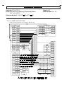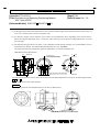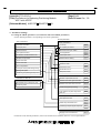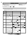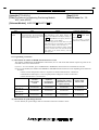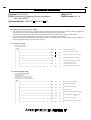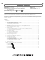
1
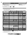
TECHNICAL BULLETIN
[Issue No.] T12-0015-A
[Title] Procedures for Replacing Positioning Module
AD71 with AD75P
[Page] 1/39
[Date of Issue Oct., ‘03
[Relevant Models] A1SD75P -S3/AD75P -S3
Thank you for your continued support of Mitsubishi programmable logic controllers, MELSEC-A series.
This bulletin is written for those intending to replace the AD71/A1SD71 positioning module with the AD75P/ A1SD75P,
including relevant information such as specification changes, method of replacement and recommended equipment such as
connectors, cables, etc.
Contents
Introduction .........................................................................................................................................................2
1. Functional comparison between AD71 and AD75 ........................................................................................3
1.1 Table of functional comparisons ..........................................................................................................3
1.2 Replacement procedure flowchart ........................................................................................................4
2. Rewiring ........................................................................................................................................................5
2.1 Comparison between AD71 and AD75P for connecting the signal cable ............................................5
2.2 Servo amplifier connection example.....................................................................................................6
3. Parameter settings .........................................................................................................................................9
3.1 Setting the AD75P parameters (Correlation of AD71 and AD75P parameters) ..................................9
3.2 AD75P zero point return parameter setting ........................................................................................ 13
4. Positioning data settings .............................................................................................................................. 15
4.1 AD75P positioning data setting ......................................................................................................... 15
4.2 Number of positioning data ................................................................................................................ 17
5. Data for positioning control start ................................................................................................................ 18
6. OS data area (Including monitor information) ............................................................................................ 22
7. Positioning control program ........................................................................................................................ 23
7.1 Differences in I/O signals ................................................................................................................... 23
7.2 Precautions for replacing AD71 with AD75P .................................................................................... 24
7.3 Programming restrictions ................................................................................................................... 25
7.4 Ladder program examples for AD75P ............................................................................................... 26
8. AD75P operation test .................................................................................................................................. 32
Appendix
Tables of AD75P buffer memory addresses ................................................................................... 33
(1) Parameter Pr ....................................................................................................................................... 33
(2) Monitor data Md ................................................................................................................................ 35
(3) Control data Cd .................................................................................................................................. 37
(4) Positioning data Da ............................................................................................................................ 38
HEAD OFFICE : 1-8-12, OFFICE TOWER Z 14F HARUMI CHUO-KU 104-6212, JAPAN
NAGOYA WORKS : 1-14, YADA-MINAMI 5-CHOME, HIGASHI-KU, NAGOYA, JAPAN
TECHNICAL BULLETIN
[Issue No.] T12-0015-A
[Title] Procedures for Replacing Positioning Module
AD71 with AD75P
[Page] 2/39
[Date of Issue Oct., ‘03
[Relevant Models] A1SD75P -S3/AD75P -S3
Introduction
The performance of the AD75P is improved compared to the AD71, as explained below:
(1) Reduced start processing time
(a) With the addition of enhanced high-speed processing, the start processing time for "positioning control start" is
reduced to 20ms.
(Compared to the AD71, the maximum processing times for independent positioning and for interpolation
positioning are 58ms and 94ms respectively.)
(2) Easier maintenance
(a) Positioning data and parameter settings are stored in the AD75P flash ROM; therefore data can be retained without
the need for batteries.
(b) The 17-segment display provides a visual means for checking errors or input signals.
(c) The history function enables checking of historical data such as start, errors or warning data.
When using the AD75P, it is recommended to also obtain the "GX Configurator-AP" configuration software package.
This software provides an easier method to reconfigure positioning data, debug the positioning control system, etc.
In this bulletin, the module names are referred to as shown in the table below.
Generic term
AD71
AD71S2
AD71S7
AD75P
Model Name
AD71, AD71S1, AD71S2, AD71S7, A1SD71-S2, A1SD71-S7
AD71S2, A1SD71-S2
AD71S7, A1SD71-S7
AD75P1-S3, AD75P2-S3, AD75P3-S3, A1SD75P1-S3, A1SD75P2-S3, A1SD75P3-S3
HEAD OFFICE : 1-8-12, OFFICE TOWER Z 14F HARUMI CHUO-KU 104-6212, JAPAN
NAGOYA WORKS : 1-14, YADA-MINAMI 5-CHOME, HIGASHI-KU, NAGOYA, JAPAN
TECHNICAL BULLETIN
[Issue No.] T12-0015-A
[Title] Procedures for Replacing Positioning Module
AD71 with AD75P
[Page] 3/39
[Date of Issue Oct., ‘03
[Relevant Models] A1SD75P -S3/AD75P -S3
1. Functional comparison between AD71 and AD75P
1.1 Table of functional comparisons
The following table shows functional comparisons between the AD71 and AD75P. For programs, refer to Chapter 7.
: Compatible (no restrictions), : Compatible (with restrictions), : No alternative
Function
No. of control axes
Manual pulse generator operation *1
Applicable manual pulse
generator
AD71
AD71S2
AD71S7
AD71
AD71S1
A1SD71-S2 A1SD71-S7
2 axes
Available
Available
−
HD52B (Mitsubishi Electric Corp.),
OSM-01-2(C) (Nemicon).
Position control
mode
Positioning
JOG operation
Zero point return
1-time positioning (End)
Available
n-time positioning
(Continued)
Available
Continue positioning,
while changing speed
(Pattern change)
Linear interpolation
Speed/Position control
switching mode
Speed control mode
No. of positioning data
Available
Available
(continuous path)
Available
Available
−
Available
−
Available
−
Available
400/axis
−
Available
600/axis
Individual setting for
Accel./Decel. time
(4 patterns for each)
Available
N/A
Available
N/A
Flash ROM
(without battery)
Acceleration/Deceleration time
Same for Accel. and Decel. times (1 pattern)
Backlash compensation
Error compensation
M code
M code comment display
Available
Available
Available
Available
Data storage
SRAM (with battery backup)
No. of occupied slots
I/O signal lines
Available
Available
32 points/slot
Upper/Lower limit switch signal
(FLS/RLS input signal)
Other signals
Current consumption
AD71S2, AD71S7
: 32 points/slot
A1SD71-S2, A1SD71-S7
: 48 points/2 slots
32 points/slot
N/A
START signal (Output signal)
Pulse output (Output signal)
AD75P
AD75P2-S3
A1SD75P2-S3
2 axes
Available
MR-HDP01
(Mitsubishi Electric
Corp.)
Available
Available
Available
(independent
positioning)
Available
(continuous
positioning)
Open
collector
Available
Differential
Open collector
driver
Available
1.5A (0.8A for A1SD71-S2/S7)
Available
N/A
Open collector/
Differential driver
Available
0.7A
Compatibility
Usable products are
different between
AD71 and AD75P.
*2
*3
*4
External wiring is
required for
AD75P.
−
*1: By setting Manual pulse generator selection parameter Pr.23 , 2-axis operation with a manual pulse generator is available for the AD75P.
For further details, refer to Section 5.2.3 “Detailed parameters” of the AD75P User’s Manual.
*2: The AD75P substitutes electronic gears.
*3: No. of writes to flash ROM is up to 100,000.
*4: When replacing the A1SD71-S2 or A1SD71-S7, mount a blanking module in the empty slot.
HEAD OFFICE : 1-8-12, OFFICE TOWER Z 14F HARUMI CHUO-KU 104-6212, JAPAN
NAGOYA WORKS : 1-14, YADA-MINAMI 5-CHOME, HIGASHI-KU, NAGOYA, JAPAN
TECHNICAL BULLETIN
[Issue No.] T12-0015-A
[Title] Procedures for Replacing Positioning Module
AD71 with AD75P
[Page] 4/39
[Date of Issue Oct., ‘03
[Relevant Models] A1SD75P -S3/AD75P -S3
1.2 Replacement procedure flowchart
This flow chart shows the procedures to replace the AD71 with the AD75P. This bulletin provides relevant
explanations in the order shown below.
<Reference section>
Disconnect the wiring for
AD71 and rewire for AD75P.
Rewrite the parameter data
for AD75P.
2.1 Comparison between AD71 and AD75P for connecting the signal cable
2.2 Servo amplifier connection example
3.1 Setting the AD75P parameters
3.2 AD75P zero point return parameter setting
4.1 AD75P positioning data setting
Rewrite the positioning data
for AD75P.
Rewrite the ladder program
for AD75PD
Perform an operation test
using the JOG function.
5
Data for positioning control start
6
OS data area
7.1 Differences in I/O signals
7.2 Precautions for replacing AD71 with AD75P
7.3 Programming restrictions
8
AD75P operation test
HEAD OFFICE : 1-8-12, OFFICE TOWER Z 14F HARUMI CHUO-KU 104-6212, JAPAN
NAGOYA WORKS : 1-14, YADA-MINAMI 5-CHOME, HIGASHI-KU, NAGOYA, JAPAN
TECHNICAL BULLETIN
[Issue No.] T12-0015-A
[Title] Procedures for Replacing Positioning Module
AD71 with AD75P
[Page] 5/39
[Date of Issue Oct., ‘03
[Relevant Models] A1SD75P -S3/AD75P -S3
2. Rewiring
2.1 Comparison between AD71 and AD75P for connecting the signal cable
AD71
AD71
Signal cable
AD75P
Driver X Axis
AD75
P1
Signal cable
Driver Axis 1
1-axis control
AD71 signal connector (40-pin) is usable
for X and Y axes.
AD71
Signal cable
2-axis control
Signal cable
Connector type*1
Driver X Axis
Driver Y Axis
AD75P signal connector (36-pin) is
separate for each axis. (One-to-one
connection cable to the driver)
AD75
P2
Signal cable
Signal cable
Driver Axis 1
Driver Axis 2
AD71 signal connector (40-pin) is usable
for X and Y axes (Bifurcated type cable).
AD75P signal connector (36-pin) is
separate for each axis. (Straight pin-to-pin
connection type cable to the driver)
Connector
Set: A6CON
Connector cover
Manufacturer: Mitsubishi Electric Corp.
Connector: 10136-3000VE
Connector cover: 10336-56F0-008
Manufacturer: Sumitomo 3M Ltd.
)
*1: The connector is included with both the AD71 and AD75P.
New signal cables are required for the AD75P, as the connector shape for the external signal connection and signal
specifications are different from the AD71. The following dedicated cables are available for connecting the AD75P to
the servo amplifier (please use the correct cable corresponding to the servo amplifier used).
<Dedicated cable>
Module
AD75P
Servo amplifier
MR-J A
MR-H A(N)
MR-MR-J2(S) - A
MR-C A
Applicable cable
AD75C20SJ
AD75C20SH
AD75C20SJ2
AD75C20SC
HEAD OFFICE : 1-8-12, OFFICE TOWER Z 14F HARUMI CHUO-KU 104-6212, JAPAN
NAGOYA WORKS : 1-14, YADA-MINAMI 5-CHOME, HIGASHI-KU, NAGOYA, JAPAN
TECHNICAL BULLETIN
[Issue No.] T12-0015-A
[Title] Procedures for Replacing Positioning Module
AD71 with AD75P
[Page] 6/39
[Date of Issue Oct., ‘03
[Relevant Models] A1SD75P -S3/AD75P -S3
2.2 Servo amplifier connection example
Connection example with the servo amplifier (MR-H-A(N))
AD75
(1)
(2)
(2)
Differential driver
FLS
12
12
PULSE F+ 3 3
RLS
13
13
PULSE F- 21 21
PP
DOG
11
11
PULSE R+ 4 4
STOP
14
14
PULSE R- 22 22
COM
35
35
PGO(5V) 24 24
LZ
8
COM
36
36
PGO COM 25 25
LZR
9
READY
7
7
PULSE
19 19
LG
3
COM
26
26
PULSE
20 20
PGO (+24V)
6
6
PGO COM
25
25
CLEAR
5
5
CLEAR
23
23
PULSE F
1
1
PULSE
19
19
PULSE R
2
2
PULSE
20
20
NP
PULSER A+
9
9
PULSER A- 27
27
PULSER B+ 10
10
PULSER B- 28
28
Signal
name
35
NPR 36
Reference 1
MR-H A
VDD 22
VIN
+5V
(3)
10
PPR 11
20
EMG 46
5V
A
B
0V
SON 12
Manual
pulse
generator
RES 15
LSP 38
LSN 39
2- 1axis axis
5G
AD71
TL
13
PC
14
SG
40
SG
16
Near-point switch
DOG
8B
8B
STOP
8A
8A
POWER
7A
7A
RDY
7B
7B
10A
10A
10B
10B
OP
33
14A
14A
CR
37
14B
14B
SG
17
POWER 17A
17A
PULSE
F
15A
15A
15B
15B
PULSE
R
16A
16B
16A
16B
1A
1A
2A
2A
1B
1B
2B
2B
PGO
CLEAR
Manual
pulse
generator
Positioning stop
VDD 22
RD
49
P15R 1
PPO 18
SG
47
NPO 19
Phase A Manual
Phase B pulse
generator
GND
Signal Yaxis Xaxis
name Pin signal
P15R 1
TLAP 27
LG
28
LG
30
TLAN 29
N15R 26
12VDC
HEAD OFFICE : 1-8-12, OFFICE TOWER Z 14F HARUMI CHUO-KU 104-6212, JAPAN
NAGOYA WORKS : 1-14, YADA-MINAMI 5-CHOME, HIGASHI-KU, NAGOYA, JAPAN
SD
50
TECHNICAL BULLETIN
[Issue No.] T12-0015-A
[Title] Procedures for Replacing Positioning Module
AD71 with AD75P
[Page] 7/39
[Date of Issue Oct., ‘03
[Relevant Models] A1SD75P -S3/AD75P -S3
(1) If the upper limit switch (FLS) signal and/or lower limit switch (RLS) signal of the AD75P will not be used, connect it
to the “0V” terminal (SG on the servo amplifier side).
(2) For the pulse output, choose either the open collector or the differential driver depending on the external device.
When choosing the differential driver, connect the cable referring to the connection example [Reference 1] on the
previous page.
(3) The manual pulse generator for the AD71 is not compatible with the AD75P, therefore it is recommended to use one
designed for the AD75P. (Recommended: Mitsubishi Electric Corp. MR-HP01)
The input pulse from the manual pulse generator (MR-HP01) is counted in multiples of 4.
(MR-HP01 External Dimensions)
3.6
2
4.8
0.5
62 +
5V
12V 0V
8.89
20
27.0
3-
Panel cut
72
1
80
60
16
3-M4 stud L10
P.C.D72 Equally arranged
SERIALNO.
50
70
MANUAL
TYPE
Gasket t2.0
A
0.2
B
7.6
Not allowed for other than M3x6
Unit:mm
0.5
The manual pulse generator for the AD71 and for the AD75 has identical dimensions except for the following three parts,
A, B and C.
Please pay attention when replacing them.
Reference
Manual pulse generator external dimensions for the AD71, OSM-01-2(C)
A
B
C
These are different from MR-HDP01
HEAD OFFICE : 1-8-12, OFFICE TOWER Z 14F HARUMI CHUO-KU 104-6212, JAPAN
NAGOYA WORKS : 1-14, YADA-MINAMI 5-CHOME, HIGASHI-KU, NAGOYA, JAPAN
TECHNICAL BULLETIN
[Issue No.] T12-0015-A
[Title] Procedures for Replacing Positioning Module
AD71 with AD75P
[Page] 8/39
[Date of Issue Oct., ‘03
[Relevant Models] A1SD75P -S3/AD75P -S3
(4) The external start signal (STRT) and the in-position signal (INPS, INPS COM) for the AD75P does not need to be
connected.
(5) Although for the AD71S2 the speed/position switching enable signal (1A, 1B) is used, for the AD75P write data to the
Speed/position changeover enable flag Cd.20 , in order to switch between speed/position.
(6) The START signal (Mechanical brake release) 11A and 11B for the AD71 is functionally different from the AD75P
START signal (External start) and cannot be used for the same task. Therefore, to replicate the AD71 START signal
functionality in the AD75P, it is recommended to create a ladder program, which performs the same function. Then,
to connect an output module (e.g. AY40) that outputs a signal (Y ) corresponding to the ladder program, which
mimics the functionality (e.g. Mechanical brake release). Please select an appropriate output module suitable for your
system.
The following table shows specifications of the AD71 START signal and main output modules.
START signal of
AD71
AY10
Output
Open collector
Contact output
Load voltage
Load current
4.75 to 26.4V DC
10mA (Max.)
5 to 125V DC
2A
AY40
AY70
Transistor output
(Open collector)
10.2 to 40V DC
100mA
Transistor output
(Open collector)
4.5 to 15V DC
16mA
HEAD OFFICE : 1-8-12, OFFICE TOWER Z 14F HARUMI CHUO-KU 104-6212, JAPAN
NAGOYA WORKS : 1-14, YADA-MINAMI 5-CHOME, HIGASHI-KU, NAGOYA, JAPAN
TECHNICAL BULLETIN
[Issue No.] T12-0015-A
[Title] Procedures for Replacing Positioning Module
AD71 with AD75P
[Page] 9/39
[Date of Issue Oct., ‘03
[Relevant Models] A1SD75P -S3/AD75P -S3
3. Parameter Settings
3.1 Setting the AD75P parameters (Correlation of AD71 and AD75P parameters)
Set the AD75P parameters corresponding to the AD71 parameters.
AD75P parameters
AD71 parameters
Basic parameters 1
Parameter information
Unit setting
Pr.1
Travel per pulse
No. of pulses per rotation
Pr.2
Speed limit value
Movement amount per rotation
Pr.3
JOG speed limit value
Unit magnification
Pr.4
Acceleration and deceleration times
Pulse output mode
Pr.5
Backlash compensation
Rotation direction setting
Pr.6
Upper stroke limit
Basic parameters 2
Lower stroke limit
Speed limit value
Pr.7
Acceleration time 0
Pr.8
Deceleration time 0
Pr.9
Bias speed at start
Pr.10
Error compensation
Travel per manual pulse during inching
Starting bias speed
Positioning Complete signal output time
Detailed parameters 1
Parameters for AD71S2
Backlash compensation amount
Pr.12
Software stroke limit upper limit value
Pr.13
Software stroke limit lower limit value
Pr.14
M code ON signal output timing
Pr.19
Logic selection for pulse output to the
drive unit
Pr.24
Deceleration time for emergency stop
Positioning mode
Detailed parameters 2
JOG speed limit value
Pr.32
Sudden stop deceleration time
Pr.37
Positioning Complete signal output time
Pr.41
Stepping motor mode selection
Pr.11
For details on the AD75P parameters, refer to the AD75P User’s Manual, Section 5.2 “List of parameters”.
HEAD OFFICE : 1-8-12, OFFICE TOWER Z 14F HARUMI CHUO-KU 104-6212, JAPAN
NAGOYA WORKS : 1-14, YADA-MINAMI 5-CHOME, HIGASHI-KU, NAGOYA, JAPAN
TECHNICAL BULLETIN
[Issue No.] T12-0015-A
[Title] Procedures for Replacing Positioning Module
AD71 with AD75P
[Page] 10/39
[Date of Issue Oct., ‘03
[Relevant Models] A1SD75P -S3/AD75P -S3
(1) Parameter information
b15
b0
AD71
Address X/Y
7872/7892
Unit setting
00: mm
01: inch
10: degree
11: pulse
Pr.1 Unit setting
0: mm
1: inch
2: degree
3: pulse
Rotation direction setting
Pr.6 Rotation direction setting
0: Current value increment with forward
run pulse output
1: Current value increment with reverse
run pulse output
Pulse output mode
0: pulse + SIGN
1: Forward or reverse pulse
0: Current value increment with forward
run pulse output
1: Current value increment with reverse
run pulse output
Pr.5
Pulse output mode
0: pulse + SIGN
1: Forward or reverse pulse
Positioning method
00: Absolute
01: Increment
10: Absolute/increment combined
Positioning method
Setting is not required as it is specified
with positioning data.
M code ON signal output timing
Pr.19 M code ON signal output timing
0: WITH mode
1: AFTER mode
(Example) Unit setting:
Pulse output mode:
Rotation direction setting:
M code ON timing:
AD75P
0: WITH mode
1: AFTER mode
pulse
Forward/reverse pulse
Forward run
WITH mode
AD71
AD75P
bit:10000011
Basic parameters 1
Detailed parameters 1
Unit setting: 3 (Pulse)
Pulse output mode: 1 (Forward/reverse pulse)
Rotation direction setting: 0 (Forward run)
M code ON signal output timing: 0 (WITH mode)
(2) Movement amount per pulse/Error compensation
AD71
Address X/Y
7873/7893
Travel per pulse
AD75P
Pr.2
No. of pulses per rotation
Pr.3
Movement amount per rotation
Pr.4
Unit magnification
Enter “1” as these are not provided
for AD71.
Set the same value as that of AD71.
When using the error compensation function of the AD71, refer to the AD75P User’s Manual, Section 12.3.2
“Electronic gear function” to set “No. of pulses per rotation”, “Movement amount per rotation” and “Unit
magnification”.
HEAD OFFICE : 1-8-12, OFFICE TOWER Z 14F HARUMI CHUO-KU 104-6212, JAPAN
NAGOYA WORKS : 1-14, YADA-MINAMI 5-CHOME, HIGASHI-KU, NAGOYA, JAPAN
TECHNICAL BULLETIN
[Issue No.] T12-0015-A
[Title] Procedures for Replacing Positioning Module
AD71 with AD75P
[Page] 11/39
[Date of Issue Oct., ‘03
[Relevant Models] A1SD75P -S3/AD75P -S3
(3) Speed limit value, JOG speed limit value, Bias speed at start
The units for the Speed limit value, JOG speed limit value and Bias speed at start of the AD71 and AD75P differ as
shown in the following table.
Unit
AD71
AD75P
Multiplication
factor*1
mm
101 mm/min
10-2 mm/min
inch
1 inch/min
10-3 inch/min
degree
1 degree/min
10-3 degree/min
pulse
101 pulse/s
100 pulse/s
1000
1000
1000
10
*1: For the AD75P, multiply the AD71 data by a 1000 for “mm”, “inch” or “degree” or by 10 for “pulse”.
Please revise values when they are set through not only sequence programs but also using GOT or via
Ethernet.
(Example) Unit: mm (inch, degree)
JOG speed limit value 2000 mm/min
AD71
Address X/Y
7875/7895
(Example) Unit: pulse
AD75P
JOG speed limit value 200
JOG speed limit value 200000
Speed limit value 20000 pulse/s
AD71
Address X/Y
7874/7894
Pr.32
AD75P
Speed limit value 2000
Pr.7
Speed limit value 20000
(4) Acceleration and deceleration times
For the "Acceleration and deceleration times" of the AD71, enter the same value into both the "Acceleration time 0"
and "Deceleration time 0" of the AD75P Basic parameters 2.
(Example) Acceleration and deceleration times 200ms
AD71
Address X/Y
7876/7896
AD75P
Acceleration and deceleration
times 200
Pr.8
Acceleration time 0 200
Pr.9
Deceleration time 0 200
(5) Backlash compensation amount
(Example) Unit: pulse
Backlash compensation amount 200
AD71
Address X/Y
7877/7897
AD75P
Backlash compensation
amount 200
Pr.12
Backlash compensation amount 200
(6) Travel amount per pulse of manual pulse generator
The AD75P does not have the setting item equivalent to “Travel per manual pulse during inching” of the AD71.
Since it is determined by the setting of the axis control data, Cd.23 "Manual pulse generator 1 pulse input
magnification", refer to the AD75P User’s Manual, Section 11.3 “Manual pulse generator operation”.
HEAD OFFICE : 1-8-12, OFFICE TOWER Z 14F HARUMI CHUO-KU 104-6212, JAPAN
NAGOYA WORKS : 1-14, YADA-MINAMI 5-CHOME, HIGASHI-KU, NAGOYA, JAPAN
TECHNICAL BULLETIN
[Issue No.] T12-0015-A
[Title] Procedures for Replacing Positioning Module
AD71 with AD75P
[Page] 12/39
[Date of Issue Oct., ‘03
[Relevant Models] A1SD75P -S3/AD75P -S3
(7) Emergency stop deceleration time (for AD71S2)
With the Deceleration time for emergency stop of the AD71S2, set the same value to Pr.37 "Sudden stop
deceleration time" of the AD75P Detailed parameters 2.
Refer to the AD75P User’s Manual, Section 6.5.6 “Stop program” for further details.
AD71
Address X/Y
7888/7908
AD75P
Deceleration time for
emergency stop 1000
Pr.37
Sudden stop deceleration time 1000
(8) Positioning mode (for AD71S2)
Setting the Position control mode, Speed/position switching mode and Speed control mode in the positioning mode of
the AD71S2 is different to the AD75P. Therefore, for the AD75P, set it using the positioning identifier of the
positioning data.
(9) Logic selection for pulse output to the drive unit
No setting item is provided for the AD71 because only negative logic output is available.
For the AD75P, set it to "1" to select negative logic.
0: Positive logic
1: Negative logic
AD71
AD75P
No setting item
Pr.24
Logic selection for pulse output to the drive unit 1
(10) Stepping motor mode
When replacing the AD71 with the AD75P where the stepping motor is used, set “1” to Pr.11 Stepping motor mode
of the AD75P Basic parameters 2.
For details, refer to the AD75P User’s Manual, Section 12.6.6 “Stepping motor mode function”.
0: Standard mode
AD71
No setting item
1: Stepping motor mode
AD75P
Pr.11
Stepping motor mode 1
HEAD OFFICE : 1-8-12, OFFICE TOWER Z 14F HARUMI CHUO-KU 104-6212, JAPAN
NAGOYA WORKS : 1-14, YADA-MINAMI 5-CHOME, HIGASHI-KU, NAGOYA, JAPAN
TECHNICAL BULLETIN
[Issue No.] T12-0015-A
[Title] Procedures for Replacing Positioning Module
AD71 with AD75P
[Page] 13/39
[Date of Issue Oct., ‘03
[Relevant Models] A1SD75P -S3/AD75P -S3
3.2 AD75P zero point return parameter setting
Set the AD75P zero point return data corresponding to the AD71 data.
AD75P zero point return parameter area
AD71 zero point return data area
Zero point return basic parameters
Zero point address
Zero point return method
Pr.45
Zero point return speed
Zero point return direction
Pr.46
Zero point return creep speed
Zero point address
Pr.47
Zero point return dwell time
Zero point return speed
Pr.48
Torque limit
Creep speed
Pr.49
Zero point return information
Zero point return detailed parameters
Fixed to 0
Zero point return dwell time
Pr.51
Zero point return acceleration
time selection
Zero point return deceleration
time selection
Pr.53
Zero point return torque limit
value
Pr.56
Pr.54
Leave parameters other than the above as defaults.
(1) Zero point return speed, Zero point return creep speed
For the AD75P, multiply the AD71 data by a 1000 for "mm", "inch" or "degree", or by 10 for "pulse". (For
multiplication factor, refer to Section 3.1 (3).)
(Example) Unit: mm
Zero point return creep speed 300 mm/min
AD71
Address X/Y
7915/7925
(Example) Unit: pulse
AD75P
Zero point return creep speed 300
Creep speed 30000
Zero point return speed 20000 pulse/s
AD71
Address X/Y
7914/7924
Pr.49
AD75P
Zero point return speed 2000
Pr.48
Zero point return speed 20000
HEAD OFFICE : 1-8-12, OFFICE TOWER Z 14F HARUMI CHUO-KU 104-6212, JAPAN
NAGOYA WORKS : 1-14, YADA-MINAMI 5-CHOME, HIGASHI-KU, NAGOYA, JAPAN
TECHNICAL BULLETIN
[Issue No.] T12-0015-A
[Title] Procedures for Replacing Positioning Module
AD71 with AD75P
[Page] 14/39
[Date of Issue Oct., ‘03
[Relevant Models] A1SD75P -S3/AD75P -S3
(2) Zero point return information
b15
b0
AD71
Address X/Y
7918/7928
AD75P
Zero point return method
00: Pulse generator zero point signal
method
01: Stopper method 1
(Time-out of the dwell timer)
10: Stopper method 2
(Signal from the drive unit)
Pr.45
Zero point return direction
0: Positive direction
1: Negative direction
Pr.46
Zero point return method
0: Near-point dog
1: Stopper stop method 1)
2: Stopper stop method 2)
Zero point return direction
0: Positive direction
1: Negative direction
(Example) Zero point return method: Pulse generator method
Zero point return direction: Negative direction
AD71
AD75P
bit:00000010
Zero point return basic parameters
Zero point return method: 0
Zero point return direction: 1
(3) Zero point return acceleration time selection/ Zero point return deceleration time selection
These items are required to be set for the AD75P although they are not provided for the AD71. Therefore, to keep the
consistency in these values, select the default value “0”. (Setting the default “0” ensures the value
Acceleration/deceleration time of the positioning data are the same.)
HEAD OFFICE : 1-8-12, OFFICE TOWER Z 14F HARUMI CHUO-KU 104-6212, JAPAN
NAGOYA WORKS : 1-14, YADA-MINAMI 5-CHOME, HIGASHI-KU, NAGOYA, JAPAN
TECHNICAL BULLETIN
[Issue No.] T12-0015-A
[Title] Procedures for Replacing Positioning Module
AD71 with AD75P
[Page] 15/39
[Date of Issue Oct., ‘03
[Relevant Models] A1SD75P -S3/AD75P -S3
4. Positioning data settings
4.1 AD75P positioning data setting
The positioning data stored in the AD75P buffer memory configuration is different from the AD71. Therefore, refer
to the following positioning data configuration, and replace the AD71 positioning data with those of the
corresponding AD75P data.
( Da.6 "Arc address" is omitted from the following AD75P positioning data area.)
AD71 parameters
Positioning method
Positioning mode
AD75P positioning data area
AD71 positioning data area
Positioning data area
Positioning information area
Positioning information
Data No.1
Positioning speed area
Positioning speed
Data No.1
Positioning identifier Data No.1
Positioning address
Data No.1
Da.5
Command speed
Data No.1
Da.7
Dwell time
Data No.1
Da.8
M code
Data No.1
Da.9
Dwell time area
Dwell time
Data No.1
Positioning address area
Positioning address
Da.1 to Da.4
Data No.1
HEAD OFFICE : 1-8-12, OFFICE TOWER Z 14F HARUMI CHUO-KU 104-6212, JAPAN
NAGOYA WORKS : 1-14, YADA-MINAMI 5-CHOME, HIGASHI-KU, NAGOYA, JAPAN
TECHNICAL BULLETIN
[Issue No.] T12-0015-A
[Title] Procedures for Replacing Positioning Module
AD71 with AD75P
[Page] 16/39
[Date of Issue Oct., ‘03
[Relevant Models] A1SD75P -S3/AD75P -S3
(1) Positioning information
Positioning pattern, positioning method, positioning direction and M code
Positioning pattern
Positioning method
Positioning direction
M code
Positioning information for AD71
Address X/Y
3872/5872
b15
b0
Positioning direction (Direction specification in the increment mode)
In the AD75P increment mode, positioning in the negative direction
is done by placing a “- (minus sign)” before the address.
Settings are not required for these unused areas.
Set the operation pattern without change
M code of the AD75P positioning data *2
Control method
bit2 0:ABS (bit 00000001)
bit2 1:INC (bit 00000010)
Unused in the AD75P
Fixed to 0
Acceleration time selection
Set 0.
Deceleration time selection
Set 0.
Positioning identifier of the AD75P
Da.1 to Da.4
b15
b0
0
0
0
0
0
0
Operation pattern
Acceleration time No.
Deceleration time No.
Control method
Da.1
Da.3
Da.4
Da.2
*1
*1: Control method setting
In the AD75P, the positioning control (e.g. linear/circular interpolation), speed control, speed/position switching
control is specified in the control method setting, which enables each positioning data to be set individually.
*2: M code
AD71
b8
b15
b0
Address X/Y
3872/5872
AD75P
Da.9 M code
Positioning information
M code (0 to 255)
“M code = 0” means M code has not been specified.
HEAD OFFICE : 1-8-12, OFFICE TOWER Z 14F HARUMI CHUO-KU 104-6212, JAPAN
NAGOYA WORKS : 1-14, YADA-MINAMI 5-CHOME, HIGASHI-KU, NAGOYA, JAPAN
Set the same value as that of
the AD71.
To disable the M code output,
set “0 (initial value)”.
TECHNICAL BULLETIN
[Issue No.] T12-0015-A
[Title] Procedures for Replacing Positioning Module
AD71 with AD75P
[Page] 17/39
[Date of Issue Oct., ‘03
[Relevant Models] A1SD75P -S3/AD75P -S3
(Example 1)
(Example 2)
Positioning pattern: Positioning end
Positioning method: Absolute
M code: 20
Positioning speed: 10000 pulse/s
Dwell time: 0
Positioning address: 223344 pulses
AD71
AD75P
Positioning information bit: 0001010000000000
Positioning speed: 1000
Dwell time: 0
Positioning address: 223344
Positioning identifier: 0100H (HEX)
M code: 20
Dwell time: 0
Command speed: 10000
Positioning address: 223344
Positioning pattern: Change speed and continue positioning
Positioning method: Increment
M code: 255
Positioning speed: 30000 mm/min
Dwell time: 100ms
Positioning address: -78900µm
AD71
AD75P
Positioning information bit: 1111111100001111
Positioning speed: 3000
Dwell time: 10
Positioning address: 789000
Positioning identifier: 0203H (HEX)
M code: 255
Dwell time: 100
Command speed: 3000000
Positioning address: -789000
4.2 Number of positioning data
The AD71 has capability of up to 400 data settings, where data No.1 to 400 can be directly set in the ladder program.
However, for the AD75P, although data No.1 to 100 can be set directly from the ladder program, data from No.101 to
400 must be set using the block transmission method, as the AD75P buffer memory does not have the area to store this
data.
Refer to the AD75P User’s Manual, Section 7.2 “Data transmission process” for details.
HEAD OFFICE : 1-8-12, OFFICE TOWER Z 14F HARUMI CHUO-KU 104-6212, JAPAN
NAGOYA WORKS : 1-14, YADA-MINAMI 5-CHOME, HIGASHI-KU, NAGOYA, JAPAN
TECHNICAL BULLETIN
[Issue No.] T12-0015-A
[Title] Procedures for Replacing Positioning Module
AD71 with AD75P
[Page] 18/39
[Date of Issue Oct., ‘03
[Relevant Models] A1SD75P -S3/AD75P -S3
5. Data for positioning control start
AD71 start data area
Start data No.1
Start data No.2
AD75P monitor area
Axis monitor
Valid M code
Md.32
Axis error No.
Md.33
Status
Md.40
Positioning data No. being executed
Md.54
Start axis
Start data No.20
Start axis
AD75P axis control data area
Axis control data
Positioning start No.
Cd.11
Axis error reset
Cd.12
Present value change data
New current value
Cd.15
Status
New speed value
Cd.16
JOG speed
Speed change request
Cd.17
JOG speed
Cd.19
Manual pulse generator enable flag
Cd.22
Manual pulse generator 1 pulse input
magnification
Cd.23
Pointer
Speed change data
Error code
M code
Manual pulse enabled
Executing data No.
M code comment area
Error reset
For AD71S2
This function is not provided for the AD75P.
Attention is required when using this.
Detailed parameters 2
Emergency stop area
Stop group 1 sudden stop selection
Pr.38
Travel distance change area
Stop group 2 sudden stop selection
Pr.39
Restart request area
Stop group 3 sudden stop selection
Pr.40
For AD71S7
Manual pulse output speed
Axis control data
Restart command
Cd.13
Speed/position changeover enable flag
Cd.20
Speed/position changeover control
movement amount change register
Cd.21
Use the block start function to utilize the points set for continuous positioning of the AD71. For details, refer to the AD75P
User’s Manual, Section 10.3.2 “Block start”.
HEAD OFFICE : 1-8-12, OFFICE TOWER Z 14F HARUMI CHUO-KU 104-6212, JAPAN
NAGOYA WORKS : 1-14, YADA-MINAMI 5-CHOME, HIGASHI-KU, NAGOYA, JAPAN
TECHNICAL BULLETIN
[Issue No.] T12-0015-A
[Title] Procedures for Replacing Positioning Module
AD71 with AD75P
[Page] 19/39
[Date of Issue Oct., ‘03
[Relevant Models] A1SD75P -S3/AD75P -S3
(1) Start data No.
The number of positioning data to be used is set in the Cd.11 "Positioning start No." of the AD75P.
(Setting example)
AD71
AD75P
Address X/Y
0/300
Start data
Cd.11 Cd.11 Positioning start No.
1 to 600: Positioning data No.
7000 to 7010: Block start specification
8001 to 8050: Indirect specification
9001: Machine zero point return
9002: High-speed zero point return
9003: New current value
1 to 400: Positioning data No.
CAUTION
For continuous positioning set using pointers, when the interpolation start or both-axis start is set for the next
point, the AD71 does not start the next point until the current positioning of both axes is completed.
(a) For the AD71
Point update
Start data No.
54
Dwell
Pattern
"11"
X axis
55
"01"
56
"00"
Wait for Start data No.
completion
300
of Y axis
"00"
Dwell
Dwell
1st point
2nd point
Point update
Dwell
Y axis
Start data No.
19
"01"
For interpolation start, because the 1st point is still
being processed by the Y axis operation when the X
axis operation is switched to the 2nd point, the next
positioning of the X axis is forced to wait.
20
21
Pattern
22
"11" "11" "00"
1st point
Dwell
Start data No.
180
"00"
Dwell
2nd point
X axis START
X axis BUSY
Y axis START
Y axis BUSY
The above method is not supported by the AD75P. (During interpolation, when the X axis is started while the
Y axis is still executing, positioning will stop and an error will occur.) Therefore, for the AD75P, separate
the start of the positioning into two instances (as shown in the diagram "(b) For the AD75P"). This can be
done by creating a ladder program to ensure that the 2-axis linear interpolation or both-axis start is executed
after completion of the 2-axis positioning.
HEAD OFFICE : 1-8-12, OFFICE TOWER Z 14F HARUMI CHUO-KU 104-6212, JAPAN
NAGOYA WORKS : 1-14, YADA-MINAMI 5-CHOME, HIGASHI-KU, NAGOYA, JAPAN
TECHNICAL BULLETIN
[Issue No.] T12-0015-A
[Title] Procedures for Replacing Positioning Module
AD71 with AD75P
[Page] 20/39
[Date of Issue Oct., ‘03
[Relevant Models] A1SD75P -S3/AD75P -S3
(b) For the AD75P
1st positioning
Start data No.
54
2nd positioning
Dwell
Pattern
"11"
X axis
55
"01"
Y axis
Start data No.
19
"01"
Dwell
56
"00"
Start data No.
Dwell
300
u 00v
Dwell
20
21
Dwell
Pattern
22
"11" "11" "00"
Start data No.
300
u 00v
Dwell
X axis START
X axis BUSY
Y axis START
Y axis BUSY
(2) Speed change data
The method for this is different between the AD75P and AD71. Therefore, to change the speed for the AD75P, set a
new speed value in the axis control data area and set "1" to the "Speed change request".
(3) New current value
The method for this is different between the AD75P and AD71. For the AD75P, set a new current value in the axis
control data area and input “9003” to the positioning start No. The current value will then change after normal
positioning start.
(4) JOG speed
Multiply the AD71 value by a 1000 for the unit of "mm", "inch" or "degree" or by 10 for "pulse", for the AD75P.
Although the JOG start signal (Y ) device No. and the buffer memory address for the JOG speed setting are changed,
the control method is not changed.
(Example) Unit: pulse JOG speed 20000 pulse/s
AD71
Address X/Y
44/344
AD75P
JOG speed 2000
Cd.19 JOG speed 20000
(5) Manual pulse enabled
The Manual pulse enabled can be set with Cd.22 Manual pulse generator enable flag.
(6) Error reset
For the AD71, the error reset function (address 201) resets the error for both the X and Y axes simultaneously.
However, for the AD75P, the error reset is set in Cd.12 for each axis independently, which is set from the ladder
program.
HEAD OFFICE : 1-8-12, OFFICE TOWER Z 14F HARUMI CHUO-KU 104-6212, JAPAN
NAGOYA WORKS : 1-14, YADA-MINAMI 5-CHOME, HIGASHI-KU, NAGOYA, JAPAN
TECHNICAL BULLETIN
[Issue No.] T12-0015-A
[Title] Procedures for Replacing Positioning Module
AD71 with AD75P
[Page] 21/39
[Date of Issue Oct., ‘03
[Relevant Models] A1SD75P -S3/AD75P -S3
(7) Emergency stop area (for AD71S2)
To retain the emergency stop function of the AD71S2, set "1: Sudden stop" to both Pr.39 Stop group 2 sudden stop
selection and Pr.40 Stop group 3 sudden stop selection in the AD75P’s detailed parameters 2.
Refer to the AD75P User’s Manual, Section 5.2.4 “Detailed parameters 2” for details.
0: Normal decelerated stop 1: Sudden stop
AD71S2 stop factor
Emergency stop triggered by
external input
Setting on AD75P
• Set the same time value as the AD71S2 deceleration time for emergency
stop (address 7888/7908) to Pr.37 Sudden stop deceleration time.
• Set “1: Sudden stop” to Pr.40 Stop group 3.
Emergency stop triggered by
JOG signal OFF
• Set the same time value as the AD71S2 deceleration time for emergency
stop (address 7888/7908) to Pr.29 Deceleration time.
• Set “1: Deceleration time 1” to Pr.34 Jog operation deceleration time
selection.
(8) Travel distance change area (for AD71S2)
Set the same value as the one in the AD71S2’s travel distance change area to the AD75P Cd.21 "Speed/position
changeover control movement amount change register". Note that different methods are used for the AD71S2 and
AD75P to enable the speed/position switching. For the AD71S2 it is enabled by external input, where as for the
AD75P it is set with Cd.20 Speed/position changeover enable flag.
(9) Restart request area (for AD71S2)
The AD75P will resume the positioning from the stopped position to the positioning data end point, when “1” is set in
Cd.13 Restart Command. (It is not required to turn ON the positioning start signal Y .)
(10) Manual pulse generator output speed (for AD71S7)
The AD71S7 manual pulse generator output speed setting is not applicable to the AD75P.
For the AD75P, the command output during the manual pulse generator operation is as follows:
[No. of command pulses]
= (No. of input pulses of manual pulse generator) x ( Cd.23 Manual pulse generator 1 pulse input magnification)
[Command frequency]
= (Manual pulse generator input frequency) x ( Cd.23 Manual pulse generator 1 pulse input magnification)
The speed during the manual pulse generator operation in the AD75P is not limited by Pr.7 Speed limit value.
HEAD OFFICE : 1-8-12, OFFICE TOWER Z 14F HARUMI CHUO-KU 104-6212, JAPAN
NAGOYA WORKS : 1-14, YADA-MINAMI 5-CHOME, HIGASHI-KU, NAGOYA, JAPAN
TECHNICAL BULLETIN
[Issue No.] T12-0015-A
[Title] Procedures for Replacing Positioning Module
AD71 with AD75P
[Page] 22/39
[Date of Issue Oct., ‘03
[Relevant Models] A1SD75P -S3/AD75P -S3
6. OS data area (Including monitor information)
AD75P
Axis monitor
AD71
Output speed
Current feed value
Md.29
Current value
Feedrate
Md.31
Torque limit value
Torque limit stored value
Md.45
For AD71S2
Speed/position changeover control
positioning amount after switched ON Md.38
Set travel amount
(1) Output speed
The AD71 data value is multiplied by a 1000 for the unit of "mm", "inch" or "degree" or by 10 for "pulse" for the
AD75P.
(Example) Unit: mm
Feed rate: 20000 mm/min
AD71
AD75P
Address X/Y
600/601
Output speed 2000
Md.31 Feedrate 2000000
(2) Current value, Torque limit value and Set movement amount
The AD75P and AD71 stores the same values.
(Example) Current value: 1000 pulses
AD71
AD75P
Address X/Y
602,603/604,605
Current value 1000
Md.29 Current feed value 1000
(Example) Torque limit value: 300%
AD71
AD75P
Address X/Y
606/607
Torque limit value 300
Md.45 Torque limit stored value 300
(Example) Set movement amount: 100 pulses
AD71
AD75P
Address X/Y
608,609/610,611
Set movement amount 100
Md.38
Speed/position changeover control
positioning amount after switched ON 100
HEAD OFFICE : 1-8-12, OFFICE TOWER Z 14F HARUMI CHUO-KU 104-6212, JAPAN
NAGOYA WORKS : 1-14, YADA-MINAMI 5-CHOME, HIGASHI-KU, NAGOYA, JAPAN
TECHNICAL BULLETIN
[Issue No.] T12-0015-A
[Title] Procedures for Replacing Positioning Module
AD71 with AD75P
[Page] 23/39
[Date of Issue Oct., ‘03
[Relevant Models] A1SD75P -S3/AD75P -S3
7. Positioning control program
7.1 Differences in I/O signals
AD71
Watchdog timer error (X0)
AD75P
No watchdog timer error signal is provided.
When a watchdog timer error occurs, AD75 Ready (X0) turns ON.
Zero point return request (X6,
X7)
The status can be checked in Md.40 Zero point return request flag (Bit 3).
Battery error (XA)
No battery error signal is provided.
Batteries are not required for memory backup because data is stored in the flash
ROM.
Error detection (XB)
For both X and Y axes
Error detection is available for each axis independently.
Axis 1: XA, Axis 2: XB
Zero point return complete
(XC, XD)
The status can be checked in Md.40 Zero point return request flag (Bit 3).
Interpolation positioning start
(Y12)
No interpolation start signal is provided.
Setting interpolation to positioning data and executing positioning start enables
interpolation.
Zero point return start (Y13,
Y14)
No zero point return start signal is provided.
"1" is shown, when the zero point return is requested.
"1" is shown, when the zero point return is completed.
Writing “9001” to Cd.11 Positioning start No. and starting positioning start
will execute zero point return.
M code OFF (Y1B, Y1C)
Cd.14 M code OFF request is used.
Writing “1” turns M code OFF.
For details on the AD75P I/O signals, refer to the AD75P User’s Manual.
HEAD OFFICE : 1-8-12, OFFICE TOWER Z 14F HARUMI CHUO-KU 104-6212, JAPAN
NAGOYA WORKS : 1-14, YADA-MINAMI 5-CHOME, HIGASHI-KU, NAGOYA, JAPAN
TECHNICAL BULLETIN
[Issue No.] T12-0015-A
[Title] Procedures for Replacing Positioning Module
AD71 with AD75P
[Page] 24/39
[Date of Issue Oct., ‘03
[Relevant Models] A1SD75P -S3/AD75P -S3
7.2 Precautions for replacing AD71 with AD75P
When programming, pay attention to the fact that the AD75P is different from the AD71 in I/O numbers for I/O signals
and buffer memory addresses. Precautions for other than these differences are shown in the “Points for replacement”
column below.
Setup
Item
PLC ready
AD71
AD75P
Y1D is turned ON with the sequence Same as AD71
program.
Ready status When AD71 is ready, X1 toggles to When AD75P is ready, X0 toggles to OFF.
confirmation ON.
JOG speed is set in the buffer memory.
Turning ON or OFF the forward/
reverse JOG start (Y ) starts or stops
JOG operation accordingly.
Zero point return Zero point return is started when the
zero point return signal (Y ) is turned
ON for each axis. The operation
depends on parameter setting of zero
point return data.
JOG operation
Points for replacement
−
Operation ready status of X
device is ON for AD71 and
OFF for AD75P.
Same as AD71
−
The same method as positioning start is used There is no zero point return
(ladder program). Writing “9001” to Cd.11 signal (Y ) for AD75P.
Positioning start No. and turning ON the
positioning start signal (Y ) starts zero point
return. The operation depends on the parameter
setting of zero point return data.
Writing “9001” to Cd.11
Positioning start No. and
turning ON the positioning
start signal (Y ) starts zero
point return.
Positioning is started after writing the To start interpolation, the
positioning data No. to Cd.11 "Positioning operation must be specified in
the positioning data.
start No". in the buffer memory, and then turning
ON the start signal (Y ) for each axis. Also, as
the AD75P does not have an interpolation start
signal (Y ) same as AD71, interpolation
operation has to be set in the positioning data.
Positioning
operation
Positioning is started after writing the
positioning data No. to the start data
No. area in the buffer memory, and
turning ON the start signal (Y ) for
each axis. The start signal (Y ) for
interpolation is provided separately.
Speed change
Write a new speed value in the speed Write a new speed value to Cd.16 "New speed Setting “1” in Cd.19
change data area (buffer memory
value" in the buffer memory and set “1” to "Speed change request" is
address 40/340).
required to execute this
Cd.19 JOG speed.
function.
Write a new current data value in the Write a new current data value to Cd.15 "New Writing “9003” to Cd.11
current value change data area (buffer
current value" in the buffer memory and “9003” "Positioning start No". and
memory address 41,42/341,342).
to Cd.11 "Positioning start No." and then, turn turning ON the positioning
start signal (Y ) is required.
ON the positioning start signal (Y ).
If positioning stops temporarily, turn
Setting “1” to Cd.13 "Restart command" after Setting “1” to Cd.13
ON the positioning start signal (Y ) to
restart. However, for the increment a temporary stop restarts the positioning. For the "Restart command" restarts
system, restart is not supported. In the absolute and increment systems, the restart positioning in the AD75P.
absolute system, when stopped, restart command can be used.
is supported if the current positioning In the absolute system, when stopped, set the
data No. is set.
When
the
operation
stops current positioning data No. to Cd.11
unexpectedly during the control switch "Positioning start No." and turn ON the
in the speed/positioning control positioning start signal (Y
) to restart
switching mode. Restart can be done positioning.
by setting “1” to Restart area (Buffer
memory address: 205/505) and turning
ON the positioning start signal (Y ).
Current value
change
Restart
HEAD OFFICE : 1-8-12, OFFICE TOWER Z 14F HARUMI CHUO-KU 104-6212, JAPAN
NAGOYA WORKS : 1-14, YADA-MINAMI 5-CHOME, HIGASHI-KU, NAGOYA, JAPAN
TECHNICAL BULLETIN
[Issue No.] T12-0015-A
[Title] Procedures for Replacing Positioning Module
AD71 with AD75P
[Page] 25/39
[Date of Issue Oct., ‘03
[Relevant Models] A1SD75P -S3/AD75P -S3
Item
Data backup
method
AD71
Contents of the buffer memory are
always backed up. The operation after
power-on or PLC CPU reset is based
on the backed-up memory data.
AD75P
Points for replacement
Parameters, positioning data and positioning To back up data, “1” must be
start information in the buffer memory are set in Cd.9 "Flash ROM
written to flash ROM for backup by setting “1”
write request".
to Cd.9 Flash ROM write request. (The No. of The max number of flash
ROM writes is 100000 times.
flash ROM write: Up to 100000)
At the time of power-on or PLC CPU reset, the
flash ROM data are transferred to the buffer
memory. (For details, refer to Section 7.3.)
Note that the same procedures as AD71 is taken
at power-on or PLC CPU reset when the data has
been written to the buffer memory with the
ladder program.
7.3 Programming restrictions
(1) Restrictions on number of FROM/TO instructions in 1 scan
The number of FROM/TO and DFRO/DTO instructions (for 16- and 32-bit data transfer respectively) that can be
executed in one scan is shown below:
(a) For a 1- or 2-axis module, up to 10 FROM/TO or DFRO/DTO instructions are executable for each axis.
(b) For a 3-axis module, the number of the FROM/TO and DFRO/DTO instructions varies depending on the functions
executed.
• In the circular interpolation control or S-pattern acceleration/deceleration: 4 times/axis
• Simultaneous CHG input to 2 axes in speed/position changeover control: 4 times/axis
• Other than the above: 10 times/axis
A1SD75P1-S3
AD75P1-S3
A1SD75P2-S3
AD75P2-S3
A1SD75P3-S3
AD75P3-S3
Circular
interpolation
control
S-pattern
acceleration/
deceleration
Speed/position
changeover control
(Simultaneous CHG
input to 2 axes)
Control other
than the left
10 times/axis
10 times/axis
10 times/axis
10 times/axis
10 times/axis
10 times/axis
10 times/axis
10 times/axis
4 times/axis
4 times/axis
4 times/axis
10 times/axis
(2) Restrictions on speed change intervals
For the AD75P, the speed change must be executed in intervals of 100ms or more.
HEAD OFFICE : 1-8-12, OFFICE TOWER Z 14F HARUMI CHUO-KU 104-6212, JAPAN
NAGOYA WORKS : 1-14, YADA-MINAMI 5-CHOME, HIGASHI-KU, NAGOYA, JAPAN
TECHNICAL BULLETIN
[Issue No.] T12-0015-A
[Title] Procedures for Replacing Positioning Module
AD71 with AD75P
[Page] 26/39
[Date of Issue Oct., ‘03
[Relevant Models] A1SD75P -S3/AD75P -S3
7.4 Ladder program examples for AD75P
This section provides some basic program examples for the AD75P positioning control. When creating programs for
the AD75P, refer to the following examples and compare them with those in the AD71.
(The program examples represent the case in which the AD75P is mounted in slot 0 of the main base unit.)
For controls other than those shown as the examples, refer to the AD75P User’s Manual.
When using the peripheral software package for the AD75P to create data, the following parameter setting program and
the positioning data setting program are not required.
(1) Parameter setting
*
* Parameter setting program
* (For basic parameter 1 axis 1)
*
<Setting of unit setting (0:mm)>
<Setting of No. of pulses per rotation>
<Setting of movement amount per rotation>
<Setting of unit magnification (1-fold)>
<Setting of pulse output mode (cw/ccw)>
<Setting of rotation direction
(forward rotation for increment)>
<Setting of basic parameters 1 to AD75>
(2) Positioning data setting
* No.2 Positioning data setting program
* (For positioning data No.1 axis 1)
*
* <Positioning identifier>
* Operation pattern : Positioning complete
* Control method : 1-axis liner control (ABS)
* Acceleration time No.:1, Deceleration time No.:2
*
<Setting of positioning identifier>
<Setting of M code (9843)>
<Setting of dwell time (300ms)>
< (Dummy data) >
<Setting of command speed (180.00mm/min)>
<Positioning address (412.6 m) setting>
<Setting arc address (0.0 m)>
<Setting of positioning data No.1 to AD75>
HEAD OFFICE : 1-8-12, OFFICE TOWER Z 14F HARUMI CHUO-KU 104-6212, JAPAN
NAGOYA WORKS : 1-14, YADA-MINAMI 5-CHOME, HIGASHI-KU, NAGOYA, JAPAN
TECHNICAL BULLETIN
[Issue No.] T12-0015-A
[Title] Procedures for Replacing Positioning Module
AD71 with AD75P
[Page] 27/39
[Date of Issue Oct., ‘03
[Relevant Models] A1SD75P -S3/AD75P -S3
(3) Positioning program
* PLC READY signal [Y1D] ON program
*
(The M27 contact is not required when the parameters are not be initialized.)
* (The M29 contact is not required when not writing to the flash ROM.)
*
*
* Positioning start No. setting program
*
* (1) Machine zero point return
*
*
<PLC READY signal ON/OFF>
Point
<Machine zero point return (9001) write>
*
* (2) Positioning with positioning data No.1 (Control other than speed/position changeover control)
*
<Positioning data No.1 setting>
<Positioning data No. write>
*
* (3) Positioning with positioning data No.1 (Speed/position changeover control)
*
<Positioning data No.1 setting>
<Positioning data No.1 write>
<Speed/position changeover signal enable setting>
<Speed/position changeover signal prohibit setting>
<New movement amount write>
*
* Positioning start signal input program
*
(When high-speed zero point return is not made, contacts of M5 and M6 are not needed.)
*
(When M code is not used, contact of X0D is not needed.)
*
(When JOG operation is not performed, contact of M9 is not needed.)
*
(When manual pulse generator operation is not performed, contact of M11 is not needed.)
*
*
<Positioning start command pulse>
<Positioning start command hold>
Point
<Positioning start execution>
<Positioning start command storage OFF>
HEAD OFFICE : 1-8-12, OFFICE TOWER Z 14F HARUMI CHUO-KU 104-6212, JAPAN
NAGOYA WORKS : 1-14, YADA-MINAMI 5-CHOME, HIGASHI-KU, NAGOYA, JAPAN
TECHNICAL BULLETIN
[Issue No.] T12-0015-A
[Title] Procedures for Replacing Positioning Module
AD71 with AD75P
[Page] 28/39
[Date of Issue Oct., ‘03
[Relevant Models] A1SD75P -S3/AD75P -S3
(4) Reset program
*
* Reset program
*
<Positioning start signal OFF>
<M code OFF request write>
(5) JOG operation program
*
* JOG operation program
*
<JOG operation speed setting>
<JOG operation speed write>
<In JOG flag ON>
Point
<JOG operation completed>
<Forward run JOG operation execution>
<Reverse run JOG operation execution>
(6) Manual pulse generator operation program
*
* Manual pulse generator operation program
*
<Manual pulse generator operation command pulse>
<Manual pulse generator 1 pulse input
magnification setting>
<Manual pulse generator 1 pulse input
magnification write>
Point
<Manual pulse generator operation enable write>
<Manual pulse generator operating flag ON>
<Manual pulse generator operation
disable command pulse>
<Manual pulse generator operation disable write>
<Manual pulse generator operating flag OFF>
HEAD OFFICE : 1-8-12, OFFICE TOWER Z 14F HARUMI CHUO-KU 104-6212, JAPAN
NAGOYA WORKS : 1-14, YADA-MINAMI 5-CHOME, HIGASHI-KU, NAGOYA, JAPAN
TECHNICAL BULLETIN
[Issue No.] T12-0015-A
[Title] Procedures for Replacing Positioning Module
AD71 with AD75P
[Page] 29/39
[Date of Issue Oct., ‘03
[Relevant Models] A1SD75P -S3/AD75P -S3
(7) Speed change program
*
* Speed change program
*
<Speed change command pulse>
<Speed change command hold>
<New speed value setting>
Point
<Speed change request setting>
<Speed change write>
<Speed change result read>
<Speed change command storage OFF>
(8) Current value change program
*
* Current value change program
*
*
Store new current feed value in D106 and D107
*
*
*
<Current value change command pulse>
<New current value write to AD75>
Point
<Current value change (9003) write>
Point
<Current value change execution>
<Positioning start signal OFF>
X1
X4
XA
X42
Y10
M103
D106, D107
:
:
:
:
:
:
:
Start complete signal
BUSY signal
Error detection signal
Current value change command
Positioning start signal
Current value change command pulse
New current value
HEAD OFFICE : 1-8-12, OFFICE TOWER Z 14F HARUMI CHUO-KU 104-6212, JAPAN
NAGOYA WORKS : 1-14, YADA-MINAMI 5-CHOME, HIGASHI-KU, NAGOYA, JAPAN
TECHNICAL BULLETIN
[Issue No.] T12-0015-A
[Title] Procedures for Replacing Positioning Module
AD71 with AD75P
[Page] 30/39
[Date of Issue Oct., ‘03
[Relevant Models] A1SD75P -S3/AD75P -S3
(9) Restart program
*
* Restart program
*
<Restart command pulse>
<Axis status read>
<Restart command ON during stop>
Point
<Restart request write>
<Restart complete read>
<Restart command storage OFF>
(10) Parameter initialization program
*
* Parameter initialization program
*
<Parameter initialization command pulse>
<Parameter initialization command hold>
<PLC READY output to AD75 standby>
<Parameter initialization write>
<Parameter initialization complete read>
<Parameter initialization command storage OFF>
(11) Flash ROM write program
*
* Flash ROM write program
*
<Flash ROM write command pulse>
<Flash ROM write command hold>
<PLC READY output to AD75 standby>
Point
<Flash ROM write request write>
<Flash ROM write complete read>
<Flash ROM write command storage OFF>
HEAD OFFICE : 1-8-12, OFFICE TOWER Z 14F HARUMI CHUO-KU 104-6212, JAPAN
NAGOYA WORKS : 1-14, YADA-MINAMI 5-CHOME, HIGASHI-KU, NAGOYA, JAPAN
TECHNICAL BULLETIN
[Issue No.] T12-0015-A
[Title] Procedures for Replacing Positioning Module
AD71 with AD75P
[Page] 31/39
[Date of Issue Oct., ‘03
[Relevant Models] A1SD75P -S3/AD75P -S3
(12) Error reset program
*
* Error reset program
*
<Error code read>
<Error code read complete confirmation>
<Error reset command pulse>
<Error reset execution>
<Error code read complete OFF>
(13) Stop program
*
* Stop program
*
<Stop command pulse>
<Stop execution>
<Axis stop signal OFF due to axis stop>
HEAD OFFICE : 1-8-12, OFFICE TOWER Z 14F HARUMI CHUO-KU 104-6212, JAPAN
NAGOYA WORKS : 1-14, YADA-MINAMI 5-CHOME, HIGASHI-KU, NAGOYA, JAPAN
TECHNICAL BULLETIN
[Issue No.] T12-0015-A
[Title] Procedures for Replacing Positioning Module
AD71 with AD75P
[Page] 32/39
[Date of Issue Oct., ‘03
[Relevant Models] A1SD75P -S3/AD75P -S3
8. AD75P operation test
Once the connection of the relevant signals, and the creation of ladder programs are completed, perform an operation test
for start-up of the positioning system using the AD75P.
(1) 17-segment display check on AD75P module
Turn on the PLC and check the following 17-segment display on the AD75P module when the program is in run.
(a) IDLE: The AD75P has started normally.
(b) E***: An error has occurred in the AD75P.
Check the error details from the error code and fault-find the cause of the error.
(2) Check for “Ready ON” and “Servo ON”
After confirming the AD75P has started normally, turn on the PLC ready signal, power on the servo amplifier and
verify the servo amplifier has started up without any error.
(3) Operation check by JOG operation
Perform the JOG operation using the JOG operation program of the positioning control programs, and check that the
motor functions correctly according to the commands set.
Normal JOG operation means that the control of the AD75P and the driver (servo amplifier) is normal.
(4) Operation check of positioning system
Start the programs for zero point return and positioning and check for normal control.
HEAD OFFICE : 1-8-12, OFFICE TOWER Z 14F HARUMI CHUO-KU 104-6212, JAPAN
NAGOYA WORKS : 1-14, YADA-MINAMI 5-CHOME, HIGASHI-KU, NAGOYA, JAPAN
TECHNICAL BULLETIN
[Issue No.] T12-0015-A
[Title] Procedures for Replacing Positioning Module
AD71 with AD75P
[Page] 33/39
[Date of Issue Oct., ‘03
[Relevant Models] A1SD75P -S3/AD75P -S3
Appendix Tables of AD75P buffer memory addresses
The following is the buffer memory addresses shown in this bulletin.
(1) Parameter Pr
1
151
Pr.2
No. of pulses per rotation (Ap)
2
152
Pr.3
Movement amount per rotation (Al)
3
153
Pr.4
Unit magnification (Am)
4
154
Pr.5
Pulse output mode
5
6
7
8
9
10
11
12
13
14
155
156
157
158
159
160
161
162
163
164
Pr.6
Rotation direction setting
Pr.7
Speed limit value
Pr.8
Acceleration time 0
Pr.9
Deceleration time 0
15
16
17
18
19
20
165
166
167
168
169
170
Pr.12 Backlash compensation amount
21
22
23
24
171
172
173
174
Pr.16 Software stroke limit valid/invalid setting
25
175
Pr.19 M code ON signal output timing
26
176
Pr.20 Speed changeover mode
27
177
Pr.21 Interpolation speed designation method
28
178
Pr.22 Current feed value during speed control
29
179
Pr.23 Manual pulse generator selection
30
180
Pr.24 Logic selection for pulse output to the drive unit
31
36
37
38
39
40
41
42
43
181
186
187
188
189
190
191
192
193
Pr.25 Size selection for acceleration/deceleration time
Pr.10 Bias speed at start
Pr.11 Stepping motor mode selection
Pr.13 Software stroke limit upper limit value
Pr.15 Software stroke limit selection
Pr.17 Command in-position width
Pr.18 Torque limit setting value
Pr.26 Acceleration time 1
Pr.27 Acceleration time 2
Pr.28 Acceleration time 3
Pr.29 Deceleration time 1
HEAD OFFICE : 1-8-12, OFFICE TOWER Z 14F HARUMI CHUO-KU 104-6212, JAPAN
NAGOYA WORKS : 1-14, YADA-MINAMI 5-CHOME, HIGASHI-KU, NAGOYA, JAPAN
Detailed parameters 1
Pr.14 Software stroke limit lower limit value
Positioning parameters
Unit setting
Basic parameters 1
Pr.1
Memory
area
Basic parameters 2
Item
Detailed
parameters 2
Buffer memory address
Axis 1
Axis 2
0
150
TECHNICAL BULLETIN
[Issue No.] T12-0015-A
[Title] Procedures for Replacing Positioning Module
AD71 with AD75P
[Page] 34/39
[Date of Issue Oct., ‘03
[Relevant Models] A1SD75P -S3/AD75P -S3
Deceleration time 3
Pr.32
JOG speed limit value
Pr.33
JOG operation acceleration time selection
51
201
Pr.34
JOG operation deceleration time selection
52
202
Pr.35
Acceleration/deceleration process selection
53
54
55
56
203
204
205
206
Pr.36
S-pattern proportion
Pr.37
Sudden stop deceleration time
Pr.38
Stop group 1 sudden stop selection
57
207
Pr.39
Stop group 2 sudden stop selection
58
208
Pr.40
Stop group 3 sudden stop selection
59
60
61
62
209
210
211
212
Pr.41
Positioning complete signal output time
Pr.42
Allowable circular interpolation error width
Pr.43
External start function selection
66
216
Pr.44
Near pass mode selection for path control
70
220
Pr.45
Zero point return method
71
72
73
74
75
76
77
78
221
222
223
224
225
226
227
228
Pr.46
Zero point return direction
Pr.47
Zero point address
Pr.48
Zero point return speed
Pr.49
Creep speed
Pr.50
Zero point return retry
79
80
81
82
229
230
231
232
Pr.51
Zero point return dwell time
Pr.52
Setting for the movement amount after near-point dog ON
Pr.53
Zero point return acceleration time selection
83
84
85
86
233
234
235
236
Pr.54
Zero point return deceleration time selection
Pr.55
Zero point shift amount
Pr.56
Zero point return torque limit value
88
238
Pr.57
Speed designation during zero point shift
89
239
Pr.58
Dwell time during zero point return retry
HEAD OFFICE : 1-8-12, OFFICE TOWER Z 14F HARUMI CHUO-KU 104-6212, JAPAN
NAGOYA WORKS : 1-14, YADA-MINAMI 5-CHOME, HIGASHI-KU, NAGOYA, JAPAN
Positioning parameters
Pr.31
Zero point return parameters
Deceleration time 2
Detailed parameters 2
Pr.30
Memory
area
Zero point return basic
parameters
Item
Zero point return detailed
parameters
Buffer memory address
Axis 1
Axis 2
44
194
45
195
46
196
47
197
48
198
49
199
50
200
TECHNICAL BULLETIN
[Issue No.] T12-0015-A
[Title] Procedures for Replacing Positioning Module
AD71 with AD75P
[Page] 35/39
[Date of Issue Oct., ‘03
[Relevant Models] A1SD75P -S3/AD75P -S3
(2) Monitor data Md
Md.1
Md.2
In test mode flag
Module name
Md.3
OS type
Md.4
OS version
Md.5
Md.6
Clock data (hour: minute)
Clock data (second: 100 ms)
(pointer No.)
Start axis
(0) (1) (2) (3) (4) (5) (6) (7) (8) (9) (10) (11) (12) (13) (14) (15)
463 468 473 478 483 488 493 498 503 508 513 518 523 528 533 538
Md.7
Md.8
464 469 474 479 484 489 494 499 504 509 514 519 524 529 534 539
Md.9
465 470 475 480 485 490 495 500 505 510 515 520 525 530 535 540
Md.10 Start time
466 471 476 481 486 491 496 501 506 511 516 521 526 531 536 541
Md.11 Error judgment
462 467 472 477 482 487 492 497 502 507 512 517 522 527 532 537
Operation type
Start time
(Hour: minut)
(Second: 100 ms)
534 549 554 559 564 569 574 579 584 589 594 599 604 609 614 619
Md.14 Operation type
535 550 555 560 565 570 575 580 585 590 595 600 605 610 615 620
Md.15 Start time
(Hour: minut)
536 551 556 561 566 571 576 581 586 591 596 601 606 611 616 621
Md.16 Start time
(Second: 100 ms)
537 552 557 562 567 572 577 582 587 592 597 602 607 612 617 622
Md.17 Error judgment
625 629 633 637 641 645 649 653 657 661 665 669 673 677 681 685
626 630 634 638 642 646 650 654 658 662 666 670 674 678 682 686
627 631 635 639 643 647 651 655 659 663 667 671 675 679 683 687
688
(0) (1) (2) (3) (4) (5) (6) (7) (8) (9) (10) (11) (12) (13) (14) (15)
689 693 697 701 705 709 713 717 721 725 729 733 737 741 745 749
690 694 698 702 706 710 714 718 722 726 730 734 738 742 746 750
691 695 699 703 707 711 715 719 723 727 731 735 739 743 747 751
692 696 700 704 708 712 716 720 724 728 732 736 740 744 748 752
Md.20 Axis error No.
Md.21 Axis error occurrence time
(Hour: minute)
Md.22 Axis error occurrence time
(Second: 100ms)
Md.23 Error history pointer
(pointer No.)
Md.24 Axis in which the warning occurred
Md.25 Axis warning No.
Md.26 Axis warning occurrence time
(Hour: minute)
Md.27 Axis warning occurrence time
(Second: 100ms)
Md.28 Warning history pointer
HEAD OFFICE : 1-8-12, OFFICE TOWER Z 14F HARUMI CHUO-KU 104-6212, JAPAN
NAGOYA WORKS : 1-14, YADA-MINAMI 5-CHOME, HIGASHI-KU, NAGOYA, JAPAN
Warning history
624 628 632 636 640 644 648 652 656 660 664 668 672 676 680 684
(pointer No.)
Md.19 Axis in which the error occurred
Error history
Md.18 Start history pointer at error
623
(0) (1) (2) (3) (4) (5) (6) (7) (8) (9) (10) (11) (12) (13) (14) (15)
Monitor data
(pointer No.)
Md.13 Start axis
(0) (1) (2) (3) (4) (5) (6) (7) (8) (9) (10) (11) (12) (13) (14) (15)
System monitor data
533 548 553 558 563 568 573 578 583 588 593 598 603 608 613 618
Start history during
errors
Md.12 Start history pointer
542
753
Memory
area
Item
Start history
Buffer memory address
Common for axis 1 and axis 2
450
451
452
453
454
455
456
457
460
461
TECHNICAL BULLETIN
[Issue No.] T12-0015-A
[Title] Procedures for Replacing Positioning Module
AD71 with AD75P
[Page] 36/39
[Date of Issue Oct., ‘03
[Relevant Models] A1SD75P -S3/AD75P -S3
Buffer memory address
Axis 1
Axis 2
800
900
801
901
802
902
803
903
804
904
805
905
Item
Memory
area
Md.29 Current feed value
Md.30 Machine feed value
Md.31 Feedrate
806
906
Md.32 Valid M code
807
907
Md.33 Axis error No.
808
908
Md.34 Axis warning No.
809
909
Md.35 Axis operation status
810
910
Md.36 Current speed
812
813
814
815
912
913
914
915
816
916
Md.39 External input/output signal
817
917
Md.40 Status
818
819
820
821
822
823
824
825
918
919
920
921
922
923
924
925
826
926
Md.45 Torque limit stored value
827
927
Md.46 Special start data command code setting value
828
928
Md.47 Special start data command parameter setting value
829
929
Md.48 Start positioning data No. setting value
830
930
Md.49 In speed limit flag
831
931
Md.50 In speed change processing flag
832
932
Md.51 Start data pointer being executed
833
933
Md.52 Last executed positioning data No.
834
934
Md.53 Repeat counter
835
935
Md.54 Positioning data No. being executed
836
936
Md.55 Block No. being executed
838 to 847
938 to 947
Md.37 Axis feedrate
Md.42 Target speed
Md.43 Zero point absolute position
Md.44 Movement amount after near-point dog ON
Md.56 Positioning data being executed
HEAD OFFICE : 1-8-12, OFFICE TOWER Z 14F HARUMI CHUO-KU 104-6212, JAPAN
NAGOYA WORKS : 1-14, YADA-MINAMI 5-CHOME, HIGASHI-KU, NAGOYA, JAPAN
Monitor data
Md.41 Target value
Axis monitor data
Md.38 Speed/position changeover control positioning amount
TECHNICAL BULLETIN
[Issue No.] T12-0015-A
[Title] Procedures for Replacing Positioning Module
AD71 with AD75P
[Page] 37/39
[Date of Issue Oct., ‘03
[Relevant Models] A1SD75P -S3/AD75P -S3
(3) Control data Cd
Cd.1
Clock data setting (hour)
1101
Cd.2
Clock data setting (minute, second)
1102
Cd.3
Clock data writing
1103
Cd.4
Target axis
1104
Cd.5
Positioning data No.
1105
Cd.6
Write pattern
1106
Cd.7
Read/write request
1108 to 1137
Cd.8
Read/write positioning data I/F
1138
Cd.9
Flash ROM write request
1139
Item
Memory
area
System control data
Buffer memory address
Axis 1
Axis 2
1100
Cd.10 Parameter initialization request
1150
1200
Cd.11 Positioning start No.
1151
1201
Cd.12 Axis error reset
1152
1202
Cd.13 Restart command
1153
1154
1155
1156
1157
1158
1203
1204
1205
1206
1207
1208
Cd.14 M code OFF request
1159
1160
1161
1163
1164
1165
1167
1168
1169
1170
1209
1210
1211
1213
1214
1215
1217
1218
1219
1220
Cd.18 Positioning operation speed override
1171
1221
Cd.25 External start valid
1172
1222
Cd.26 Step valid flag
1173
1223
Cd.27 Step mode
1174
1224
Cd.28 Step start information
1175
1225
Cd.29 Skip command
1176
1226
Cd.30 New torque value
1178
1228
Cd.31 Positioning starting point No.
1181
1184
1185
1186
1187
1231
1234
1235
1236
1237
Cd.32 Interrupt request during continuous operation
1188
1238
Cd.15 New current value
Cd.16 New speed value
Control data
Cd.17 Speed change request
Cd.20 Speed/position changeover enable flag
Speed/position changeover control movement amount
Cd.21 change register
Cd.22 Manual pulse generator enable flag
Cd.23 Manual pulse generator 1 pulse input magnification
Cd.24 Zero point return request flag OFF request
Cd.33 New acceleration time value
Cd.34 New deceleration time value
Acceleration/deceleration time change during speed
Cd.35 change, enable/disable selection
HEAD OFFICE : 1-8-12, OFFICE TOWER Z 14F HARUMI CHUO-KU 104-6212, JAPAN
NAGOYA WORKS : 1-14, YADA-MINAMI 5-CHOME, HIGASHI-KU, NAGOYA, JAPAN
Axis control data
Cd.19 JOG speed
TECHNICAL BULLETIN
[Issue No.] T12-0015-A
[Title] Procedures for Replacing Positioning Module
AD71 with AD75P
[Page] 38/39
[Date of Issue Oct., ‘03
[Relevant Models] A1SD75P -S3/AD75P -S3
(4) Positioning data Da
Da.2
Control method
Da.3
Acceleration time No.
Da.4
Deceleration time No.
1301
2301
Da.9
M code/condition data
1302
2302
Da.8
Dwell time/JUMP destination positioning data No.
1303
1304
1305
1306
1307
1308
1309
1310 to 1319
2303
2304
2305
2306
2307
2308
2309
2310 to 1219
1320 to 1329
2320 to 2329
No. 3
2290 to 2299
3290 to 3299
No. 100
4600
Command speed
Da.5
Positioning address/movement amount
Da.6
Arc address
No. 2
Da.10
Shape
Da.11
Start data No.
Da.12
Special start command
Da.13
Parameter
4301
4351
4551
4601
2nd point
4302
4352
4552
4602
3rd point
4349
4399
4599
4649
50th point
Da.14
Condition target
Da.15
Condition operator
4650
4402
4403
4404
4405
4652
4653
4654
4655
4406
4407
4656
4657
4410 to 4419
4660 to 4669
2nd item
4420 to 4429
4670 to 4679
3rd item
4490 to 4499
4740 to 4749
10th item
1st item
4400
Da.16 Address
Da.17 Parameter 1
Da.18 Parameter 2
HEAD OFFICE : 1-8-12, OFFICE TOWER Z 14F HARUMI CHUO-KU 104-6212, JAPAN
NAGOYA WORKS : 1-14, YADA-MINAMI 5-CHOME, HIGASHI-KU, NAGOYA, JAPAN
Positioning data
4550
Da.7
Positioning start information
4350
Not used
Start block data
4300
Positioning data
Operation pattern
Condition data
2300
Da.1
Memory area
1st point
1300
Item
No.1
Buffer memory address
Axis 1
Axis 2
TECHNICAL BULLETIN
[Issue No.] T12-0015-A
[Title] Procedures for Replacing Positioning Module
AD71 with AD75P
[Page] 39/39
[Date of Issue Oct., ‘03
[Relevant Models] A1SD75P -S3/AD75P -S3
5750
Start No. 8001
4501
4751
Start No. 8002
4549
4799
Start No. 8001
5050
Condition judgment target data of the condition data
5099
5100
Target axis
5101
Head positioning data No.
5102
No. of read/write data
5103
Read/write request
5110 to 6109
Read/write block
HEAD OFFICE : 1-8-12, OFFICE TOWER Z 14F HARUMI CHUO-KU 104-6212, JAPAN
NAGOYA WORKS : 1-14, YADA-MINAMI 5-CHOME, HIGASHI-KU, NAGOYA, JAPAN
Positioning data
4500
Memory area
Positioning start
information
Item
Indirectly specification
data
Buffer memory address
Axis 1
Axis 2
PLC CPU
memory
area
Block
transmission
area