1
• SAFETY PRECAUTIONS •
(Always read these instructions before using this equipment.)
Before using this product, please read this manual and the relevant manuals introduced in this manual
carefully and pay full attention to safety to handle the product correctly.
The instructions given in this manual are concerned with this product. For the safety instructions of the
programmable controller system, please read the CPU module User's Manual.
In this manual, the safety instructions are ranked as "DANGER" and "CAUTION".
DANGER
Indicates that incorrect handling may cause hazardous conditions,
resulting in death or severe injury.
! CAUTION
Indicates that incorrect handling may cause hazardous conditions,
resulting in medium or slight personal injury or physical damage.
!
Note that the ! CAUTION level may lead to a serious consequence according to the circumstances.
Always follow the instructions of both levels because they are important to personal safety.
Please save this manual to make it accessible when required and always forward it to the end user.
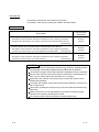
[Startup/Maintenance Instructions]
!
CAUTION
• Before performing the Original Position Return, JOG operation, positioning data or other test in
the test mode, read the manual carefully, fully ensure safety, and set the programmable
controller CPU to STOP.
Not doing so can damage the machine or cause an accident due to misoperation.
A-1
A-1
REVISIONS
* The manual number is given on the bottom left of the back cover.
Print Date
* Manual Number
Revision
Mar., 1999
Jun., 2000
IB (NA)-66900-A
IB (NA)-66900-B
Jun., 2001
IB (NA)-66900-C
Aug., 2001
IB (NA)-66900-D
Nov., 2001
IB (NA)-66900-E
First edition
Correction
Packing List, Section 12.8.2
The product name has been changed to GX Configurator-AP.
Correction
About the Generic Terms and Abbreviations, Packing List
Correction
CONTENTS, About the Generic Terms and Abbreviations, Packing List,
Chapter 1, Section 2.1, Section 2.2, Section 3.1, Chapter 4 to 6,
Section 7.2, Section 8.2, Section 12.4.5, Section 12.11, Appendix 1,
INDEX
Correction
Section 8.2.3, Appendix 2.3, Appendix 2.4
Feb., 2003
New addition
SOFTWARE USER REGISTRATION
Correction
INTRODUCTION, CONTENTS, Section 2.2, Section 4.1, Section 4.2,
Section 4.3, Appendix 2.3, Appendix 2.4, INDEX
IB (NA)-66900-G Correction
SOFTWARE USER REGISTRATION, Section 2.1
IB(NA)- 66900-H Correction
About the Generic Terms and Abbreviations, Section 2.2, Section 4.1,
Section 4.3, Appendix 2.4
Feb., 2004
Jan., 2008
IB (NA)-66900-F
Japanese Manual Version IB-80031-I
This manual confers no industrial property rights or any rights of any other kind, nor does it confer any patent
licenses. Mitsubishi Electric Corporation cannot be held responsible for any problems involving industrial property
rights which may occur as a result of using the contents noted in this manual.
© 1999 MITSUBISHI ELECTRIC CORPORATION
A-2
A-2
—— SOFTWARE USER REGISTRATION ——
After agreeing to the terms of the Software License Agreement included in the package, please access the
MELFANSweb Home Page (http://www.MitsubishiElectric.co.jp/melfansweb) and make a software user
registration. (User registration is free of charge.)
You can also make a registration by faxing or mailing the "Software Registration Card" packed with the
product.
1. Software Registration
You can make a software registration by accessing the MELFANSweb Home Page or faxing or mailing the
"Software Registration Card" packed with the product.
After you have made a software registration, we will register the user and send the "Software registration
confirmation" together with the user ID.
We will also provide the latest information, such as the new product release, version upgrade information
and event information, by direct mail.
2. Notes on Contact
Please ask questions concretely and clearly using terms listed in the manual.
When requesting us to solve a problem, provide us with detailed information for reproducing the problem.
In addition, contact the respective manufacturers when asking questions about the operating system (OS) or
the other vender's software products
User registration is valid only in Japan.
A-3
A-3
INTRODUCTION
Thank you for choosing the Mitsubishi MELSOFT Series Integrated FA software.
Read this manual and make sure understand the functions and performance of MELSOFT series thoroughly
in advance to ensure correct use.
CONTENTS
SAFETY PRECATIONS ................................................................................................................................A- 1
REVISIONS ....................................................................................................................................................A- 2
SOFTWARE USER REGISTRATION...........................................................................................................A- 3
INTRODUCTION............................................................................................................................................A- 4
CONTENTS....................................................................................................................................................A- 4
About Manuals ...............................................................................................................................................A- 8
How to Use This Manual................................................................................................................................A- 9
About the Generic Terms and Abbreviations ................................................................................................A-11
Packing List ....................................................................................................................................................A-11
1. OVERVIEW
1- 1 to 1- 8
1.1 Features ................................................................................................................................................... 1- 2
1.2 Manual Makeup........................................................................................................................................ 1- 7
2. SYSTEM CONFIGURATION
2- 1 to 2- 5
2.1 System Configuration............................................................................................................................... 2- 1
2.2 Operating Environment ............................................................................................................................ 2- 4
3. FUNCTION LIST
3- 1 to 3- 3
3.1 Function List ............................................................................................................................................. 3- 1
4. INSTALLATION AND UNINSTALLATION
4- 1 to 4-12
4.1 Installation ................................................................................................................................................ 4- 1
4.2 Uninstallation............................................................................................................................................ 4- 8
4.3 Starting GX Configurator-AP ................................................................................................................... 4-10
4.4 Ending GX Configurator-AP..................................................................................................................... 4-11
5. SCREEN MAKEUP AND BASIC OPERATIONS
5- 1 to 5- 4
5.1 Screen Makeup ........................................................................................................................................ 5- 1
5.2 Basic Operations...................................................................................................................................... 5- 2
A-4
A-4
6. PROJECT CREATION
6- 1 to 6-11
6.1 Creating a New Project ............................................................................................................................ 6- 2
6.2 Opening the Existing Project ................................................................................................................... 6- 4
6.3 Saving the Project .................................................................................................................................... 6- 5
6.4 Deleting the Project.................................................................................................................................. 6- 6
6.5 Reading the Other Format File (Import file) ............................................................................................ 6- 7
6.5.1 Reading the SW1∗-AD75P format file .............................................................................................. 6- 7
6.5.2 Reading the CSV format file ............................................................................................................. 6- 8
6.6 Write to Other Format File (Export file) ................................................................................................... 6-10
6.6.1 Saving in SW1∗-AD75P format file................................................................................................... 6-10
6.6.2 Saving in CSV format file .................................................................................................................. 6-11
7. SYSTEM CHECKING FROM PERIPHERAL DEVICE
7- 1 to 7-16
7.1 Checking the AD75 Module Version (OS Information)........................................................................... 7- 2
7.2 AD75P Checking Connect....................................................................................................................... 7- 3
7.3 AD75M Servo Starting Up ....................................................................................................................... 7- 6
7.3.1 Servo initial check ............................................................................................................................. 7- 7
7.3.2 Servo model name check ................................................................................................................. 7- 9
7.3.3 Servo upper/lower limit check........................................................................................................... 7-11
7.3.4 Servo speed check............................................................................................................................ 7-14
8. PARAMETER SETTING
8- 1 to 8-12
8.1 Parameters ............................................................................................................................................... 8- 1
8.1.1 Basic parameter 1 setting screen ..................................................................................................... 8- 3
8.1.2 Basic parameter 2 setting screen ..................................................................................................... 8- 4
8.1.3 Extended parameter 1 setting screen .............................................................................................. 8- 5
8.1.4 Extended parameter 2 setting screen .............................................................................................. 8- 6
8.1.5 OPR basic parameter setting screen ............................................................................................... 8- 7
8.1.6 OPR extended parameter setting screen......................................................................................... 8- 8
8.2 Servo Parameters .................................................................................................................................... 8- 9
8.2.1 Servo basic parameter setting screen.............................................................................................. 8-10
8.2.2 Servo adjustment parameter setting screen .................................................................................... 8-11
8.2.3 Servo extension parameter setting screen....................................................................................... 8-12
9. SETTING OF POSITIONING DATA AND START BLOCK DATA
9- 1 to 9-14
9.1 Positioning Data Setting........................................................................................................................... 9- 1
9.2 Positioning Data Checking....................................................................................................................... 9- 4
9.2.1 Error check ........................................................................................................................................ 9- 4
9.2.2 Offline simulation............................................................................................................................... 9- 6
9.3 Start Block Data Setting........................................................................................................................... 9- 8
9.4 Condition Data Setting ............................................................................................................................. 9-10
9.5 Indirect Data Setting................................................................................................................................. 9-12
9.6 M Code Comment Setting ....................................................................................................................... 9-13
A-5
A-5
10. POSITIONING MODULE DATA WRITE/READ/VERIFY
10- 1 to 10- 5
10.1 Write to AD75/Read from AD75/Verify AD75 Data............................................................................. 10- 1
10.2 Flash ROM write/read request to AD75 .............................................................................................. 10- 5
11. POSITIONING DEBUGGING
11- 1 to 11-48
11.1 Monitor.................................................................................................................................................. 11- 2
11.1.1 Monitoring the positioning data/start block data........................................................................... 11- 2
11.1.2 Operation monitor (main screen).................................................................................................. 11- 4
11.1 3 History monitor .............................................................................................................................. 11- 6
11.1.4 Signal monitor ............................................................................................................................... 11- 8
11.1.5 Operation monitor (dialog) ............................................................................................................ 11-11
11.1.6 Servo monitor ................................................................................................................................ 11-17
11.1.7 Sampling monitor .......................................................................................................................... 11-21
11.2 Test....................................................................................................................................................... 11-23
11.2.1 Positioning data-specified operation ............................................................................................ 11-23
11.2.2 Start block data-specified operation ............................................................................................. 11-28
11.2.3 Positioning start test (Current value change test) ........................................................................ 11-31
11.2.4 Speed change test ........................................................................................................................ 11-33
11.2.5 OPR test ........................................................................................................................................ 11-36
11.2.6 JOG operation test ........................................................................................................................ 11-38
11.2.7 MPG operation test ....................................................................................................................... 11-41
11.2.8 Torque control test ........................................................................................................................ 11-43
11.3 Position Control Gain Adjustment ....................................................................................................... 11-45
11.4 Servo Off .............................................................................................................................................. 11-48
12. USEFUL FUNCTIONS
12- 1 to 12-43
12.1 Useful Functions for Project Execution ............................................................................................... 12- 1
12.1.1 Verifying the project data .............................................................................................................. 12- 1
12.1.2 Changing the AD75 model after data setting ............................................................................... 12- 3
12.1.3 Changing the view......................................................................................................................... 12- 4
12.2 Edit Functions for Data Setting............................................................................................................ 12- 5
12.2.1 Cut/copy/paste .............................................................................................................................. 12- 5
12.2.2 Jump .............................................................................................................................................. 12- 9
12.2.3 Clearing the rows/columns ........................................................................................................... 12-10
12.2.4 Initializing the data......................................................................................................................... 12-11
12.3 Copying the Data ................................................................................................................................. 12-12
12.3.1 Copying the data on an axis basis (Axis copy) ............................................................................ 12-12
12.3.2 Copying the data on a start block basis (Start block copy).......................................................... 12-13
12.4 Auxiliary Functions for Data Input........................................................................................................ 12-14
12.4.1 Parameter initializing wizard ......................................................................................................... 12-14
12.4.2 Servo parameter initializing wizard............................................................................................... 12-16
12.4.3 Positioning data input auxiliary function ....................................................................................... 12-18
12.4.4 Start block data input auxiliary function........................................................................................ 12-19
12.4.5 Registering the servo model names............................................................................................. 12-20
A-6
A-6
12.5 GX Configurator-AP Option Function.................................................................................................. 12-23
12.6 Printing the Project Data...................................................................................................................... 12-25
12.6.1 Printer setting ................................................................................................................................ 12-25
12.6.2 Printing........................................................................................................................................... 12-26
12.7 Teaching............................................................................................................................................... 12-30
12.8 Wavy Display........................................................................................................................................ 12-32
12.8.1 Wavy display condition setting...................................................................................................... 12-32
12.8.2 Wavy display execution ................................................................................................................ 12-34
12.9 Tracks Display...................................................................................................................................... 12-36
12.9.1 Tracks display condition setting.................................................................................................... 12-36
12.9.2 Tracks display execution............................................................................................................... 12-38
12.10 Initializing the AD75 ........................................................................................................................... 12-40
12.11 Help .................................................................................................................................................... 12-41
APPENDICES
Appendix- 1 to Appendix - 6
APPENDIX 1 SAMPLING MONITOR AND TRACE SCREEN PRINTING PROCEDURE...........Appendix APPENDIX 2 COMPARISON OF THE AD75 VERSIONS ............................................................Appendix Appendix 2.1 Comparison between AD75P1/2/3 and AD75P1-S3/2-S3/3-S3 ..........................Appendix Appendix 2.2 Comparison between Older and Newer Versions of A1SD75P1-S3/P2-S3/P3-S3 and
AD75P1-S3/P2-S3/P3-S3 .....................................................................................Appendix Appendix 2.3 Comparison between Older and Newer Versions of A1SD75M1/M2/M3 and
AD75M1/M2/M3 ....................................................................................................Appendix Appendix 2.4 Comparison of GX Configurator-AP Versions ......................................................Appendix APPENDIX 3 REFERENCE PROCESSING TIME FOR READ FROM/WRITE TO AD75...........Appendix INDEX
1
3
3
4
5
5
6
Index - 1 to Index - 8
Index ....................................................................................................................................................... Index - 1
Menu-based Index ................................................................................................................................. Index - 6
A-7
A-7
About Manuals
The following manuals are also related to this product.
In necessary, order them by quoting the details in the tables below.
Related Manuals
Manual Number
Manual Name
(Model Code)
Positioning Module Type A1SD75P1-S3/P2-S3/P3-S3, AD75P1-S3/P2-S3/P3 User's Manual
Describes the system configuration, performance specifications, functions, handling, pre-operation
IB-66716
procedure and troubleshooting of Type A1SD75P1-S3/P2-S3/P3-S3 and AD75P1-S3/P2-S3/P3-S3.
(13J871)
(Sold separately)
Positioning Module Type A1SD75M1/M2/M3, AD75M1/M2/M3 User's Manual
IB-66715
Describes the system configuration, performance specifications, functions, handling, pre-operation
procedure and troubleshooting of Type A1SD75M1/M2/M3 and AD75M1/M2/M3.
(13J870)
(Sold separately)
AJ65BT-D75P2-S3 Positioning Module User's Manual
IB-66824
Describes the system configuration, performance specifications, functions, handling, pre-operation
procedure and troubleshooting of Type AJ65BT-D75P2-S3.
(13JL46)
(Sold separately)
CAUTION
Please note that we do not guarantee the Microsoft Windows Operating System
corresponding commercially available software products that we introduce.
The software copyright of this product belongs to Mitsubishi Electric Corporation.
No part of the contents of this manual may be reproduced or transmitted in any
form or by any means without the permission of our company.
Some part of the contents of this manual may not follow the revisions of the
software and hardware.
In principle, the software of this product should be purchased per computer as a
set or under license.
This product (including the manual) may only be used under the software using
agreement.
Please note that we are not responsible for any influence resulting from the
operation of this product (including the manual).
The contents of this manual are subject to change without notice.
R
A-8
R
A-8
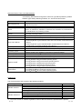
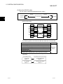
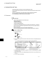
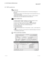
How to Use This Manual
BASIC OPERATION
PURPOSE
Purpose of operation explained in each
chapter, section and paragraph.
Operation to be performed until the actual
operation screen appears.
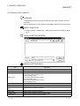
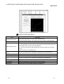
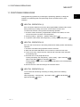
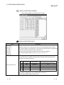
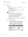
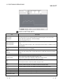
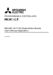
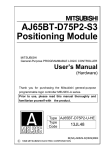
7.1 Checking the AD75 Module Version (OS Information)
PURPOSE
Depending on the software version of the AD75 module, the parameters and
some functions cannot be used.
Before setting various data, check the software version of the module on the
peripheral device.
BASIC OPERATION
1. Click the [Online] → [OS information] menu.
2. Check the software version in the OS information dialog box.
3. To exit, click the "Close" button.
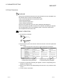
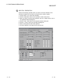
DISPLAY/SETTING SCREEN
DISPLAY/SETTING DATA
Description
Item
Current connected module
Indicates the model of the AD75 connected.
Current OS
Indicates the OS name of the AD75 connected.
Current version
Indicates the software version of the AD75 connected.
The parameters and some functions cannot be used
depending on the software version of the AD75.
Refer to Appendix 2 for differences between the
software versions of the AD75.
DISPLAY/SETTING SCREEN
Screen used to make setting or provide
display for the purpose.
A-9
DISPLAY/SETTING DATA
Explains the display/setting screen items.
A-9
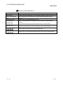
In addition, there are also the following explanations.
HELPFUL OPERATION
Describes application operation if there are multiple purposes and the basic operation and display/setting
data do not provide enough information.
HELPFUL CORRECTIVE ACTIONS
Explains corrective actions if monitored data is abnormal or a test cannot be made.
Provides information relevant to that page, e.g. the items you should be careful of and the functions you
should know.
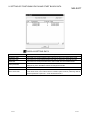
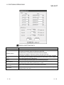
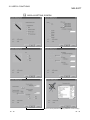
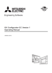
The following table lists the symbols used in this manual and their definitions.
Symbol
[
]
(
)
"
"
<<
A - 10
>>
Description
Represents the name of the menu bar.
→[
] indicates a drop-down menu.
Example: [Project] → [New Project] menu
Represents the tool button on the toolbar corresponding to the drop-down menu.
Example: [Project] → [Save Project] menu (
)
Represents the command button in the dialog box.
Example: "OK" button
Represents the tab in the dialog box.
Example: <<Basic Parameter 1>> tab
A - 10
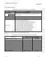
About the Generic Terms and Abbreviations
The following abbreviations and generic names for type AD75 positioning module
software, type AD75 positioning modules, etc. are used in this manual.
Generic Term/Abbreviation
GX Configurator-AP
SW1∗ -AD75P
AD75P
AD75M
AD75
Peripheral device
AD75 User's Manual
Servo amplifier
Servomotor
Positioning system
Personal computer
1-license product
Maltiple-license product
Windows Vista
R
Windows XP
R
Description
Generic product name for type SW0D5C-AD75P-E and SW0D5C-AD75P-EA means a
multiple license product.
Abbreviation for type SW1IVD-AD75P positioning module software package
Generic name for type AD75P1, AD75P2, AD75P3, A1SD75P1, A1SD75P2, A1SD75P3,
AD75P1-S3, AD75P2-S3, AD75P3-S3, A1SD75P1-S3, A1SD75P2-S3, A1SD75P3-S3
and AJ65BT-D75P2-S3 positioning modules
Generic name for type AD75M1, AD75M2, AD75M3, A1SD75M1, A1SD75M2 and
A1SD75M3 positioning modules
Generic name for positioning modules that may be used with GX Configurator-AP.
Generic name for personal computers on which GX Configurator-AP may be used.
Generic name for the following relevant manuals
• Positioning Module Type A1SD75P1-S3/P2-S3/P3-S3, AD75P1-S3/P2-S3/P3 User's
Manual
• Positioning Module Type A1SD75M1/M2/M3, AD75M1/M2/M3 User's Manual
• AJ65BT-D75P2-S3 Positioning Module User's Manual
Generic name for pulse input processing drive units that may be connected to the AD75
Generic name for motors connected to the drive unit (servo amplifier)
Generic name for an equipment set which exercises positioning control, including the
positioning module, servo amplifiers, servomotors and external switches
Abbreviation for IBM PC/AT or compatible DOS/V personal computer
Abbreviation for 1-license product of GX Configurator-AP
Abbreviation for multiple-license product of GX Configurator-AP
Generic term for the following:
Microsoft Windows Vista Home Basic Operating System,
Microsoft Windows Vista Home Premium Operating System,
Microsoft Windows Vista Business Operating System,
Microsoft Windows Vista Ultimate Operating System,
Microsoft Windows Vista Enterprise Operating System
Generic term for the following:
Microsoft Windows XP Professional Operating System,
Microsoft Windows XP Home Edition Operating System
R
R
R
R
R
R
R
R
R
R
R
R
R
R
R
Packing List
The GX Configurator-AP consists of the following products.
Type
SW0D5C-AD75P-E
SW0D5C-AD75P-EA
Product Name
GX Configurator-AP Version 1 (1-license product)
End-user software license agreement
Software registration card
License agreement
GX Configurator-AP Version 1 (Multiple license product)
End-user software license agreement
Software registration card
License agreement
(CD-ROM)
(CD-ROM)
Quantity
1
1
1
1
1
1
n∗1
1
∗1 : The same number of software registration cards as that of licenses are packed with the product.
A - 11
A - 11
MEMO
A - 12
A - 12
1. OVERVIEW
MELSOFT
1. OVERVIEW
This manual describes the functions and operating procedures of
"GX Configurator-AP" (hereinafter referred to as GX Configurator-AP).
GX Configurator-AP is a positioning module software package which can perform the
following functions.
• Setting of positioning data and parameters
• Read/write of data from/to positioning module
• Monitoring of positioning control status
• Test operation of positioning control
• Initial operation test of servo amplifiers and motors
GX Configurator-AP can be used with any of the following positioning modules.
Number of control axis
Positioning
Module Type
1 axis
2 axis
3 axis
1-1
Building block type
Compact building
CC-Link intelligent
block type
device station
AD75P1,
A1SD75P1,
AD75P1-S3,
A1SD75P1-S3,
AD75M1
A1SD75M1
AD75P2,
A1SD75P2,
AD75P2-S3,
A1SD75P2-S3,
AD75M2
A1SD75M2
AD75P3,
A1SD75P3,
AD75P3-S3,
A1SD75P3-S3,
AD75M3
A1SD75M3
-
AJ65BT-D75P2-D3
-
1-1
1
1. OVERVIEW
MELSOFT
1.1 Features
1
This section explains the features of GX Configurator-AP.
(1) Outstanding operability
1) Positioning data and start block data can be cut, copied and
pasted efficiently.
[Useful drag range batch setting operation example]
Drag the batch setting range!
Typing "1" sets "1: ABS Line 1" in the top cell!
Pressing the Enter key batch-sets "1:
ABS Line 1" in all cells in the dragged
range!
2) Data created with Microsoft Excel or Word can be copied and
utilized as positioning data.
R
[Example of utilizing Excel data as positioning data]
Excel worksheet
Copy the address data
created with Excel !
1-2
Positioning setting screen
Choose and paste the
utilized data No. column!
1-2
1. OVERVIEW
MELSOFT
(3) Checking connect of general-purpose servo system
In a general-purpose servo system which uses the AD75P(S3) positioning
module, the checking connect function of GX Configurator-AP allows the
AD75P(S3) to be initialized, I/O signals to/from external devices to be monitored,
and JOG operation to be performed.
The connection of the positioning system can be checked by monitoring signals
from the external devices, and the rotation directions of servomotors can be
checked by performing JOG operation.
Servo amplifiers
AD75P
External devices such as servomotors
and limit switches
Connection of the positioning system using
the AD75P can be checked from the
peripheral device.
(4) Utilization of SW1RX/IVD/NX-AD75P data
Since the data created with type SW1RX/IVD/NX-AD75P positioning module
software package can be utilized on GX Configurator-AP, valuable resources can
be used efficiently.
GX Configurator-AP may also be saved as SW1RX/IVD/NX-AD75P format data.
[Data utilization example]
GX Configurator-AP
SW1IVD-AD75P
Open other format file.
Existing data created
with SW1IVD-AD75P
1-3
1-3
1. OVERVIEW
MELSOFT
(5) Enhanced functions assist debugging and maintenance
Functions have been enhanced the offline simulation function displays a virtual
positioning result which has been calculated from the addresses and command
speeds set in positioning data and the monitor function is useful for debugging
and maintenance of the positioning system, e.g. sampling monitor which shows
the positioning module's I/O signal, external I/O signal and buffer memory states
with a line graph.
[Offline simulation example]
This example assumes that the following
positioning data was offline simulated.
Positioning data #1
Data
No.
Pattern
Control
Method
Address
Command
Speed
1
CONT
ABS
Line 2
200
150,000
pls/s
2
END
ABS
Line 2
100
150,000
pls/s
Positioning data #2
Data
No.
Pattern
Control
Method
Address
Command
Speed
1
-
-
100
-
2
-
-
200
-
2-axis interpolation simulation screen
Locus data is displayed for 2-axis interpolation control.
Waveform data of speed is displayed for 1-axis control.
When positioning data is set, offline simulation allows
you to pre-assume axis operation in advance, reducing
debugging time.
[Sampling monitor example]
Out of AD75's I/O signals, external I/O
signals and status signals, up to 5 points
can be monitored.
In a line graph, up to 3 points can be
monitored from buffer memory.
1-4
1-4
1. OVERVIEW
MELSOFT
(6) Real-time checking of error and warning factors
With the online help function, you can instantaneously check the occurrence
factor and corrective action of the error or warning code displayed on the
operation monitor, error history monitor or other screen of the positioning system.
<Online help function>
<Operation monitor>
Error occurrence!
(7) Simultaneous start of GX Configurator-AP and GX Developer
GX Configurator-AP can be started simultaneously with the GX Developer.
(Two COM ports are required to make communication with the programmable
controller CPU and positioning module at the same time.)
[Example of starting GX Configurator-AP and GX Developer simultaneously]
1-5
1-5
1. OVERVIEW
MELSOFT
(8) Read from AD75/write to AD75/verify AD75 data can be performed
axis-by-axis on a data basis
GX Configurator-AP allows each of the positioning data, start block data and
parameters to be specified as the object of read from AD75/write to AD75/verify
AD75 data axis-by-axis.
Further, positioning data can be specified on a data No. basis, and block No. 0 of
start block data can be specified independently.
Hence, during debugging when data is written frequently for modification,
wasteful waiting time is greatly reduced to improve working efficiency.
[Write range is set to 2-axis positioning data No. 51 to 70]
1-6
1-6
1. OVERVIEW
MELSOFT
1.2 Manual Makeup
This manual is made up of 12 chapters and appendices.
This manual assumes that GX Configurator-AP is used to perform steps from
positioning system connection checking to operation in the following procedure.
<Sequence of steps taken by the user up to positioning system operation>
Step 1: Install and wire the positioning system.
Refer To
• Install and wire the programmable controller (such as the programmable controller CPU,
positioning module and I/O modules), servo amplifiers, motors, external switches and other
AD75 User's Manual
external devices.
Step 2: Check the GX Configurator-AP functions and learn the basic operation.
Refer To
• Check the system with which GX Configurator-AP can be used.
Chapter 2
• Check the functions that can be performed by GX Configurator-AP.
Chapter 3
• Install GX Configurator-AP in the peripheral device and start the program.
Chapter 4
• Learn the GX Configurator-AP screen makeup and basic operation.
Chapter 5
Step 3: Start operation of GX Configurator-AP.
Refer To
• Create a project which will be the object of operation performed on GX Configurator-AP.
Chapter 6
Step 4: Check the connection and initial operation of the positioning system.
Refer To
• Check the version of the positioning module.
• Check connection according to the signal states from the external devices..
• Check the alarm or warning of the positioning module.
• Check the alarm or warning of the servo amplifiers (AD75M only)
• Check that the initial settings are the same on the peripheral device and servo amplifiers.
(AD75M only)
Chapter 7
• Check that the servomotors are run by JOG operation.
• Check that the upper/lower limit, DOG and zero point signals turned on/off by JOG operation.
(AD75M only)
• Check that the servomotor speed does not exceed the maximum speed. (AD75M only)
(To the next page)
1-7
1-7
1. OVERVIEW
MELSOFT
(From the preceding page)
Step 5: Set and write data to the positioning module.
Refer To
• Set the parameters appropriate for the positioning system and control.
• Set the servo parameters appropriate for the specifications of the servo amplifiers and motors
Chapter 8
used.
• Set the positioning data.
• Check the parameter, positioning data and start block data settings on the error check screen.
• Check the positioning data on the offline simulation (virtual positioning) screen.
Chapter 9
• Make the corresponding setting if start block data, condition data, indirect data or M code
comment is required.
• Write the set data to the positioning module.
Step 6: Perform test operation and check and adjust the settings.
Chapter 10
Refer To
• Check positioning control and test on the monitor screen.
• Specify the positioning data and perform test operation.
• Specify the start block data and perform test operation.
• Make software limit test and error compensation by current value change, JOG operation or
manual pulse generator operation.
• Perform original position return test.
Chapter 11
• Perform speed change test to find proper speed.
• If motor torque is not proper, perform torque control test to change the setting.
• Check undershoot, settling time and oscillation width in the test of position control gain 1 of servo
parameters. (AD75M only)
Step 7: Positioning system operation.
• Operate the positioning system with the programmable controller CPU program.
1-8
Refer To
AD75 User's Manual
1-8
2. SYSTEM CONFIGURATION
MELSOFT
2. SYSTEM CONFIGURATION
2.1 System Configuration
(1) Overall configuration of this system
GX Configurator-AP
Peripheral device
(Refer to Section 2.2)
2
Printer
RS-232 cable
RS-232/RS-422
converter
Refer to (2)
RS-422 cable
Conversion cable
(A1SD75-C01HA)
A1SD75P1/P2/P3
A1SD75P1-S3/P2-S3/P3-S3
A1SD75M1/M2/M3
2-1
AJ65BT-D75P2-S3
AD75P1/P2/P3
AD75P1-S3/P2-S3/P3-S3
AD75M1/M2/M3
2-1
2. SYSTEM CONFIGURATION
MELSOFT
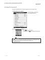
(2) About the RS-232 cable
For use of the FX-232AW(C) (Mitsubishi Electric make)
RS-232
Peripheral
device side
RS-422
FX-232AW(C)
AD75 side
2
RS-232 cable wiring
Peripheral device side
Converter side
Pin No.
Pin No.
FG
1
1
FG
TXD
2
2
TXD
RXD
3
3
RXD
RTS
4
4
RTS
CTS
5
5
CTS
DSR
6
6
DSR
SG
7
7
SG
DTR
20
20
DTR
Shield
The following products of RS-232 and RS-422 cables are recommended.
Cable
Maker
FX-232AW(C) (RS-232/RS-422 converter)
F2-232CAB*1 (when peripheral device has D-sub 25-pin connector)
F2-232CAB-1*1 (when peripheral device has D-sub 9-pin connector)
Mitsubishi
Electric
FX-422CAB (0.3m)
FX-422CAB-150 (1.5m)
AC30N2A (when peripheral device has D-sub 25-pin connector)
*1: To identify compatible products, check the type indicated on the cable's
type label.
2-2
Incompatible product
Compatible product (with F/FX/A)
F2-232CAB
Y990C*****
F2-232CAB(F/FX/A)
Y990C*****
F2-232CAB-1
Y990C*****
F2-232CAB-1(F/FX/A)
Y990C*****
2-2
2. SYSTEM CONFIGURATION
MELSOFT
• Before handling the RS-422 interface conversion cable/converter, please read its
specifications, precautions, etc. carefully in the manual of the corresponding
product and handle it correctly.
• When disconnecting or reconnecting the conversion cable/converter that receives
5VDC power from the RS-422 interface, switch power off on the programmable
controller side before starting work.
• When disconnecting or reconnecting the peripheral device or conversion cable that
does not receive 5VDC power from the RS-422 interface (whose power is
supplied from an external power supply), be sure to use an earth band or touch a
grounded metal object, etc. before starting work to discharge static electricity from
the cable, human body, etc. After that, handle it in the following procedure.
1) Switch power off on the personal computer side.
2) Power off the conversion cable/converter. When it has an FG terminal, ground
it.
3) Connect/disconnect the conversion cable/converter between the personal
computer and programmable controller CPU.
4) Power on the conversion cable/converter.
5) Power on the personal computer.
6) Start up GX Configurator-AP
2-3
2-3
2. SYSTEM CONFIGURATION
MELSOFT
2.2 Operating Environment
The operating environment of GX Configurator-AP is indicated below.
Item
Description
Peripheral device
Personal computer on which Windows
Computer main unit
R
operates.
Refer to the following table "Used operating system and performance required for
CPU
Required memory
Hard disk free space
personal computer".
10MB or more 1
Disk drive
CD-ROM disk drive
Display
800 × 600 dot or more resolution 2
Microsoft
R
Windows
R
95 Operating System
Microsoft
R
Windows
R
98 Operating System
Microsoft
R
Windows
R
Millennium Edition Operating System
Microsoft
Operating system
R
Microsoft
R
Microsoft
Windows NT
R
Workstation Operating System Version 4.0
Windows
R
2000 Professional Operating System
R
Windows
R
XP Professional Operating System
Microsoft
R
Windows
R
XP Home Edition Operating System
Microsoft
R
Windows Vista
R
Home Basic Operating System
Microsoft
R
Windows Vista
R
Home Premium Operating System
Microsoft
R
Windows Vista
R
Business Operating System
Microsoft
R
Windows Vista
R
Ultimate Operating System
Microsoft
R
Windows Vista
R
Enterprise Operating System
1: At minimum, free space of 15GB is required for Windows Vista .
R
2: Resolution 1024 × 768 pixels or higher is recommended for Windows Vista .
R
Used operating system and performance required for personal computer
Operating system
Windows
R
95 (Service Pack 1 or more)
Windows
R
Windows
R
Performance Required for Personal Computer
CPU
Required memory
Pentium
R
133MHz or more
32MB or more
98
Pentium
R
133MHz or more
32MB or more
Me
Pentium
R
150MHz or more
32MB or more
Pentium
R
133MHz or more
32MB or more
133MHz or more
64MB or more
300MHz or more
128MB or more
Windows NT
R
Workstation 4.0 (Service Pack 3 or more)
Windows
R
2000 Professional
Pentium
R
Windows
R
XP Professional
Pentium
R
Windows
R
XP Home Edition
Pentium
R
300MHz or more
128MB or more
Windows Vista
R
Home Basic
Pentium
R
1GHz or more
1GB or more
Windows Vista
R
Home Premium
Pentium
R
1GHz or more
1GB or more
Windows Vista
R
Business
Pentium
R
1GHz or more
1GB or more
Windows Vista
R
Ultimate
Pentium
R
1GHz or more
1GB or more
Windows Vista
R
Enterprise
Pentium
R
1GHz or more
1GB or more
2-4
2-4
2. SYSTEM CONFIGURATION
MELSOFT
The functions shown below are not available for Windows XP and Windows
Vista .
If any of the following functions is attempted, this product may not operate normally.
R
R
Start of application in Windows compatible mode
Fast user switching
Remote desktop
Large fonts (Details setting of Display Properties)
R
Also, 64-bit version Windows XP and Windows Vista are not supported.
Use a USER authorization or higher in Windows Vista .
R
R
R
2-5
2-5
3. FUNCTION LIST
MELSOFT
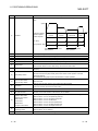
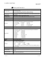
3. FUNCTION LIST
3.1 Function List
(1) Function list
GX Configurator-AP functions are listed below mode-by-mode.
Mode
Main Screen
Function
Description
Set the basic parameters1, basic parameters2, extended
Parameter
Parameter setting
parameters1, extended parameters2, OPR basic parameters and
OPR extended parameters on an axis basis.
3
Servo parameter
Servo parameter
Set the servo basic parameters, servo adjustment parameters and
(AD75M only)
setting
servo extension parameters on an axis basis.
Positioning data
Set the positioning data, such as pattern, control method,
setting
accel/decel time and address, on an axis basis.
Positioning data
Positioning data
axis #1
Positioning data
axis #2
Positioning data
axis #3
Edit
monitor
Positioning data test
Teaching
M code comment
setting
Offline simulation
Perform test operation of positioning control on an axis or
positioning data basis.
Set the feed address of the moved axis to the address of
positioning data by JOG operation or the like.
Set comments to the M codes assigned to the positioning data on
an axis basis.
Assume axis operation from the set positioning data on an axis
basis.
Start block data
Set the starting mode, etc. of the positioning data specified for
setting
points on an axis basis.
Start block axis
Start block data
Monitor the point at which positioning control is being executed on
#1
monitor
an axis basis.
Start block axis
#2
Start block data test
Perform test operation of positioning control from the point of the
specified block on an axis basis.
Start block axis
Condition data
Set the data which is used as the starting condition of the start
#3
setting
block data on an axis basis.
Indirect data setting
Operation
monitor (test)
Set the positioning data numbers set to the indirect designating
buffer memory of the AD75 on an axis basis.
Operation monitor
Monitor the operating states, such as addresses, axis speeds, axis
(main screen)
statuses and executed positioning data numbers, of all axes.
History monitor
Monitor
Monitor the positioning data during execution on an axis basis.
Signal monitor
Monitor the error, warning, start or error-time start history of all
axes.
Monitor the X/Y devices, external signals or status signals of all
axes.
Operation monitor
Monitor the control states, AD75 parameter settings or others of all
(dialog)
axes.
Servo monitor
Monitor the servo amplifier and servomotor states of all axes.
Test the positioning data number-specified start, current value
Operation test
change, speed change, original position return, JOG operation and
manual pulse generator operation of all axes.
3-1
3-1
3. FUNCTION LIST
Mode
Monitor
Main Screen
Sampling
monitor
AD75P checking
connect
(AD75P only)
Diagnosis
MELSOFT
Function
Description
Sampling monitor
Monitor the specified signals and buffer memory data while
simultaneously sampling them.
AD75P checking
Display signals from external devices. Also test initial operation by
connect
JOG operation.
Initial check
Monitor the error/warning history of the AD75M or servo amplifiers.
Module name
Compare the servo parameters read from the servo amplifiers to
AD75M servo
check
the AD75M with the servo parameters on the peripheral device.
starting up
Upper/lower limit
Judge the upper and lower limit switch operations by JOG
(AD75M only)
check
operation.
RPM check
AD75M position
control gain
(AD75M only)
3
Display the motor speeds for JOG operation and the motor speeds
set to the servo basic parameters.
AD75M position
Adjust the servomotor characteristics such as response level and
control gain
settling time.
Trace the specified data (position instruction, servomotor speed,
Wavy display
Wavy display
etc.) for a given time and display the waveform data relative to the
time axis.
Trace*1
Tracks displays
Tracks displays
Trace the position command or real value for a given time and
display the track data of the axes.
*1 The following positioning modules do not have the trace mode.
• AD75P1/P2/P3
• A1SD75P1/P2/P3
3-2
3-2
3. FUNCTION LIST
MELSOFT
(2) Menu list
The menu bar drop-down menus are listed below.
Project
New Project
Open Project
Save Project
Save as Project
Delete Product
Verify Project
Import file
Online
File reading of SW1RX/IVD/NX-AD75P
File reading of CSV form positioning data
File reading of trace data
Export file
Signal monitor
Operation monitor
Servo monitor
Test
Test start
Start condition
Operation Test
Teaching
All axis On/Off
Designate Off
Designate #1 Off
Designate #2 Off
Designate #3 Off
Error Reset
Error Reset #1
Error Reset #2
Error Reset #3
M code Off
M code #1 Off
M code #2 Off
M code #3 Off
File writing of SW1RX/IVD/NX-AD75P
File writing of CSV form positioning data
File writing of trace data
Change AD75 model
Print
Printer setup
Latest file
Exit
Edit
View
Cut
Copy
Paste
Select all
Jump
Clear row
Clear column
Axis copy
Start block copy
Positioning data input
Start block data input
Parameter data input
Servo parameter
M code comment
Condition data edit
Indirect data edit
Offline simulator
Toolbar
Project toolbar
Edit toolbar
Online toolbar
Status bar
Change menu
Move upward
Select Axis
Read from AD75
Write to AD75
Verify AD75 data
OS information
Flash-ROM request
Initialize AD75
Monitor
Monitor start
History monitor
Tool
Initialize data
Initialize parameter
Initialize servo parameter
Register servo name
Error check
Option
Help
Error/Warning Help
List of Buffer memory
About
Connection to MELFANSweb
Axis #1
Axis #2
Axis #3
Select start block
Edit property dialog
Large Icons
Small Icons
List view
Detailed view
3-3
3-3
4. INSTALLATION AND UNINSTALLATION
MELSOFT
4. INSTALLATION AND UNINSTALLATION
This chapter describes how to install and uninstallation of GX Configurator-AP.
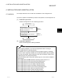
4.1 Installation
This section explains the installation procedure and operation of GX Configurator-AP.
(1) Installation procedure
Install GX Configurator-AP in the following procedure.
New installation
Install the product.
Register the Name and Company.
Register the product ID.
Refer to
Section 4.1.
Boot the application.
Check whether the product has been
installed properly.
Refer to
Section 4.3.
4
Complete
(2) Installation operation
Check the following before starting installation.
• Before starting installation, close all other applications that are running on
Microsoft Windows Operating System.
• The installer may not work normally because the update program of operating
system or other companies' software such as Windows Update and java update
may start automatically. Please install the driver after changing the setting of the
update program not to start automatically.
• When the following OS is being used, please logon as a user with the attribute of
Administrator.
Microsoft Windows NT Workstation Operating System Version 4.0
Microsoft Windows 2000 Professional Operating System
Microsoft Windows XP Professional Operating System
Microsoft Windows XP Home Edition Operating System
Microsoft Windows Vista Home Basic Operating System
Microsoft Windows Vista Home Premium Operating System
Microsoft Windows Vista Business Operating System
Microsoft Windows Vista Ultimate Operating System
Microsoft Windows Vista Enterprise Operating System
R
R
R
4-1
R
R
R
R
R
R
R
R
R
R
R
R
R
R
R
R
R
4-1
4. INSTALLATION AND UNINSTALLATION
MELSOFT
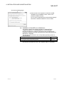
(a) Installing the product
The screens used for explanation in this section are those of Microsoft
Windows 98 Operating System.
R
R
®
Double-click here.
1) Boot Windows Explorer and click the drive where the
disk is inserted.
Double-click "Setup.exe".
®
To display Windows Explorer, choose [Start] [Programs] - [Windows Explorer].
: When user account control is enabled in Windows
Vista , the following screen appears.
Click "Allow".
R
4
2) If either of the left screens appears, perform operation in
accordance with the instructions given in (b).
After the operation is over, restart installation operation.
If the left screen appears, perform operation in accordance
with the instructions given in (c).
After the operation is over, restart installation operation.
If the left screen appears, perform operation in accordance
with the instructions given in (d).
After the operation is over, restart installation operation.
(To the next page)
4-2
4-2
4. INSTALLATION AND UNINSTALLATION
MELSOFT
(From the preceding page)
3) Type the name and company, and click Next> .
As the confirmation dialog box appears, follow the
message and perform operation.
4) Enter the product ID and click Next> .
The product ID is given in the "Software Registration
Card" packed with the product.
5) Specify the installation destination folder.
Click Next> if the destination folder displayed is OK.
To change the folder, click Browse and specify a new
drive and folder.
: The following screen appears in Windows Vista .
Click "Install this driver software anyway".
This screen may appear in several times.
R
(To the next page)
4-3
4-3
4. INSTALLATION AND UNINSTALLATION
MELSOFT
(From the preceding page)
The either of the following screens may appear behind
the Windows Security screen. Then, press the "Alt" +
"Tab" keys to bring it to the front.
Click "OK" on the following screens.
: For Windows XP, the following screen appears at
first installation.
Click "Continue".
We checked operations in Windows XP (Problems
never occur after installation.)
The following screen may appear behind another
screen. Then, press the "Alt" + "Tab" keys to bring it
to the front.
R
R
6) This completes installation.
Click OK .
(To the next page)
4-4
4-4
4. INSTALLATION AND UNINSTALLATION
MELSOFT
(From the preceding page)
7) When the left screen appears on Windows Vista ,
regardless of the installation result, choose "This
program installed correctly".
Do not choose "Reinstall using recommended settings",
because the installer installs an ncorrect module.
R
(b) Installation of dcom95.exe or Axdist.exe
This section explains the updating operation of Windows using
"Update\dcom95.exe" or "Update\Axdist.exe" on the CD-ROM.
Execute dcom95.exe or Axdist.exe provided for GX Configurator-AP.
Install GX Configurator-AP after executing the exe file and restarting the
IBM-PC/AT compatible.
The exe file to be executed on the corresponding operating system is
indicated below.
R
OS
Microsoft Windows 95 Operating System
Microsoft Windows 98 Operating System
Microsoft Windows NT Workstation Operating System Version 4.0
R
R
R
R
R
R
File name
dcom95.exe
Axdist.exe
Axdist.exe
(dcom95.exe and Axdist.exe are in the "Update" folder on CD-ROM.)
4-5
4-5
4. INSTALLATION AND UNINSTALLATION
(c) Installation of 50comupd.exe
MELSOFT
®
This section explains the updating operation of Windows using
"Update\50comupd.exe" on the CD-ROM.
1) Click the Yes button to start updating Windows.
2) Accept the agreement on the left screen and click
the Yes button.
3) Click Yes to restart.
After a restart, perform the installation operation in (a).
4-6
4-6
4. INSTALLATION AND UNINSTALLATION
MELSOFT
(d) Installation of EnvMEL
When user account control is enabled in Windows Vista , the following
screen appears. Click "Allow".
R
: After executing the above exe file, install the product again. If this
product is not installed properly at this time, reboot the personal
computer.
When the following screen appears on Windows Vista , regardless of the
installation result, choose "This program installed correctly".
Do not choose "Reinstall using recommended settings", because the
installer installs an incorrect module.
R
(e) Registered icon
The following icon is registered by installing GX Configurator-AP.
REMARK
®
®
When Windows XP or Windows Vista is used, the icons are registered to [Start] [All Programs] - [MELSOFT Application].
4-7
4-7
4. INSTALLATION AND UNINSTALLATION
MELSOFT
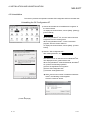
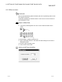
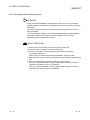
4.2 Uninstallation
This section provides the operation to delete GX Configurator-AP from the hard disk.
Uninstalling the GX Configurator-AP
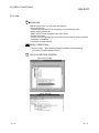
1) Choose and double-click "Add/Remove Programs" in
the Control Panel.
To display the Control Panel, choose [Start] - [Setting] [Control Panel].
REMARKS
When using Windows XP, choose "Add or Remove
Programs" from the Control Panel.
When using Windows Vista , Chose "Uninstall a
program" from the Control Panel in.
To display the Control Panel, choose [Start] - [Control
Panel].
R
R
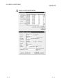
2) Choose " GX Configurator-AP ".
After making selection, click Add/Remove .
REMARKS
The screen shown on the left is that of Windows 98.
The displayed screen varies with the OS.
When using Windows 2000 Professional, Windows
XP, perform the following operation.
(a) Click "Change/Remove Programs".
(b) Click "GX Configurator-AP".
(c) Click the "Change/Remove".
R
R
R
: When user account control is enabled in Windows
Vista , the following screen appears.
Click the "Continue" button.
R
(To the next page)
4-8
4-8
4. INSTALLATION AND UNINSTALLATION
MELSOFT
(From the preceding page)
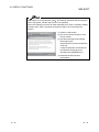
3) Confirm that GX Configurator-AP may be removed.
When uninstalling the program, click the "Yes" button to
start uninstallation.
When not executing uninstallation, click the "No".button
to return to the previous screen.
*Components indicate the installed icon files.
4) If the left screen has appeared, click the "No To All"
button.
If you click the "Yes" or "Yes To All" button, the shared
file of the Windows compatible MELSOFT software is
removed. Therefore, click the "No To All" button when
removing GX Configurator-AP only.
R
5) Click the "OK" button if the "Uninstall successfully
completed" message appears.
If a warning appears for the files that were not
removed, open "Explorer", click the files, and remove
unnecessary files.
Note that if you remove necessary files accidentally,
the other applications may not be booted.
4-9
4-9
4. INSTALLATION AND UNINSTALLATION
MELSOFT
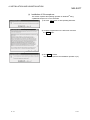
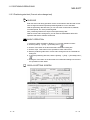
4.3 Starting GX Configurator-AP
This section provides how to start GX Configurator-AP in the start menu.
R
1) Click the Windows "Start" button and move the
cursor to [Programs ] → [MELSOFT application].
: [All Programs] appears when using Windows
XP.
↓
2) Click [GX Configurator-AP].
↓
3) GX Configurator-AP starts.
4 - 10
4 - 10
R
4. INSTALLATION AND UNINSTALLATION
MELSOFT
4.4 Ending GX Configurator-AP
This section describes how to end GX Configurator-AP in the project menu.
(1) Menu-driven exit method
Click the [Project] [Exit] menu.
GX Configurator-AP ends.
(2) Title bar-driven exit method
and choose [Close].
Click
at the right end of the title bar.
Alternatively, click
GX Configurator-AP cannot be exited while online status such as test mode, trace
mode, Write to AD75/Read from AD75/Verify AD75 Data is set.
Exit it with offline status.
4 - 11
4 - 11
4. INSTALLATION AND UNINSTALLATION
MELSOFT
MEMO
4 - 12
4 - 12
5. SCREEN MAKEUP AND BASIC OPERATIONS
MELSOFT
5. SCREEN MAKEUP AND BASIC OPERATIONS
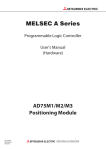
5.1 Screen Makeup
This section provides the screen makeup and various tools of GX Configurator-AP.
Screen minimize
button
Title bar
Menu bar
Project toolbar
Drop-down menu
Online toolbar
Screen magnify/
reduce button
Screen close
button
Edit toolbar
5
Menu screen
5-1
Status bar
Main screen
5-1
5. SCREEN MAKEUP AND BASIC OPERATIONS
MELSOFT
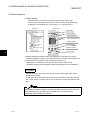
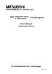
5.2 Basic Operations
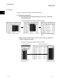
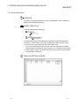
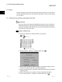
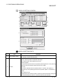
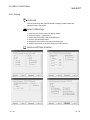
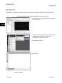
(1) Menu screen
The menu screen is used to choose the mode and main screen type.
There are tree and image menu screens, either of which can be selected by
clicking the corresponding tab, <<Tree menu>> or <<Image menu>>.
Tree menu
Image menu
Edit mode*2
*1
*1
Monitor mode*2
Positioning data edit
Choose axis number with
any of connectors 1 to 3.
*1
Operation monitor
Parameter edit
*1
*1
Diagnosis mode*2
Trace mode*2
5
*1 Double-clicking the module model name (AD75P-S3 <Axis #3> in the above
example) displays the menu of the mode selected on the main screen with an icon.
*2 Clicking the icon provides the same operation results as in *1.
Displaying the command box lists the menu items of the chosen mode.
The above diagram shows a display example provided when you click [Monitor].
Remarks
Use the "F6" key to move the cursor from the main screen to the menu screen
through the keyboard.
To move the cursor from the menu screen to the main screen, move the cursor to
the <<Tree menu>>/<<Image menu>> tab on the menu screen and press the "F6"
key.
Operations described in Chapter 6 and later are those selected from the tree menu.
When performing any operation from the image menu, confirm the above
explanation before starting the operation.
5-2
5-2
5. SCREEN MAKEUP AND BASIC OPERATIONS
MELSOFT
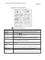
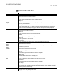
(2) Basic operation for dialog boxes
1) Tab
1) Tab
2) List box
3) Radio
button
5) Check box
7) Spin box
4) Text box
6) Command button
1) Tab
Click the setting item name to select.
2) List box
Click
to list choices, then click the item to be chosen.
3) Radio button
Click ! to choose one from among more than one selection item.
4) Text box
Type characters.
5) Check box
To execute any item, click " to check it off.
6) Command button
Click this button when executing "OK", "Cancel" or the like, or when
displaying the dialog box.
7) Spin box
Used either to type a value directly or to change a value by clicking
.
When typing a value directly, click inside the spin box and enter the
value from the keyboard.
When clicking
to change a value, click
click
to decrease.
to increase the value, or
Remarks
When performing operation from the keyboard, choose the setting item with the
"Tab" key.
When there are two or more choices, use the "←", "→", "↑" and/or "↓" key.
5-3
5-3
5. SCREEN MAKEUP AND BASIC OPERATIONS
MELSOFT
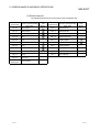
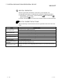
(3) Shortcut key list
The following shortcut keys can be used on GX Configurator-AP.
Shortcut Key
Function (Corresponding
Tool
Menu Item)
Button
Shortcut Key
Function (Corresponding
Tool
Menu Item)
Button
Ctrl + N
New Project
Ctrl + 1
Select Axis #1
-
Ctrl + O
Open Project
Ctrl + 2
Select Axis #2
-
Ctrl + S
Save Project
Ctrl + 3
Select Axis #3
-
Ctrl + P
Print
Ctrl + B
Select start block
-
Alt + F4
Exit
Ctrl + T
Write to AD75
Ctrl + X
Cut
Ctrl + M
Monitor start
Ctrl + C
Copy
Alt + 1
History Monitor
-
Ctrl + V
Paste
Alt + 2
Signal Monitor
-
Ctrl + A
Select all
-
Alt + 3
Operation Monitor
-
Ctrl + J
Jump
-
Alt + 4
Servo Monitor
-
Ctrl + Y
Clear row
-
Move upward
-
Ctrl +
Backspace
5-4
-
5-4
6. PROJECT CREATION
MELSOFT
6. PROJECT CREATION
A project is a collection of parameters, servo parameters (AD75M only), positioning
data and start block data.
<GX Configurator-AP project makeup>
Parameters (Axis #1 to #3)
There are basic parameters 1, basic parameters 2, extended parameters 1,
extended parameters 2, OPR basic parameters and OPR extended parameters.
Project
Servo parameters (Axis #1 to #3: AD75M only)
Data transmitted from the AD75M to the servo amplifiers.
There are servo basic parameters, servo adjustment parameters and servo
expansion parameters.
Positioning data (Axis #1 to #3)
Data used to set the control data such as positioning control method and
addresses.
Data No. 1 to 600 can be set to each axis.
Start block data (Axis #1 to #3)
Data used to attach a condition to a positioning control start and set the repeat count.
6
When executing "New Project" or "Save as Project", you cannot use the following
characters and symbols in the project path and project name to be specified.
/ , : ; * " < > | \\ COM LPT AUX CON PRN NUL CLOCK$
6-1
6-1
6. PROJECT CREATION
MELSOFT
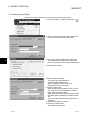
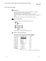
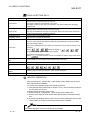
6.1 Creating a New Project
Set the AD75 model used to create a new project and the project items.
1) Click the [Project] → [New Project] menu (
).
↓
2) Click the AD75 connected module "Reference"
button in the New project file dialog box.
↓
3) Choose the AD75 model name in the list box.
The AD75 Model and AD75 Axis select radio
buttons may also be used to make that selection.
6
4) Click the "OK" button.
↓
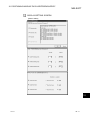
5) Set the project save path.
The project save path defaults to
C:\MELSEC\AD75WINE\USR.
When changing it, refer to "HELPFUL
OPERATION" on the next page.
6) Set the project name.
When specifying the project file name, you can
use a total of up to 150 characters to set the
project path and project name.
When setting the project path and project name,
the total number of characters should be within
150.
This screen assumes that the project name is
"SAMPLE".
7) Set the project title as required.
8) Click the "Create" button.
This creates a new project.
6-2
6-2
6. PROJECT CREATION
MELSOFT
Project saving destination and file name
If the project save path and project name described on the preceding page are
used to save the positioning data, the data is saved with the following file name
and extension.
C:\MELSEC\AD75WINE\USR\SAMPLE\SAMPLE.W75
Project save path
Project name File name Extension*
* The extension is fixed (W75).
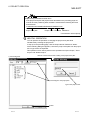
HELPFUL OPERATION
You can perform the operation of changing the project save path while
simultaneously checking the project tree.
In step 5) on the preceding page, click the Project file set "Reference" button.
As the following dialog box appears, choose the project save path from the project
tree or type it from the keyboard.
This operation is also used to perform such operations as "Open Project", "Save
Project" and "Delete Project".
1) Choose the drive.
Click the "Create" button when creating a new project save path.
2) Choose/type a new project path.
Type a new project name.
3) Click.
6-3
6-3
6. PROJECT CREATION
MELSOFT
6.2 Opening the Existing Project
This section explains the operation of opening the saved project.
1) Click the [Project] → [Open Project] menu (
↓
2) Click the name of the project you will open.
For the setting operation of referring to the save
path of the project to be opened, refer to
"HELPFUL OPERATION" in Section 6.1.
3) Click the "Open" button.
↓
4) The specified project opens.
6-4
6-4
).
6. PROJECT CREATION
MELSOFT
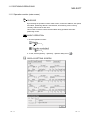
6.3 Saving the Project
PURPOSE
The project file which is currently edited is saved.
BASIC OPERATION
• Save
Click the [Project] → [Save Project] menu (
).
• Save as
Click the [Project] → [Save as Project] menu.
When specifying the project file name, you can use a total of up to 150
characters to set the project path and project name.
When setting the project path and project name, the total number of characters
should be within 150.
For the operation of setting the project save path and project name, refer to
"HELPFUL OPERATION" in Section 6.1.
DISPLAY/SETTING SCREEN
6-5
6-5
6. PROJECT CREATION
MELSOFT
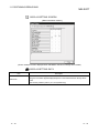
6.4 Deleting the Project
PURPOSE
The project is deleted from HD, FD or the like.
BASIC OPERATION
1. Click the [Project] → [Delete Project] menu.
2. In the Delete project file dialog box, choose the project you want to delete and
click the "Delete" button.
Refer to Section 6.2 for the operation of changing the project path.
3. As the project file deletion confirmation dialog box appears, click the "Yes"
button.
4. The project is deleted.
DISPLAY/SETTING SCREEN
6-6
6-6
6. PROJECT CREATION
MELSOFT
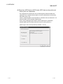
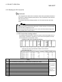
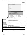
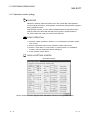
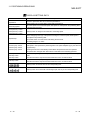
6.5 Reading the Other Format File (Import file)
6.5.1 Reading the SW1∗-AD75P format file
PURPOSE
The positioning data, M code comments, start block data, condition data, indirect
data, parameters and servo parameters are read from the file saved on MS-DOS
version SW1∗-AD75P to the project of GX Gonfigurator-AP.
BASIC OPERATION
1. Click the [Project] → [Import file] → [File reading of SW1RX/IVD/NX-AD75P]
menu.
DISPLAY/SETTING SCREEN
DISPLAY/SETTING DATA
Item
Description
File, folder indication
Show the folders existing in the specified drive or folder and the corresponding type of files.
File name
Set the file name you will read.
Files of type
Select SW1RX/IVD/NX-AD75P File (*.D75).
Look in
Choose the drive or folder where the file you will read exists.
"Up one level folder" button Click this button to show the folder one level above the currently displayed folder.
"List" button
Click this button to list files and folders.
"Details" button
Click this button to display the file and folder in detail.
"Open" button
Click this button to read the file.
6-7
6-7
6. PROJECT CREATION
MELSOFT
6.5.2 Reading the CSV format file
PURPOSE
GX Configurator-AP allows CSV format files created with spreadsheet software or
the like to be read as positioning data (axis #1 to #3). (Parameters and start block
data cannot be read.)
The creating method and reading operation of CSV format data are described
below.
• If all items that make up positioning data have not been entered, CSV format data
cannot be read, resulting in an error.
• Since CSV format data is read axis-by-axis, create CSV format data noting which
axis (#1/#2/#3) data is being created.
(1) CSV format data creating method
The following sheet indicates the items and values of CSV format data set on a
column basis. It should be noted that you cannot set the interpolation axis and
circular addresses for interpolation control.
<Example of data set to spreadsheet software>
1)
2)
3)
4)
5)
6)
7)
8)
9)
10)
<Data set to the above spreadsheet software was read with
GX Configurator-AP >
Num
ber
Setting
1)
Line 1 from table top is positioning No. 1 data and line 2 is positioning No. 2 data.
2)
Set the positioning control pattern in column 1 from left. Set any value of 0 to 2.
3)
Set the control method in column 2 from left. Set it with 1 to 9 and A to I.
4)
Set the accel time in column 3 from left. Set it with 0 to 3.
5)
Set the decel time in column 4 from left. Set it with 0 to 3.
6)
Set the address in column 5 from left.
7)
Set the circular address in column 6 from left.
8)
Set the command speed in column 7 from left.
9)
Set the dwell time in column 8 from left.
10)
Remarks
Refer to Section
9.1 for details of
data
corresponding to
values and
alphabets to be
set.
Set the M code in column 9 from left.
6-8
6-8
6. PROJECT CREATION
MELSOFT
(2) CSV format file reading operation
BASIC OPERATION
1. Click the [Project] → [Import file] → [File reading of CSV form positioning data]
menu.
DISPLAY/SETTING SCREEN
DISPLAY/SETTING DATA
Item
Description
File, folder indication
Show the folders existing in the specified drive or folder and the corresponding type of files.
File name
Set the file name to be read to the project.
Choose the read positioning data of any of the axes.
• To read the positioning data of axis #1
CSV File(1Axis)(*.CSV)
Files of type
• To read the positioning data of axis #2
CSV File(2Axis)(*.CSV)
• To read the positioning data of axis #3
CSV File(3Axis)(*.CSV)
Look in
Choose the drive or folder where the file you will read exists.
"Up one level folder" button Click this button to show the folder one level above the currently displayed folder.
"List" button
Click this button to list files and folders.
"Details" button
Click this button to display the file and folder in detail.
"Open" button
Click this button to read the file.
6-9
6-9
6. PROJECT CREATION
MELSOFT
6.6 Write to Other Format File (Export file)
6.6.1 Saving in SW1∗-AD75P format file
PURPOSE
The positioning data, M code comments, start block data, condition data, indirect
data, parameters and servo parameters set on GX Configurator-AP are saved in
the MS-DOS version SW1∗ -AD75P format file.
BASIC OPERATION
1. Click the [Project] → [Export file] → [File writing of SW1RX/IVD/NX-AD75P]
menu.
DISPLAY/SETTING SCREEN
DISPLAY/SETTING DATA
Item
File, folder indication
Description
Show the folders existing in the specified drive or folder and the corresponding type of files.
File name
Set the file name to be saved in the other format file.
Save as type
Select SW1RX/IVD/NX-AD75P File (*.D75).
Save in
Choose the drive or folder where the file will be saved.
"Up one level folder" button Click this button to show the folder one level above the currently displayed folder.
"Create New Folder"
button
Click this button to create a "new folder".
"List" button
Click this button to list files and folders.
"Details" button
Click this button to display the file and folder in detail.
"Save" button
Click this button to save the other format file.
6 - 10
6 - 10
6. PROJECT CREATION
MELSOFT
6.6.2 Saving in CSV format file
PURPOSE
The positioning data set in the GX Configurator-AP project is saved in the CSV
format file.
Refer to Section 6.5.2 for the positioning data setting items and CSV format data.
BASIC OPERATION
1. Click the [Project] → [Export file] → [File writing of CSV form positioning data]
menu.
DISPLAY/SETTING SCREEN
DISPLAY/SETTING DATA
Item
Description
File, folder indication
Show the folders existing in the specified drive or folder and the corresponding type of files.
File name
Set the file name to be read to the project.
Choose the saved positioning data of any of the axes.
• To save the positioning data of axis #1
CSV File(1Axis)(*.CSV)
• To save the positioning data of axis #2
CSV File(2Axis)(*.CSV)
• To save the positioning data of axis #3
CSV File(3Axis)(*.CSV)
Save as type
Save in
Choose the drive or folder where you will save the data.
"Up one level folder" button Click this button to show the folder one level above the currently displayed folder.
"Create New Folder"
button
Click this button to create a "new folder".
"List" button
Click this button to list files and folders.
"Details" button
Click this button to display the file and folder in detail.
"Save" button
Click this button to save the other format file.
6 - 11
6 - 11
7. SYSTEM CHECKING FROM PERIPHERAL DEVICE
MELSOFT
7. SYSTEM CHECKING FROM PERIPHERAL DEVICE
On the peripheral device, check the connection of the AD75 and external devices
(servo amplifiers, servomotors, etc.) and perform the initial operation test of
servomotors.
For the AD75M, operation tests can be made on the peripheral device to check the
servo amplifier status and servo parameters and further to check that the servo
parameters are valid.
• When the model used is the AD75P1/P2/P3, A1SD75P1/P2/P3, AD75P1-S3/P2S3/P3-S3 or A1SD75P1-S3/P2-S3/P3/S3, perform the following operation.
Section 7.1 Checking the AD75 Module Version (OS Information)
Section 7.2 AD75P Checking Connect
• When the model used is the AJ65BT-D75P2-S3, perform the following operation.
Section 7.2 AD75P Checking Connect
• When the model used is the AD75M1/M2/M3 or A1SD75M1/M2/M3, perform the
following operation.
Section 7.1 Checking the AD75 Module Version (OS Information)
Section 7.3 AD75M Servo Starting Up
Section 7.3.1 Servo initial check
Section 7.3.2 Servo model name check
Section 7.3.3 Servo upper/lower limit check
Section 7.3.4 Servo speed check
7
Before starting the OS information checking, AD75P checking connect or AD75M
servo starting up, make COM setting using the optional function (refer to Section
12.5).
If the COM setting is incorrect, a communication error will occur.
To check the usable COM port, perform the following operation.
1) Click the Microsoft Windows Operating System "Start" button and choose
[Setting] → [Control Panel].
2) As the control panel opens, choose "System".
3) As the system property dialog box opens, choose the <<Device Manager>> tab.
4) Choose "Ports (COM & LPT)" and check the usable COM port.
R
7-1
R
7-1
7. SYSTEM CHECKING FROM PERIPHERAL DEVICE
MELSOFT
7.1 Checking the AD75 Module Version (OS Information)
PURPOSE
Depending on the software version of the AD75 module, the parameters and some
functions cannot be used.
Before setting various data, check the software version of the module on the
peripheral device.
BASIC OPERATION
1. Click the [Online] → [OS information] menu.
2. Check the software version in the OS information dialog box.
3. To exit, click the "Close" button.
DISPLAY/SETTING SCREEN
7
DISPLAY/SETTING DATA
Item
Current connected module
Current OS
Description
Indicates the model of the AD75 connected.
Indicates the OS name of the AD75 connected.
Indicates the software version of the AD75 connected.
Current version
The parameters and some functions cannot be used depending on the software version of
the AD75.
Refer to Appendix 2 for differences between the software versions of the AD75.
7-2
7-2
7. SYSTEM CHECKING FROM PERIPHERAL DEVICE
MELSOFT
7.2 AD75P Checking Connect
PURPOSE
Make sure that the cables between AD75P and servo amplifiers and between
servomotors, servo amplifiers and external devices are connected properly.
BASIC OPERATION
1. Power on the positioning system and STOP the programmable controller CPU.
2. Choose AD75P Checking connect.
Double-click.
Double-click.
3. The online processing (test mode shift ) confirmation dialog box appears.
Click the "Initialize" button to check connection after initializing the AD75P.
Click "OK" to check connection without initializing the AD75P.
4. Make sure that the external I/O signals are in the following states on the AD75P
checking connect main screen.
Drive unit ready, Upper limit, Lower limit: z (ON)
Stop: { (OFF)
If any of the above states is not established, refer to "HELPFUL CORRECTIVE
ACTIONS" in this section.
5. Check whether the following signals from the external devices are ON or OFF.
Stop, External start, V/P switch, Deviation counter clr
6. Set the JOG speed.
7. Choose the arrow (
) of the JOG operation direction.
8. Move the mouse pointer (
) to the chosen arrow and press the left button of
the mouse or press the space key on the keyboard to start JOG operation.
Hold down the mouse's left button or the space key to continue JOG operation.
9. Perform JOG operation and check the operation, rotation direction and axis
speed of the servomotor.
10.Perform JOG operation and check whether Zero phase, In-position signal and
DOG turn on or off and the position (feed address) where each signal turns on.
11.Perform JOG operation and check whether the upper and lower limit switches
turn on or off.
Refer to Section 7.3.3 for the way of restoring an axis stop due to OFF of the
upper/lower limit switch.
12.When an error has occurred, check the error code with the help function (refer
to Section 12.11), then click [Online] → [Error Reset] → [Error Reset #1](
)/[Error Reset #2](
)/[Error Reset #3](
) menu.
13.To exit, click the "OFF-LINE" button and click the "OK" button in the test mode
end confirmation dialog box.
7-3
7-3
7. SYSTEM CHECKING FROM PERIPHERAL DEVICE
MELSOFT
DISPLAY/SETTING SCREEN
DISPLAY/SETTING DATA
Item
Description
External I/O
Indicates the external I/O signal states (z: ON, {: OFF) of the AD75P.
JOG speed
Set the speed for JOG operation.
Choose the arrow (
JOG direction
) of the axis for JOG operation and press the mouse's left
button or the space key to start JOG operation.
The arrow is red during operation.
Operation monitor
Indicates the feed addresses, axis speeds, error codes and warning codes of the axes.
"OFF-LINE" button
Click this button to end the AD75P test mode and end AD75P checking connect.
"ON-LINE" button
Click this button to start the AD75P test mode and execute AD75P checking connect.
7-4
7-4
7. SYSTEM CHECKING FROM PERIPHERAL DEVICE
MELSOFT
HELPFUL CORRECTIVE ACTIONS
Take the following corrective actions when AD75P checking connect cannot be
completed properly.
Status
Corrective Action
AD75P checking connect
Check the connection of cables with the AD75P.
cannot start
Using the optional function (refer to Section 12.5), check whether COM setting is correct.
Drive unit ready is OFF
Upper/lower limit is OFF
JOG operation cannot be
performed.
Error/warning occurred
7-5
Check that the servo amplifier is powered.
Check the connection of the external I/O signal connector.
Check the connection of the external I/O signal connector.
Check for contact of the upper/lower limit switch.
Check that JOG speed setting is not "0".
Check the error/warning code using [Help], and check and remove the cause.
7-5
7. SYSTEM CHECKING FROM PERIPHERAL DEVICE
MELSOFT
7.3 AD75M Servo Starting Up
With the AD75M servo starting up function, check the following.
• Error/warning history read from the AD75M
• Servo parameters of the servo amplifiers and project
• Operations of the upper/lower limit switches by JOG operation
• Motor speeds set to the servo parameters
The AD75M servo starting up function requires some servo parameters to be set and
write operation to AD75M to be performed in advance.
(1) Setting the servo parameters
Using the Initialize servo parameter wizard (refer to Section 12.4.2), set the servo
parameters.
For the setting data of the servo parameters, refer to positioning module type
A1SD75M1/M2/M3, AD75M1/M2/M3 User's Manual and the servo amplifier or
servomotor installation guide and instruction manual.
[Initialize servo parameter wizard dialog box]
(2) Writing the servo parameters to the AD75M
For write, refer to Section 10.1.
[Write dialog box]
7-6
7-6
7. SYSTEM CHECKING FROM PERIPHERAL DEVICE
MELSOFT
7.3.1 Servo initial check
PURPOSE
The history of errors/warnings that occurred in the AD75M or servo amplifiers is
read from the AD75M and checked.
BASIC OPERATION
1. Choose AD75M Servo starting up.
Double-click.
Double-click.
2. Click the "OK" button in the AD75M test mode start confirmation dialog box.
3. Click the <<Initial check>> tab on the AD75M servo starting up main screen.
4. Check for errors and warnings on the initial check screen.
If any errors and warnings have occurred, check the causes and corrective
actions using the help function (refer to Section 12.11) and remove the causes.
5. To exit, click the "Servo end" button and click the "OK" button in the test mode
end confirmation dialog box.
DISPLAY/SETTING SCREEN
7-7
7-7
7. SYSTEM CHECKING FROM PERIPHERAL DEVICE
MELSOFT
DISPLAY/SETTING DATA
Item
Description
Indicates the order of errors/warnings detected.
No.
Newer errors/warnings are displayed from top to bottom.
AX
Indicates the axis where an error/warning was detected.
Type
Indicates the type of the error or warning.
Source
Code
Indicates the source of error/warning occurrence.
The destination is the servo amplifier or AD75M.
Indicates the error/warning code detected.
Indicates the error/warning occurrence time in 100mm increments with reference to the time
Time
set to the AD75 in the sequence program.
For time setting, refer to the AD75 User's Manual.
"Servo end"/"Online"
button
7-8
Click the "Servo end" button to end the AD75M test mode and terminate the initial check.
Click the "Online" button to place the AD75M in the test mode and read the error/warning
history from the AD75M.
7-8
7. SYSTEM CHECKING FROM PERIPHERAL DEVICE
MELSOFT
7.3.2 Servo model name check
PURPOSE
The servo basic parameters of the currently open project and the servo basic
parameters read from the servo amplifiers by the AD75M are displayed to make
sure that their settings are the same.
BASIC OPERATION
1. Choose AD75M Servo starting up.
Double-click.
Double-click.
2. Click the "OK" button in the AD75M test mode start confirmation dialog box.
3. Click the <<Model name check>> tab on the AD75M servo starting up main
screen.
4. Check whether the servo basic parameters of the servo amplifier and peripheral
device are the same axis-by-axis.
5. If any servo parameter mismatch is found, write the parameters to the AD75M
(refer to Section 10.1).
6. To exit, click the "Servo end" button and click the "OK" button in the test mode
end confirmation dialog box.
DISPLAY/SETTING SCREEN
7-9
7-9
7. SYSTEM CHECKING FROM PERIPHERAL DEVICE
MELSOFT
DISPLAY/SETTING DATA
Item
Description
Indicates the setting items of the servo basic parameters compared on the AD75M and
Servo basic parameters
peripheral device.
For the setting items of the servo basic parameters, refer to Positioning module type
A1SD75M1/M2/M3, AD75M1/M2/M3 User's Manual.
Ax1 of AD75
Indicates the servo basic parameters of axis #1 read from the servo amplifier to the AD75M.
Ax1 of peripheral
Indicates the servo basic parameters of axis #1 set to the project on the peripheral device.
Ax2 of AD75
Indicates the servo basic parameters of axis #2 read from the servo amplifier to the AD75M.
Ax2 of peripheral
Indicates the servo basic parameters of axis #2 set to the project on the peripheral device.
Ax3 of AD75
Indicates the servo basic parameters of axis #3 read from the servo amplifier to the AD75M.
Ax3 of peripheral
"Reload" button
"Servo end"/"Online"
button
7 - 10
Indicates the servo basic parameters of axis #3 set to the project on the peripheral device.
When executing the servo starting up function, click this button to read the servo basic
parameters again from the servo amplifiers.
Click the "Servo end" button to end the AD75M test mode and terminate the model name
check.
Click the "Online" button to place the AD75M in the test mode and enable reread.
7 - 10
7. SYSTEM CHECKING FROM PERIPHERAL DEVICE
MELSOFT
7.3.3 Servo upper/lower limit check
PURPOSE
Perform forward or reverse JOG operation to make sure that the upper and lower
limit switches installed in the positioning system operate properly.
BASIC OPERATION
1. Choose AD75M Servo starting up.
Double-click.
Double-click.
2. Click the "OK" button in the AD75M test mode shift confirmation dialog box.
3. Click the <<U/L limit check>> tab on the AD75M servo starting up main screen.
4. Make sure that the signals are in the following states.
Servo, Ready, Upper limit, Lower limit: z (ON)
Alarm, Stop: { (OFF)
5. Set the JOG speed.
6. Choose the arrow (
) of the JOG operation direction.
) to the chosen arrow and press the left button of
7. Move the mouse pointer (
the mouse or press the space key on the keyboard to start JOG operation.
Hold down the mouse's left button or the space key to execute JOG operation.
8. Perform JOG operation to move the axis into contact with the upper/lower limit
switch, and make sure that "OK" appears at Upper or Lower limit.
9. To exit, click the "Servo end" button and click the "OK" button in the test mode
end confirmation dialog box.
7 - 11
7 - 11
7. SYSTEM CHECKING FROM PERIPHERAL DEVICE
MELSOFT
DISPLAY/SETTING SCREEN
DISPLAY/SETTING DATA
Item
Servo status
External I/O
JOG speed
Description
Indicates the states of the signals from external devices connected to the AD75M.
Set the speed for JOG operation.
Choose the arrow (
JOG operation
) of the axis for JOG operation and press the mouse's left
button or the space key to start JOG operation.
The arrow is red during operation.
Upper limit
Lower limit
JOG speed limit
Acc
Dec
"OK" appears when the upper or lower limit signal turns off during JOG operation.
Indicates the JOG speed limit values, JOG speed accel times and JOG speed decel times
set to extended parameters 2 (refer to Section 8.1.4).
Upper stroke limit
Indicates the software stroke upper and lower limits set to extended parameters 1 (refer to
Lower stroke limit
Section 8.1.3).
Address
Speed
Error
Indicates the feed addresses, axis speeds, error codes and warning codes of the axes.
Warning
"Data clear" button
When rechecking the upper or lower limit, click this button to clear the result.
Click the "Servo end" button to end the AD75M test mode and terminate the upper/lower limit
"Servo end"/"Online"
check.
button
Click the "Online" button to place the AD75M in the test mode and start the upper/lower limit
check.
7 - 12
7 - 12
7. SYSTEM CHECKING FROM PERIPHERAL DEVICE
MELSOFT
HELPFUL OPERATION
When the upper/lower limit switch is turned off by JOG operation, the
corresponding axis stops. To restart the axis, perform the following operation.
)/[Error Reset #2](
1. Click [Online] → [Error Reset] → [Error Reset #1](
)/[Error Reset #3](
) menu.
2. Perform JOG operation to move the axis to within the upper or lower limit range.
HELPFUL CORRECTIVE ACTIONS
Take the following corrective actions when the upper/lower limit check cannot be
made.
Status
Servo signal is OFF
Ready signal is OFF
Alarm signal is ON
Upper/lower limit is OFF
Stop signal is ON
JOG operation cannot be
performed.
Error/warning occurred
7 - 13
Corrective Action
Check that the servo amplifier is powered.
Check the connection of the external I/O signal connector.
Check that the servo amplifier is powered.
Check the connection of the external I/O signal connector.
Take the corrective action given in the servo amplifier installation guide.
Check the connection of the external I/O signal connector.
Check for any object in contact with the upper/lower limit switch.
Turn off the external stop signal.
Check that JOG speed setting is not "0".
Check the error/warning code using [Help] (refer to Section 12.11), and check and remove
the cause.
7 - 13
7. SYSTEM CHECKING FROM PERIPHERAL DEVICE
MELSOFT
7.3.4 Servo speed check
PURPOSE
Perform forward/reverse JOG operation to make sure that the servomotor speed
does not exceed the motor speed set in the servo parameter.
BASIC OPERATION
1. Choose AD75M Servo starting up.
Double-click.
Double-click.
2. Click the "OK" button in the AD75M test mode shift confirmation dialog box.
3. Click the <<RPM check>> tab on the AD75M servo starting up main screen.
4. Make sure that the signals are in the following states.
Servo, Ready, Upper limit, Lower limit: z (ON)
Alarm, Stop: { (OFF)
5. Set the JOG speed.
6. Choose the arrow (
:Forward
:Reverse ) of the JOG operation
direction.
) to the chosen arrow and press the left button of
7. Move the mouse pointer (
the mouse or press the space key on the keyboard to start JOG operation.
Hold down the mouse's left button or the space key to execute JOG operation.
8. Perform JOG operation, and check that the Max. For. and Max. Rev. speeds
are not more than their parameter settings.
9. To exit, click the "Servo end" button and click the "OK" button in the test mode
end confirmation dialog box.
7 - 14
7 - 14
7. SYSTEM CHECKING FROM PERIPHERAL DEVICE
MELSOFT
DISPLAY/SETTING SCREEN
DISPLAY/SETTING DATA
Item
Servo status
External I/O
JOG speed
Description
Indicates the states of the signals from external devices connected to the AD75M.
Set the speed for JOG operation.
Choose the arrow (
JOG operation
) of the axis for JOG operation and press the mouse's left
button or the space key to start JOG operation.
The arrow is red during operation.
Param.
Indicates the motor speeds set to the servo basic parameters (refer to Section 8.2.1)
RPM
Indicates the current servomotor speeds.
Max. For.
Indicates the servomotor maximum speeds in the forward direction.
Max. Rev.
Indicates the servomotor maximum speeds in the reverse direction.
JOG speed limit
Acc.
Dec.
Indicates the JOG speed limit values, JOG speed accel times and JOG speed decel times
set to extended parameters 2 (refer to Section 8.1.4).
Address
Speed
Error
Indicates the feed addresses, axis speeds, error codes and warning codes of the axes.
Warning
"Data clear" button
Click this button to clear the maximum forward and reverse speed values.
"Servo end"/"Online"
Click the "Servo end" button to end the AD75M test mode and terminate the speed check.
button
Click the "Online" button to place the AD75M in the test mode and start the speed check.
7 - 15
7 - 15
7. SYSTEM CHECKING FROM PERIPHERAL DEVICE
MELSOFT
HELPFUL CORRECTIVE ACTIONS
Take the following corrective actions when the speed check cannot be made.
Status
Servo signal is OFF
Ready signal is OFF
Alarm signal is ON
Upper/lower limit is OFF
Stop signal is ON
JOG operation cannot be
performed.
Error/warning occurred
7 - 16
Corrective Action
Check that the servo amplifier is powered.
Check the connection of the external I/O signal connector.
Check that the servo amplifier is powered.
Check the connection of the external I/O signal connector.
Take the corrective action given in the servo amplifier installation guide.
Check the connection of the external I/O signal connector.
Check for any object in contact with the upper/lower limit switch.
Turn off the external stop signal.
Check that JOG speed setting is not "0".
Check the error/warning code using [Help] (refer to Section 12.11), and check and remove
the cause.
7 - 16
8. PARAMETER SETTING
MELSOFT
8. PARAMETER SETTING
Set the parameters necessary to exercise positioning control.
There are parameters required for the AD75P and AD75M and those required for the
AD75M only.
Write the set parameters to the AD75 before starting positioning operation.
For the operation of writing data to the AD75, refer to Section 10.1.
For the setting data, refer to the AD75 User's Manual.
8.1 Parameters
PURPOSE
There are the following four parameter types.
• Basic parameters
• Extended parameters
• OPR basic parameters
• OPR extended parameters
The basic and extended parameters are divided into parameters 1 needed for
system start and parameters 2 optimized according to the connected external
devices and control.
Set each parameter type in the Parameter edit dialog box.
Perform the following operation until the Parameter edit dialog box appears.
BASIC OPERATION
1. Choose Parameter.
Double-click.
Double-click.
2. Double-click any item in the column of the axis to be set on the parameter main
screen.
8
Double-click any item in this column to set the axis #2 parameters.
Double-click any item in this column
to set the axis #1 parameters.
Double-click any item in this column
to set the axis #3 parameters.
3. As the Parameter edit dialog box appears, click the corresponding tab to display
the setting screen.
4. Set the screen data on the display/setting screen shown in any of Sections 8.1.1
to 8.1.6.
5. To exit, click the "OK" button.
8-1
8-1
8. PARAMETER SETTING
MELSOFT
HELPFUL OPERATION
Perform the following operation when you want to return the parameters to the
initial values type-by-type to modify the positioning system.
1. Perform the basic operation to display the Parameter edit dialog box.
2. Click the "Initial value" button.
3. Using the check boxes, set the parameters to be initialized on the Parameter
edit dialog box tab screen basis.
4. Click the "OK" button to return the settings of the checked parameters to the
initial values.
8
8-2
8-2
8. PARAMETER SETTING
MELSOFT
8.1.1 Basic parameter 1 setting screen
DISPLAY/SETTING SCREEN
(Screen example: Screen displayed when AD75P#-S3 was selected in Change AD75 model)
8-3
8-3
8. PARAMETER SETTING
MELSOFT
8.1.2 Basic parameter 2 setting screen
DISPLAY/SETTING SCREEN
(Screen example: Screen displayed when AD75P#-S3 was selected in Change AD75 model)
8-4
8-4
8. PARAMETER SETTING
MELSOFT
8.1.3 Extended parameter 1 setting screen
DISPLAY/SETTING SCREEN
(Screen example: Screen displayed when AD75P#-S3 was selected in Change AD75 model)
(Screen example: Screen displayed when AD75P#-S3 was selected in Change AD75 model)
8-5
8-5
8. PARAMETER SETTING
MELSOFT
8.1.4 Extended parameter 2 setting screen
DISPLAY/SETTING SCREEN
(Screen example: Screen displayed when AD75P#-S3 was selected in Change AD75 model)
(Screen example: Screen displayed when AD75M# was selected in Change AD75 model)
8-6
8-6
8. PARAMETER SETTING
MELSOFT
8.1.5 OPR basic parameter setting screen
DISPLAY/SETTING SCREEN
(Screen example: Screen displayed when AD75P#-S3 was selected in Change AD75 model)
8-7
8-7
8. PARAMETER SETTING
MELSOFT
8.1.6 OPR extended parameter setting screen
DISPLAY/SETTING SCREEN
(Screen example: Screen displayed when AD75P#-S3 was selected in Change AD75 model)
8-8
8-8
8. PARAMETER SETTING
MELSOFT
8.2 Servo Parameters
PURPOSE
Set the servo parameters transferred from the AD75M to the servo amplifiers over
the SSCNET (Servo System Controller NETwork).
There are the following three servo parameter types.
• Servo basic parameters
• Servo adjustment parameters
• Servo extension parameters
Set each servo parameter type in the Servo parameter edit dialog box.
Perform the following operation until the Servo parameter edit dialog box appears.
For the setting data, refer to the installation guide or instruction manual of the
servo amplifier and servomotor used.
BASIC OPERATION
1. Choose Servo parameter.
Double-click.
Double-click.
2. Double-click any item in the column of the axis to be set on the servo parameter
main screen.
Double-click any item in this column to set the axis #2 servo parameters.
Double-click any item in this column
to set the axis #1 servo parameters.
Double-click any item in this column
to set the axis #3 servo parameters.
3. As the Servo parameter edit dialog box appears, click the corresponding tab to
display the setting screen.
4. Set the screen data on the display/setting screen shown in any of Sections 8.2.1
to 8.2.3.
5. To exit, click the "OK" button.
8-9
8-9
8. PARAMETER SETTING
MELSOFT
HELPFUL OPERATION
Perform the following operation to return the servo parameters to the initial values
type-by-type.
1. Clicking the "Initial value" button displays the Servo parameter Initialization
dialog box.
2. Click the servo parameter type to be initialized.
3. Click the "OK" button to return the checked parameter type to the initial values.
8.2.1 Servo basic parameter setting screen
DISPLAY/SETTING SCREEN
(Screen example: Screen displayed when Other was selected in Servo series)
8 - 10
8 - 10
8. PARAMETER SETTING
MELSOFT
8.2.2 Servo adjustment parameter setting screen
DISPLAY/SETTING SCREEN
(Screen example: Screen displayed when Other was selected in Servo series)
(Screen example: Screen displayed when Other was selected in Servo series)
8 - 11
8 - 11
8. PARAMETER SETTING
MELSOFT
8.2.3 Servo extension parameter setting screen
DISPLAY/SETTING SCREEN
(Screen example: Screen displayed when Other was selected in Servo series)
8 - 12
8 - 12
9. SETTING OF POSITIONING DATA AND START BLOCK DATA
MELSOFT
9. SETTING OF POSITIONING DATA AND START BLOCK DATA
Set the positioning data, start block data, special start condition data and other data.
9.1 Positioning Data Setting
PURPOSE
Set the positioning data such as the pattern, control method, accel time, decel
time, address and command speed.
For details of the positioning data, refer to the AD75 User's Manual.
BASIC OPERATION
1. Choose the axis to which the positioning data will be set.
Doble-click.
Double-click any of the items.
2. Set the data on the positioning data edit main screen.
DISPLAY/SETTING SCREEN
9
Note: This screen is the one where all setting items are displayed using
the option function (refer to Section 12.5).
Double-click to choose from the list box.
When using the keyboard, press the "space", then "F4" key to display the list, and press
the "Enter" key to choose.
9-1
9-1
9. SETTING OF POSITIONING DATA AND START BLOCK DATA
MELSOFT
DISPLAY/SETTING DATA
Item
Description
Data No.
Indicates the No. of the positioning data.
The positioning data that can be set are No. 1 to 600.
However, No. 1 to 100 are displayed in the initial setting.
To display No. 1 to 600, make setting with the option function (refer to Section 12.5).
Pattern
Choose the pattern for positioning control.
The selection range is 0 to 2.
0: END (independent positioning control)
1: CONT (Continue) (continuous positioning control)
2: LOCUS (continuous locus control)
Control method
Choose the positioning control method from among 1 to 9 and A to I.
1: ABS Line 1 (Axis #1 linear control (absolute))
2: INC Line 1 (Axis #1 linear control (incremental))
3: Feed 1 (Axis #1 fixed-pitch feed control)
4: ABS Line 2 (Axis #2 linear control (absolute))
5: INC Line 2 (Axis #2 linear control ((incremental))
6: Feed 2 (Axis #2 fixed-pitch feed control by linear interpolation)
7: ABS ArcM (Circular interpolation control by designating an auxiliary point (absolute))
8: INC ArcM (Circular interpolation control by designating an auxiliary point (incremental))
9: ABS ArcRGT (Circular interpolation control by designating a center point (absolute, clockwise))
A: ABS ArcLFT (Circular interpolation control by designating a center point (absolute, counterclockwise))
B: INC ArcRGT (Circular interpolation control by designating a center point (incremental, clockwise))
C: INC ArcLFT
(Circular interpolation control by designating a center point (incremental, counterclockwise))
D: FWD velocity (Speed control (forward))
E: RVS velocity (Speed control (reverse))
F: FWD V/P (Speed/position switching control (forward))
G: RVS V/P (Speed/position switching control (reverse))
H: Address Change
I: JUMP command
When AD75P# is selected in Change AD75 model, the JUMP command is not displayed.
Acc
Dec
Choose the accel time or decel time from among 0 to 3 set to the basic parameters 2 (refer to Section
8.1.2) and extended parameters 2 (refer to Section 8.1.4).
Address
Set the address for positioning control or the travel distance for speed control.
Address (pola)
Set the interpolation axis positioning address for 2-axis interpolation control.
Arc Addr
Set the address of the auxiliary point or center point designated for circular interpolation control.
Arc Addr (pola)
Set the address of the auxiliary point or center point of the interpolation axis designated for circular
interpolation control.
Command speed
Set the command speed for positioning.
Set the command speed to -1 to exercise control at the current speed.
Dwell
• Control method is other than JUMP command
Set the delay time till the next positioning data start between 0 and 65535ms.
• Control method is JUMP command
Set any of positioning No. 1 to 600 of the JUMP destination.
M code
• Control method is other than JUMP command
Set the M code used to perform work, process or the like in synchronization with positioning between 1
and 32767.
• Control method is JUMP command
Set any of the condition data No. 1 to 10 which is used as the JUMP command execution condition.
Set 0 to execute the JUMP command unconditionally.
9-2
9
9-2
9. SETTING OF POSITIONING DATA AND START BLOCK DATA
MELSOFT
HELPFUL OPERATION (1)
GX Configurator-AP allows a comment to be set for each positioning data.
When setting the positioning data comments, perform the following operation.
5. Click the [Tools] → [Option] menu.
2. Click the <<Positioning data set>> tab in the Option dialog box.
3. Click the “Positioning data comment line” check box.
4. Click the “OK” button.
This item is added to the positioning data edit main screen.
A single positioning data comment accepts up to 32 characters.
HELPFUL OPERATION (2)
When you want to check the setting range limiting parameters during positioning
data setting, perform the following operation.
5. Click the [View] → [Edit property dialog] menu (
).
2. In the Edit property dialog box, check the speed limit, interpolation speed mode,
acc./dec. time size selection and stepping motor of each axis.
When AD75M# is selected in Change AD75 model, the servo series is
displayed.
9-3
9-3
9. SETTING OF POSITIONING DATA AND START BLOCK DATA
MELSOFT
9.2 Positioning Data Checking
Check the positioning data, start block data and parameter settings for errors.
Also, since operation can be checked virtually by the offline simulation of the
positioning data, debugging efficiency improves. (Refer to Section 9.2.2.)
9.2.1 Error check
PURPOSE
Make error check to check the parameter settings, positioning data and start block
data for mismatches and setting omissions.
For the error check range, refer to the AD75 user’s manual.
BASIC OPERATION
5. Choose any of the edit mode items.
Doble-click.
Double-click any of the items.
2. Click the [Tools] → [Error check] menu.
DISPLAY/SETTING SCREEN
9-4
9-4
9. SETTING OF POSITIONING DATA AND START BLOCK DATA
MELSOFT
DISPLAY/SETTING DATA
Item
Description
Positioning data
In the check box, set the positioning data of the axis on which error check will be made.
Start block data
In the check box, set the start block data of the axis on which error check will be made.
Parameter
Servo parameter
“OK” button
In the check box, set the parameters of the axis on which error check will be made.
In the check box, set the servo parameters of the axis on which error check will be made.
Displayed only when AD75M# is selected in Change AD75 model.
Click this button to start error check.
When error check is complete, the number of errors and error locations appear.
Error check result
On the above screen, error locations are the command speed of axis #1 positioning data No.
1 and the parameter at point No. 1 of axis #2 start block No. 0.
9-5
9-5
9. SETTING OF POSITIONING DATA AND START BLOCK DATA
MELSOFT
9.2.2 Offline simulation
PURPOSE
Execute virtual positioning (offline simulation) with the set positioning data to check
the operation of the axis.
The speed is displayed as waveform data for 1-axis control or as locus data for 2axis interpolation control.
BASIC OPERATION
5. Choose the positioning data of the axis on which offline simulation will be
made.
Doble-click.
Double-click any of the items.
2. Click the [Edit] → [Offline simulator] menu.
3. Type the positioning data No. in the Offline simulation dialog box and click the
“Simulation” button.
4. Check the offline simulation result.
5. To exit, click the “Exit” button.
DISPLAY/SETTING SCREEN
9-6
9-6
9. SETTING OF POSITIONING DATA AND START BLOCK DATA
MELSOFT
DISPLAY/SETTING DATA
Item
Simulation start data No.
“Simulation” button
Description
Set the positioning data No. from which offline simulation starts.
The positioning data where the control pattern will end is the object of offline simulation.
Click this button to start offline simulation.
Shows the offline simulation result.
For 2-axis interpolation control, the reference axis (X axis) is in the horizontal direction and
Offline simulation result
the interpolation axis (Y axis) is in the vertical direction.
For 1-axis control, time is in the horizontal direction and the axis speed is in the vertical
direction.
Use the scroll bar to move the display area.
“magnification (X axis)”
button
Every time you click this button, the display is magnified in the horizontal direction.
“reduction (X axis)” button
Every time you click this button, the display is reduced in the horizontal direction.
X coordinates
Shows the coordinate of the screen center in the horizontal direction.
“magnification (Y axis)”
button
Every time you click this button, the display is magnified in the vertical direction.
“reduction (Y axis)” button
Every time you click this button, the display is reduced in the vertical direction.
Y coordinates
Shows the coordinate of the screen center in the vertical direction.
“Exit” button
Click this button to close the offline simulation result dialog box.
9-7
9-7
9. SETTING OF POSITIONING DATA AND START BLOCK DATA
MELSOFT
9.3 Start Block Data Setting
PURPOSE
Set the start block data of blocks: a single block ranges from the starting
positioning data No. to the end positioning data No.
The start block data can be set between No. 0 and 10 for each axis.
Note that only block No. 0 may be set when AD75P# is selected in Change AD75
model.
For details of the start block data, refer to the AD75 User's Manual.
BASIC OPERATION
1. Choose the axis to which the start block data will be set.
Doble-click.
Double-click any of the items.
2. Set the data on the start block data edit main screen.
DISPLAY/SETTING SCREEN
Double-click to choose from the list box.
9-8
9-8
9. SETTING OF POSITIONING DATA AND START BLOCK DATA
MELSOFT
DISPLAY/SETTING DATA
Item
Point
Description
Shows the point number 1 to 50.
Select whether positioning control is ended at the point where positioning was completed or
Mode
positioning control will be continued to the next point.
0: END
1: CONT (Continue)
Data No.
Set the positioning data No. specified at the point.
The setting range is positioning data No. 1 to 600.
Choose the type of starting the positioning control per point.
The selection range is 0 to 7.
0: Normal start
Special Start
4: Stop
1: Cond start
5: FOR loop
2: Wait start
6: FOR cond
3: Simu start
7: NEXT
For the special start information, refer to the AD75 User's Manual.
When conditional start, wait start, simultaneous start or FOR condition has been set in
Special Start, set any of the condition data (refer to Section 9.4) No. 1 to 10 as its condition.
Parameter
When FOR loop has been set in Special Start, set the repeat count.
The setting range is 0 to 255.
Setting 0 makes the repeat count limitless.
Parameter setting data
9-9
Indicates whether the parameter setting is the condition data No. or repeat count.
9-9
9. SETTING OF POSITIONING DATA AND START BLOCK DATA
MELSOFT
9.4 Condition Data Setting
PURPOSE
Set the condition data which will be the condition of the JUMP command in the
positioning data or the conditions of the conditional start, wait start, simultaneous
start and FOR condition start in the start block data.
BASIC OPERATION
1. Choose the start block data of the axis to which the condition data will be set.
Doble-click.
Double-click any of the items.
2. Click the [Edit] → [Condition data edit] menu.
3. Choose the data No. to be set in the Condition Data Edit dialog box.
4. Click the "Edit" button in the Condition Data Edit dialog box.
5. Choose the Condition calculate and Condition discrim in the Condition data
input dialog box and set the condition values.
6. Click the "OK" button in the Condition data input dialog box.
7. To exit, click the "OK" button in the Condition Data Edit dialog box.
DISPLAY/SETTING SCREEN
9 - 10
9 - 10
9. SETTING OF POSITIONING DATA AND START BLOCK DATA
MELSOFT
DISPLAY/SETTING DATA
Item
Description
Data No.
Shows the condition data No.
Condition data
Shows the set condition data.
"Edit" button
Click this button to display the Condition data input dialog box.
Choose the type of the condition calculate of the condition data. (Setting range 1 to 9)
1: ** = P1
Cond. calculate
4: ** ≥ P2
7: DEV = ON
2: ** ≠ P1
5: P1 ≤ ** ≤ P2
8: DEV = OFF
3: ** ≤ P1
6: P1 ≥ **, ** ≥P2
9: Simul. start axes
** indicates a value stored into buffer memory.
P1 and P2 indicate parameters (values set as desired).
DEV indicates the X/Y device.
Choose the object of Condition calculate.
• If Condition calculate is any of 1 to 6, choose the size of the device.
1: WORD
Cond. discrim
2: DOUBLE WORD
• If Condition calculate is 7 or 8, choose the type of the device.
1: X device
2: Y device
• If Condition calculate is 9, choose the axes to be started simultaneously.
1: Axis 1
3: Axes 1, 2
5: Axes 1, 3
2: Axis 2
4: Axis 3
6: Axes 2, 3
Set the condition object to Condition calculate.
• If Condition calculate is any of 1 to 6, set the buffer memory address to **.
Text box
Set the value of the size set in Cond. calculate to P1/P2.
• If Condition calculate is 7 or 8, set the device No.
If Condition calculate is 9, set the positioning data No. of the axes to be started
simultaneously.
By clicking the "OK" button in the Condition data input dialog box, the condition data set in
"OK" button
the text box appears in the Condition Data Edit dialog box.
By clicking the "OK" button in the Condition Data Edit dialog box, the condition displayed is
set.
"Delete" button
9 - 11
Click this button to delete the condition data at the cursor.
9 - 11
9. SETTING OF POSITIONING DATA AND START BLOCK DATA
MELSOFT
9.5 Indirect Data Setting
PURPOSE
Set the indirect data which is used to register the positioning data No. to the
indirect data buffer memory.
BASIC OPERATION
1. Choose the start block data of the axis to which the indirect data will be set.
Doble-click.
Double-click any of the items.
2. Click the [Edit] → [Indirect data edit] menu.
3. Set the indirect data.
4. To exit, click the "OK" button in the Indirect data dialog box.
DISPLAY/SETTING SCREEN
DISPLAY/SETTING DATA
Item
Description
Point
Indicates the order of storing data into indirect data buffer memory.
Data No.
Set the positioning data No. designated indirectly.
"OK" button
Click this button to terminate the setting.
9 - 12
9 - 12
9. SETTING OF POSITIONING DATA AND START BLOCK DATA
MELSOFT
9.6 M Code Comment Setting
PURPOSE
Set comments to M codes which are required for control exercised in
synchronization with positioning.
M code comments are data which can be saved only on the peripheral device.
Up to 50 comments can be set for each axis.
BASIC OPERATION
1. Choose the start block data of the axis to which the M code comments will be
set.
Doble-click.
Double-click any of the items.
2. Click the [Edit] → [M code comment] menu.
3. Set the M code comments.
4. To exit, click the "OK" button in the M Code Comment dialog box.
DISPLAY/SETTING SCREEN
9 - 13
9 - 13
9. SETTING OF POSITIONING DATA AND START BLOCK DATA
MELSOFT
DISPLAY/SETTING DATA
Item
M code
Comment
Description
Set the M code No. to be commented.
Set a comment of up to 32 characters.
Up to 50 comments can be set for each axis.
"OK" button
Click this button to terminate the setting.
"Delete" button
Click this button to delete the comment chosen.
9 - 14
9 - 14
10. POSITIONING MODULE DATA WRITE/READ/VERIFY
MELSOFT
10. POSITIONING MODULE DATA WRITE/READ/VERIFY
Perform write to AD75/read from AD75/verify AD75 data, and data transfer between
flash ROM and OS memory in the AD75.
OS memory
Flash ROM
Parameters
OS memory
Positioning data
No. 1 to 100
Positioning data
No. 1 to 100
Start block data
Start block data
Positioning data
No. 101 to 600
Positioning data
No. 101 to 600
Buffer memory
Write to AD75/read from AD75/verify
AD75 data
Parameters
Positioning data
No. 1 to 100
Start block data
Monitor data/control
data area, etc.
Flash ROM write/read
AD75 Positioning module
10.1 Write to AD75/Read from AD75/Verify AD75 Data
PURPOSE
On the peripheral device, write, read and verify the set data (parameters,
positioning data, start block data) on an axis basis.
Read from AD75/verify AD75 data can be performed when the main screen is
displaying the icons.
For write to AD75, the full range can be selected when the main screen is
displaying the icons, and only the data being displayed can be written when the
main screen for parameters, positioning data or start block data is being displayed.
BASIC OPERATION
1. Click the [Online] → [Write to AD75] (
)/[Read from AD75] (
)/ [Verify
AD75 data] menu.
If the current module type is different from the project model, the confirmation
dialog box appears.
Check the current module type and the project's Change AD75 model.
2. Set the data type and range in the Write/Read/Verify dialog box.
3. Click the "OK" button to start operation.
4. For AD75 data verify, the verify result appears.
10
10 - 1
10 - 1
10. POSITIONING MODULE DATA WRITE/READ/VERIFY
MELSOFT
DISPLAY/SETTING SCREEN
[Write to AD75]
10
10 - 2
10 - 2
10. POSITIONING MODULE DATA WRITE/READ/VERIFY
MELSOFT
DISPLAY/SETTING DATA
Item
Positioning data
Start block data
Parameter
Flash ROM write
Current module type
<<Position data>> tab
<<Start block>> tab
<<Parameter>> tab
Description
Set the data to be written/read/verified from positioning data, start block data and
parameters.
Start block data includes condition data and indirect data.
Parameters include servo parameters.
When performing write to AD75, set a write request from OS memory to flash ROM at the
same time.
Set the model of the AD75 connected to the peripheral device and the range of
write/read/verify.
Click the corresponding tab to display the screen on which the axes and ranges of the data
to be written/read/verified are set.
<<Position data>> tab
Set the axes whose positioning data will be written/read/verified.
screen
Also, set the positioning data No.s in the write/read/verify range on an axis basis.
<<Start block>> tab screen
Set the axes whose start block data will be written/read/verified.
Also, set the range of the write/read/verify block on an axis basis.
<<Parameter>> tab screen Set the axes whose parameters will be written/read/verified.
"OK" button
Click this button to start write to AD75/read from AD75/verify AD75 data.
Verify result dialog box
After AD75 data verify is completed, differences between the AD75 and project appear.
Verify result
10 - 3
The screen example displays that the command speed of the axis #1 positioning data No. 1
differs between the AD75 and project.
10 - 3
10. POSITIONING MODULE DATA WRITE/READ/VERIFY
MELSOFT
• The following data are saved on the peripheral device only and cannot be
written/read/verified.
M code comment
Positioning data comment
Register servo name
• The following parameters should be written when the PLC ready signal (Y1D) is
off.
Basic parameter 1
Extended parameter 1
OPR basic parameter
OPR extended parameter
10 - 4
10 - 4
10. POSITIONING MODULE DATA WRITE/READ/VERIFY
MELSOFT
10.2 Flash ROM write/read request to AD75
PURPOSE
Using the flash ROM request function, give from the peripheral device a command
to write data from the AD75's OS memory to flash ROM or a command to read
data from flash ROM to OS memory.
Between OS memory and flash ROM, the full ranges of parameters (including
servo parameters), positioning data and start block data (including condition data
and indirect data) are batch-written/read.
The AD75 flash ROM write request can be given when the main screen is
displaying the icons.
However, the request cannot be executed if the PLC ready signal (Y1D) of the
AD75 is ON.
BASIC OPERATION
1. Click the [Online] → [ROM request] menu.
2. Choose Flash ROM write request or Buf-Memory read request in the Flash
ROM request dialog box.
3. Click the "Execute" button to start.
DISPLAY/SETTING SCREEN
DISPLAY/SETTING DATA
Item
Buf-Mem → Flash ROM
write request
Flash ROM → Buf-Mem
read request
"Execute" button
10 - 5
Description
Used to write the data of OS memory to flash ROM.
Used to read the data of flash ROM to OS memory.
Click this button to give the flash ROM request to the AD75.
10 - 5
11. POSITIONING DEBUGGING
MELSOFT
11. POSITIONING DEBUGGING
Debug positioning operation by monitoring the positioning operation, making test
operation for positioning data, and performing various operation tests by JOG
operation.
HELPFUL OPERATION (1)
If the conversion cable has come off or the programmable controller CPU is reset
during monitoring or testing, the monitor or test mode is forced to end.
To resume the monitor or test, perform the following operation.
1. Check the cable connection, programmable controller CPU status, etc. and
remove the cause of monitor or test suspension.
2. Click the [Online] → [Monitor] → [Monitor start] menu (
).
3. To perform a test, further click the [Online] → [Test] → [Test start] menu (
).
HELPFUL OPERATION (2)
If an error has occurred in the axis being monitored or tested, perform the following
operation.
1. Check the axis status using operation monitor or the like.
2. When the axis status indicated is error occurrence, check the error code.
3. For the error code, confirm the error cause and its corrective action using the
error/warning help.
4. Reset the error on the peripheral device.
If during monitoring, click the [Online] → [Error reset] → [Error reset #1](
)/[Error reset #2](
)/[Error reset #3](
) menu.
If during testing, click the error resetting command button in the corresponding
test dialog box.
5. Remove the error cause according to the corrective action.
HELPFUL OPERATION (3)
To turn off the M code during monitoring or testing, perform the following
operation.
Click the [Online] → [M code Off] → [M code #1 Off](
)/[M code #2 Off](
)/[M code #3 Off](
) menu.
11 - 1
11 - 1
11
11. POSITIONING DEBUGGING
MELSOFT
11.1 Monitor
11
Monitor the positioning data and start block data execution states on an axis basis or
perform extended monitor of the error histories, signal states, current values, speeds,
etc. of all axes.
11.1.1 Monitoring the positioning data/start block data
PURPOSE
From the screen of the positioning data/start block data of any axis, monitor the
positioning data No.s or block No.s and point No.s being executed, and further
monitor the operating status indicators such as the feed addresses, feed speeds,
error/warning codes and M codes.
BASIC OPERATION
1. Choose the positioning or start block data to be monitored.
Doble-click.
Double-click any of the items.
2. Click the [Online] → [Monitor] → [Monitor start] menu (
).
3. Choose "Data Up-loading" (read from AD75) or "Data Down-loading" (write to
AD75) in the monitor mode start confirmation dialog box.
4. Click the "Extended" button and set the required data and range in the Write or
Read dialog box.
5. Click the "OK" button in the monitor mode start confirmation dialog box.
6. To exit, click the [Online] → [Monitor] → [Monitor start] menu (
).
11 - 2
11 - 2
11. POSITIONING DEBUGGING
MELSOFT
DISPLAY/SETTING SCREEN
[Screen example shows positioning data monitor.]
DISPLAY/SETTING DATA
Item
Positioning data
monitor/start block data
monitor
Description
For positioning data monitor, the positioning data in execution is highlighted.
For start block data monitor, the point in execution is highlighted.
Monitor property dialog box Automatically appears when the monitor mode is selected.
Feed Address
Shows the feed addresses of the axes.
Feed speed
Shows the feed speeds.
Shows the error/warning codes when errors/warnings occur.
Error/Warning
0 is displayed when no error/warning has occurred.
The error/warning codes can be confirmed in [Help].
For positioning data monitor, the positioning data No.s in execution appear.
Operation data
For start block data monitor, the block No.s and point No.s are displayed.
"0-1" represents point No. 1 of block No. 0.
11 - 3
11 - 3
11. POSITIONING DEBUGGING
MELSOFT
11.1.2 Operation monitor (main screen)
PURPOSE
By monitoring the operation monitor main screen, monitor the address, axis speed,
axis status, positioning data No. executed last, error/warning code occurring
currently, and M code of each axis.
This monitor is used to confirm the axis states during operation test under
positioning control.
BASIC OPERATION
1. Choose Operation monitor.
Double-click.
Double-click.
2. To exit, click the [Online] → [Monitor] → [Monitor start] menu (
).
DISPLAY/SETTING SCREEN
11 - 4
11 - 4
11. POSITIONING DEBUGGING
MELSOFT
DISPLAY/SETTING DATA
Item
Address
Axis speed
Axis status
Description
Indicates the feed address.
Buffer memory address (Axis #1): 800
Indicates the feed speed.
Buffer memory address (Axis #1): 812
Indicates the axis status.
Buffer memory address (Axis #1): 809
Indicates the positioning data No. in execution.
No.
Note that if other than the positioning data No. is specified for operation, its starting number
is displayed.
Buffer memory address (Axis #1): 835
Pattern
Control method
Indicates the positioning data pattern in execution.
Buffer memory address (Axis #1): 838
Indicates the positioning data control method in execution.
Buffer memory address (Axis #1): 838
Indicates the acceleration and deceleration times selected in the positioning data in
execution.
Acc.
Set the acceleration and deceleration times in basic parameters 2 and extended parameters
Dec.
2.
For parameter setting, refer to Section 8.1.
Buffer memory address (Axis #1): 838
Shows the error and warning codes when an error and warning has occurred.
Error
0 is displayed when no error/warning has occurred.
Warning
The error/warning codes can be confirmed in [Help].
Buffer memory address (Axis #1): 807, 808
M code
Axis #2
Axis #3
Indicates the M code of the positioning data in execution.
Buffer memory address (Axis #1): 806
Shows the operation monitor data of axis #2/#3.
Click the corresponding button to display the history, signal, operation or servo monitor dialog
"History" button
box.
"I/O Signal" button
Refer to Section 11.1.3 for history monitor.
"Operation" button
Refer to Section 11.1.4 for signal monitor.
"Servo" button
Refer to Section 11.1.5 for operation monitor.
Refer to Section 11.1.6 for servo monitor.
"Comment disp." button
"Comment display"
dialog box
11 - 5
Click this button to display the dialog box which shows the positioning data comment and M
code comment in execution.
Shows the positioning data comment and M code comment in execution.
11 - 5
11. POSITIONING DEBUGGING
MELSOFT
11.1 3 History monitor
PURPOSE
Monitor the error, warning, start and error-time start histories stored in the AD75
buffer memory during operation monitor.
The error-time start history is the history of starts until when an error occurs.
BASIC OPERATION
1. Perform the basic operation in Section 11.1.2 to display the operation monitor
main screen.
2. Click the "History" button on the operation monitor main screen.
3. Click the <<Err. hist.>>/<<Warn. hist.>>/<<Start hist.>>/<<Start with err.>> tab.
4. To exit, click the "Close" button.
DISPLAY/SETTING SCREEN
[Error history monitor]
[Warning history monitor]
DISPLAY/SETTING DATA
Item
No.
Axis
Code
Description
Represents the order of errors/warnings which occurred since power-on.
If more than 16 errors/warnings occurred, the older ones are deleted.
Shows the axis where the error/warning occurred.
Buffer memory address: 624 to 752
Shows the error/warning code.
Buffer memory address: 624 to 752
Shows the error/warning occurrence time in 100ms increments in relation to the time set to
Time
the AD75 in the sequence program.
Example: The time at error history monitor No. 1 is 10 o'clock 20 minutes 50.3 seconds.
Buffer memory address: 624 to 752
Message
11 - 6
Shows the error/warning name.
11 - 6
11. POSITIONING DEBUGGING
MELSOFT
DISPLAY/SETTING SCREEN
[Start history monitor]
[Start with error history monitor]
DISPLAY/SETTING DATA
Item
Description
Represents the order of starts since power-on for the start history.
No.
Represents the order of starts after error occurrence for the error-time start history.
If there are more than 16 starts, the older ones are deleted.
For the error-time start history, its data is overwritten every time an error occurs.
Axis
Indicates the axis started.
Buffer memory address: 462 to 622
Indicates the start command destination.
Start
The command destination is the programmable controller CPU, peripheral device or external
start.
Buffer memory address: 462 to 622
Indicates the type of operation started.
Mode
The positioning data No. is displayed for operation which uses the positioning data.
Buffer memory address: 462 to 622
Indicates the error/warning occurrence time in 100ms increments in relation to the time set to
Time
the AD75 in the sequence program.
Buffer memory address: 462 to 622
Shows OK for a normal start.
Result
Shows the error code when an error occurs.
The error code can be confirmed in [Help].
Buffer memory address: 462 to 622
11 - 7
11 - 7
11. POSITIONING DEBUGGING
MELSOFT
11.1.4 Signal monitor
PURPOSE
Monitor the I/O signals (X/Y devices), external I/O signals and status signals of the
AD75.
For the signals, refer to the AD75 User's Manual.
BASIC OPERATION
1. Perform the basic operation in Section 11.1.2 to display the operation monitor
main screen.
2. Click the "Signal" button on the operation monitor main screen.
3. Click the <<X/Y device>>/<<External I/O>>/<<Status info.>> tab.
4. To exit, click the "Close" button.
DISPLAY/SETTING SCREEN
[X/Y device monitor]
(Screen example: Screen displayed when AD75M# is selected in Change AD75 model)
DISPLAY/SETTING DATA
Item
X/Y device
11 - 8
Description
Displays ON of the I/O signals of the AD75.
If AD75M# is selected in Change AD75 model, Not for use is displayed at Y15.
11 - 8
11. POSITIONING DEBUGGING
MELSOFT
DISPLAY/SETTING SCREEN
[External I/O monitor]
(Screen example: Screen displayed when AD75P#-S3 is selected in Change AD75 model)
DISPLAY/SETTING DATA
Item
Description
Shows ON of the external I/O signals of the AD75.
External I/O
The types of the external I/O signals displayed depend on the model selected in Change
AD75 model.
Buffer memory address (Axis #1): 816
Shows that the start made with the external start signal set in the sequence program is
Ext. start enabled
enabled.
z (ON) indicates that the external start is enabled.
Buffer memory address (Axis #1): 1171
11 - 9
11 - 9
11. POSITIONING DEBUGGING
MELSOFT
DISPLAY/SETTING SCREEN
[Status information monitor]
(Screen example: Screen displayed when AD75M# is selected in Change AD75 model)
DISPLAY/SETTING DATA
Item
Description
Shows ON of the status signals of the AD75.
Status info.
The types of the status signals displayed depend on the model selected in Change AD75
model.
Buffer memory address (Axis #1): 817, 873 (AD75M only)
11 - 10
11 - 10
11. POSITIONING DEBUGGING
MELSOFT
11.1.5 Operation monitor (dialog)
PURPOSE
Monitor the settings, states and others of the axis control data, speed/position
control, original point return, JOG operation, and manual pulse generator operation
during operation monitor.
With operation monitor, you can check the detailed states of operation and the
settings made to the AD75 with the sequence program or peripheral device.
For each monitor item, refer to the AD75 User's Manual.
BASIC OPERATION
1. Perform the basic operation in Section 11.1.2 to display the operation monitor
main screen.
2. Click the "Operation" button on the operation monitor main screen.
3. Click the <<Axis data>>/<<V/P control>>/<<OPR monitor>>/<<JOG/MPG
monitor>> tab in the Operation Monitor dialog box.
4. To exit, click the "Close" button.
DISPLAY/SETTING SCREEN
[Axis data monitor]
(Screen example: Screen displayed when AD75M# is selected in Change AD75 model)
11 - 11
11 - 11
11. POSITIONING DEBUGGING
MELSOFT
DISPLAY/SETTING DATA
Item
Description
Shows the destination for positioning control.
Destination
For speed/position switching control, 0 is displayed for speed control and the destination
appears for position control. 0 is shown for other operation.
Buffer memory address (Axis #1): 818, 819
Indicates the current position whose original point is the inherent position determined by the
Mech.
machine (mechanical coordinates).
On completion of OPR, this value indicates the OPR address.
Buffer memory address (Axis #1): 802
Indicates the actual address found by subtracting the travel distance corresponding to
Address
deviation counter droop pulses from the feed address.
Displayed only when AD75M# is selected in Change AD75 model.
Buffer memory address (Axis #1): 850, 851
Shows that the step operation set in the sequence program is valid.
Step valid flag
z (ON) indicates that the step operation is valid.
Buffer memory address (Axis #1): 1172
Chg. address
Chg.
Speed
Step mode
Speed change
Speed change 0
Shows the value of address change made with the positioning start No. 9003.
Buffer memory address (Axis #1): 1154, 1155
Shows the value of speed change made during positioning operation or JOG operation.
Buffer memory address (Axis #1): 1156, 1157
Indicates the override speed set in the sequence program
Buffer memory address (Axis #1): 1159
Indicates the type of the step operation set in the sequence program.
Buffer memory address (Axis #1): 1173
Shows z (ON) during speed changing.
Buffer memory address (Axis #1): 831
Shows z (ON) when the speed is changed to 0 for speed changing.
Buffer memory address (Axis #1): 817
Shows that the start made with the external start signal set in the sequence program is
Ext. start enabled
enabled.
z (ON) indicates that the external start is enabled.
Buffer memory address (Axis #1): 1171
Indicates the skip command given in the sequence program.
Skip command
Shows z (ON) when the skip command is given.
Buffer memory address (Axis #1): 1175
11 - 12
11 - 12
11. POSITIONING DEBUGGING
MELSOFT
DISPLAY/SETTING SCREEN
[V/P control monitor]
11 - 13
11 - 13
11. POSITIONING DEBUGGING
MELSOFT
DISPLAY/SETTING DATA
Item
Description
Indicates the target speed for positioning data operation, OPR or JOG operation.
Target speed
For interpolation control, the comp. speed or longer axis speed is displayed at the reference
axis and 0 appears at the interpolation axis.
Buffer memory address (Axis #1): 820, 821
Shows the speed of the axis operating actually in any operation.
Axis speed
For interpolation control, the comp. speed or longer axis speed is displayed at the reference
axis and 0 appears at the interpolation axis.
Buffer memory address (Axis #1): 804, 805
Indicates the current speed.
For interpolation control, the comp. speed or longer axis speed is displayed at the reference
Current
axis and 0 appears at the interpolation axis.
0 represents JOG operation or MPG operation.
Buffer memory address (Axis #1): 810
Travel after V/P switched
ON
Indicates the travel distance under position control when speed control is changed to position
control during speed/position switching control.
Buffer memory address (Axis #1): 814, 815
Indicates the value set to the speed/position switching control travel correction register in the
Travel correction register
sequence program.
Buffer memory address (Axis #1): 1164, 1165
Indicates the speed/position switching latch flag for the status signal. Turned z (ON) when
V/P switch latch
speed control is switched to position control.
Buffer memory address (Axis #1): 817
Indicates the speed/position switching enable flag set in the sequence program.
Switch
z (ON) indicates that switching by the speed/position switching signal is valid.
Buffer memory address (Axis #1): 1163
Indicates the signal for differentiating between speed control and position control.
V-control
z (ON) during speed control.
Buffer memory address (Axis #1): 830
11 - 14
11 - 14
11. POSITIONING DEBUGGING
MELSOFT
DISPLAY/SETTING SCREEN
[OPR monitor]
(Screen example: Screen displayed when AD75M# is selected in Change AD75 model)
DISPLAY/SETTING DATA
Item
Description
Indicates the address of the original point referenced from the feed address.
Absolute original point
On completion of OPR, the original point address set to the OPR basic parameter (refer to
Section 8.1.5) is written here.
Buffer memory address (Axis #1): 822
Indicates the travel distance of the axis during OPR from the position where the limit switch is
Travel distance after DOG
turned on by the dog to the position where OPR is completed.
Buffer memory address (Axis #1): 824, 825
When AD75M# is selected in Change AD75 model, the OPR re-travel distance is displayed.
OPR/
When other than AD75M# is selected in Change AD75 model, the torque limit value is
Torque limit
displayed.
Buffer memory address (Axis #1): 848, 849/826
Shows the external I/O signals related to OPR.
External I/O signal
z: ON {: OFF
The external I/O signals shown depend on the model selected in Change AD75 model.
Buffer memory address (Axis #1): 816
Displays the status signals related to OPR.
Status signal
z: ON {: OFF
The status signals shown depend on the model selected in Change AD75 model.
Buffer memory address (Axis #1): 817, 873 (AD75M only)
11 - 15
11 - 15
11. POSITIONING DEBUGGING
MELSOFT
DISPLAY/SETTING SCREEN
[JOG/MPG monitor]
DISPLAY/SETTING DATA
Item
FWD JOG
RVS JOG
JOG speed
Description
Indicates the direction during JOG operation in the sequence program.
Indicates the axis speed during JOG operation in the sequence program.
Buffer memory address (Axis #1): 1160, 1161
Indicates the JOG operation limit value set to the extended parameters 2 (refer to Section
JOG speed limit
8.1.4).
Buffer memory address (Axis #1): 48, 49
Indicates the JOG acc. time select and JOG dec. time select set to the extended parameters
Select acc/dec
2 (refer to Section 8.1.4).
Buffer memory address (Axis #1): 50/51
Indicates MPG operation Operatable and MPG selection set to the extended parameters 1
Enab/Disab
(refer to Section 8.1.3).
Operatable setting in the test mode from the peripheral device is not displayed.
Buffer memory address (Axis #1): 29
MPG selection
Shows the MPG selection set to the extended parameters 1 (refer to Section 8.1.3).
Buffer memory address (Axis #1): 29
Indicates the factor per MPG output pulse set in the sequence program is multiplied to find
MPG factor
the number of input pulses.
Buffer memory address (Axis #1): 1168, 1169
11 - 16
11 - 16
11. POSITIONING DEBUGGING
MELSOFT
11.1.6 Servo monitor
PURPOSE
Perform servo monitor, torque control/servo load monitor or servo parameter/servo
parameter error monitor during operation monitor.
With servo monitor, you can check the states of the servo amplifiers and
servomotors connected to the AD75M.
For monitor items, refer to positioning module type A1SD75M1/M2/M3,
AD75M1/M2/M3 User's Manual or the servo amplifier and servomotor installation
guides and instruction manuals.
BASIC OPERATION
1. Perform the basic operation in Section 11.1.2 to display the operation monitor
main screen.
2. Click the "Servo" button on the operation monitor main screen.
3. Click the <<Servo moni.>>/<<Torq. moni./Servo load>>/<<Servo moni.
[param./error]>> tab in the Servo Monitor dialog box.
4. To exit, click the "Close" button.
DISPLAY/SETTING SCREEN
[Servo monitor]
11 - 17
11 - 17
11. POSITIONING DEBUGGING
MELSOFT
DISPLAY/SETTING DATA
Item
Description
Indicates the speed of the servomotor.
Motor speed
The unit is the speed for 1 minute.
Buffer memory address (Axis #1): 854, 855
Motor curr
Indicates the value of the current flowing to the servomotor.
Buffer memory address (Axis #1): 856
Indicates the difference between the axis address and actual address as the number of
Deviation counter
deviation counter pulses.
Buffer memory address (Axis #1): 852, 853
Shows the servo status signals.
Servo status signal
z: ON
{: OFF
Buffer memory address (Axis #1): 873
11 - 18
11 - 18
11. POSITIONING DEBUGGING
MELSOFT
DISPLAY/SETTING SCREEN
[Torque control/Servo load monitor]
DISPLAY/SETTING DATA
Item
Torque limit
Torque output setting value
Change torque value
Torque limit
Description
Indicates the torque limit value set to the extended parameters 1 (refer to Section 8.1.3).
Buffer memory address (Axis #1): 24
Indicates the torque output value set in the sequence program.
Buffer memory address (Axis #1): 1180
Indicates the torque change value set in the sequence program.
Buffer memory address (Axis #1): 1176
Indicates the torque limit setting or torque change value valid for the running servomotor.
Buffer memory address (Axis #1): 826
Indicates the ratio of the regenerative load to the permissible value of the regenerative
Regenerative load ratio
resistor selected in the servo basic parameters (refer to Section 8.2.1).
Buffer memory address (Axis #1): 876
Practical load ratio
Peak load ratio
11 - 19
Indicates the ratio of the load to the rated torque.
Buffer memory address (Axis #1): 877
Indicates the ratio of the peak load to the rated torque.
Buffer memory address (Axis #1): 878
11 - 19
11. POSITIONING DEBUGGING
MELSOFT
DISPLAY/SETTING SCREEN
[Servo parameter/Servo parameter error monitor]
DISPLAY/SETTING DATA
Item
Description
Auto tuning
Inertia ratio
Indicates the type of auto tuning selected in the servo basic parameters (refer to Section
Pos. gain 1
8.2.1) and the settings of load inertia ratio, control gains and speed integral compensation set
Pos. gain 2
to the servo extension parameters (refer to Section 8.2.2).
Vel. gain 1
When auto tuning is executed, the settings of the auto tuning are displayed.
Vel. gain 2
Buffer memory address (Axis #1): 108, 112, 113, 114, 115, 116, 117
Intgrl comps.
Shows the servo parameter types and their error definitions.
No. represents the lower 2 digits of the buffer memory address where the Axis #1 servo
parameters of the AD75M are stored.
Servo parameter error
No.
Abbreviation
Servo Parameter
Buffer Memory Address where AD75M
Servo Parameter Is Stored (Axis #1)
1
2
AMS
REG
Amplifier set
Regenerative
101
102
3
4
.
.
.
MTY
MCA
.
.
.
Motor type
Motor capacity
.
.
.
103
104
.
.
.
Error definition is displayed per servo parameter item of each axis.
Buffer memory address (Axis #1): 870, 871, 872
11 - 20
11 - 20
11. POSITIONING DEBUGGING
MELSOFT
11.1.7 Sampling monitor
PURPOSE
Monitor the ON/OFF timings of any registered signals and the changes of the
buffer memory values which are synchronized with each other.
You can check the start, error reset and other timings in the sequence program.
BASIC OPERATION
1. Choose Sampling monitor.
Double-click.
Double-click.
2. Click the "Data set" button on the sampling monitor main screen.
3. Set the signals and buffer memory addresses to be monitored in the Sampling
monitor set dialog box.
4. Click the [Online] → [Monitor] → [Monitor start] menu (
).
5. Check the results displayed on the sampling monitor main screen.
6. To exit, click the [Online] → [Monitor] → [Monitor start] menu (
).
DISPLAY/SETTING SCREEN
11 - 21
11 - 21
11. POSITIONING DEBUGGING
MELSOFT
DISPLAY/SETTING DATA
Item
"Data set" button
Description
Click this button to display the Sampling monitor set dialog box.
For signals, their ON/OFF states are indicated by HIGH/LOW.
Sampling monitor
For buffer memory, the addresses and waveform data are displayed.
Waveforms are magnified or reduced according to the main screen size.
The sampling result display changes in 500ms increments and its cycle ends in 2 minutes.
Signal
Status
Buffer memory
Upper Limit
Lower Limit
"OK" button
11 - 22
Choose the types of the sampling-monitored signals from the X device, Y device, external I/O
signal, status signal and servo status signal.
Choose the sampling-monitored signals from the selected signal types.
Set the AD75 buffer memory addresses and sizes (device sizes) to be sampling monitored.
The setting range is buffer memory address No.s 1 to 1099.
Set the upper and lower limit values of the sampling result display.
Click this button to close the Sampling monitor set dialog box and display the settings on the
sampling monitor main screen.
11 - 22
11. POSITIONING DEBUGGING
MELSOFT
11.2 Test
Place the AD75 in the test mode during positioning or start block data monitor, and
perform test operation with the specified positioning data No. or start block data.
Also, put the AD75 in the test mode during operation monitor and make the current
value change, speed change, OPR, JOG operation, MPG operation and/or servo
control operation test.
!
CAUTION
• Before performing the OPR, JOG operation, positioning data or other test in
the test mode, read the manual carefully, fully ensure safety, and set the
programmable controller CPU to STOP.
Not doing so can damage the machine or cause an accident due to
misoperation.
11.2.1 Positioning data-specified operation
PURPOSE
By performing test operation on an axis basis, you can check the addresses and
command speeds set to the positioning data with the actual operations of the axes.
BASIC OPERATION
1. Perform the basic operation in Section 11.1.1 to start positioning data monitor.
).
2. Click the [Online] → [Test] → [Test start] menu (
3. Click the "OK" button in the test mode start confirmation dialog box.
4. Click the "Start Condition" button in the Test start/set dialog box.
5. Set the positioning data No. of the axis to be test operated at Start point in the
Position data test set dialog box.
6. Click the "OK" button.
7. Select the axis to be started in the Test start/set dialog box and click the "Start"
button.
8. To end the positioning data test, click the "Exit" button.
9. Clicking the "OK" button in the test mode end confirmation dialog box returns to
the positioning data monitor status.
11 - 23
11 - 23
11. POSITIONING DEBUGGING
MELSOFT
DISPLAY/SETTING SCREEN
15)
1)
12)
5)
13)
14)
16)
6)
7)
9)
8)
17)
10)
11)
2)
3)
4)
DISPLAY/SETTING DATA
No.
1)
Item
"Start Condition" button
Description
Click this button to display the Position data test set dialog box which is used to set
the operating conditions and start points.
With the radio button, choose the axis operation or the test operation using positioning
data No. The axis operation is selected in this section.
Also, select the type of test operation axis-by-axis.
• Position Operate
Test operation is performed from the specified positioning data No. to the positioning
data No. where the operation pattern has been set to "END".
2)
Condition
• Dec step
If this type is selected when the operation pattern is "LOCUS", test operation is
performed up to the positioning data where the operation pattern is "CONTINUE" or
"END".
• Every Data No. step
Independently of the operation pattern, operation is performed per data, starting with
the specified positioning data No., and the axis stands by after operation.
11 - 24
11 - 24
11. POSITIONING DEBUGGING
No.
MELSOFT
Item
Description
The following example shows the operating states of the axis according to the test operation
type.
Speed
2)
Condition
Positioning data No.
Operation pattern
No.1
LOCUS
No.2
LOCUS
No.3
CONTINUE
Time
No.4
END
Position Operate
Dec. Step
Every Data No. Step
Axis is in step-standby status
after operation.
Axis is in stand-by status
after operation.
3)
Start point
4)
"OK" button
Set the positioning data No. where test operation is started.
Click this button to end the positioning data test setting.
5)
Test set data
Shows the operating conditions and start points set in the Position data test set dialog box.
6)
Start
Select the axis to be started in positioning data test operation.
7)
"Start" button
Click this button to start test operation with the positioning data No. set to the start point.
8)
"Stop" button
Click this button to stop the selected axis.
Since the axis results in an error after a stop, click the "Error reset" button.
9)
"Restart" button
Click this button to restart the axis which was stopped (resume positioning from where the axis
stopped).
10)
"Step startup" button
Used when "Dec. Step" or "Every Data No. Step" was chosen in the test operation method.
Choose Continue during step standby and click this button to start operation of the next
positioning data No.
Choose Restart during step stop and click this button to restart. operation
11)
"ALL axis start" button
"ALL axis stop" button
Click the "ALL axis start" button to start test operation, beginning with the positioning data No.
set to each axis.
Click the "ALL axis stop" button to stop all axes being test operated.
12)
Axis status
Displays the states of the axes being tested.
If an error occurred, click the "Error reset" button.
13)
"Error reset" button
Click this button to reset the error.
14)
"M code off" button
Click this button to turn off the M code ON signal (XD, XE, XF).
However, the M codes stored in buffer memory are not cleared.
15)
"Position start" button
"Speed control" button
"OPR" button
"JOG" button
"MPG" button
"Torque control" button
Click any button to display the corresponding test screen of the Test data set dialog box.
Refer to Section 11.2.3 for the positioning start test.
Refer to Section 11.2.4 for the speed change test.
Refer to Section 11.2.5 for the OPR test.
Refer to Section 11.2.6 for the JOG operation test.
Refer to Section 11.2.7 for the MPG operation test.
Refer to Section 11.2.8 for the torque control test.
16)
"Edit" check box
"Teaching" button
Used for teaching.
Refer to Section 12.7 for teaching.
17)
"Exit" button
Click this button to end the positioning data test.
11 - 25
11 - 25
11. POSITIONING DEBUGGING
MELSOFT
HELPFUL OPERATION (1)
To carry out the interpolation control test operation, perform the following
operation.
1. Perform the basic operation steps 1 to 4 to display the Position data test set
dialog box.
2. Select "Position data No." in Condition in the Position data test set dialog box.
3. Set the reference axis and positioning data No. of interpolation control to Start
point in the Position data test set dialog box.
4. When you have set the start point, move the cursor to the top line and make
sure that "1" appears in Start No.
5. Click the "OK" button.
6. Click the "Start" button in the Test start/set dialog box.
At this time, test operation is started with the positioning data No. of the axis set
to Start No. "1".
7. To end the positioning data test, click the "Exit" button.
11 - 26
11 - 26
11. POSITIONING DEBUGGING
MELSOFT
HELPFUL OPERATION (2)
To carry out operation per positioning data, perform the following operation.
1. Perform the basic operation steps 1 to 4 to display the Position data test set
dialog box.
2. Choose "Every Data No. Step" in Condition in the Position data test set dialog
box.
3. Set the positioning data No. axis-by-axis to Start point in the Position data test
set dialog box.
4. Click the "OK" button.
5. Choose the axis to be started and click the "Start" button in the Test start/set
dialog box to start operation with the positioning data No. set to Start point.
6. If the started positioning data pattern is other than "End", clicking the "Step
startup" button starts operation with the next positioning data No.
7. To end the positioning data test, click the "Exit" button.
11 - 27
11 - 27
11. POSITIONING DEBUGGING
MELSOFT
11.2.2 Start block data-specified operation
PURPOSE
Enter the test mode during start block data monitor, and perform test operation
with the specified start block No. and point No.
Check the mode, point, special start condition enable and repeat count set to the
start block data.
BASIC OPERATION
1. Perform the basic operation i Section 11.1.1 to start the start block data monitor.
2. Click the [Online] → [Test] → [Test start] menu (
).
3. Click the "OK" button in the test mode start confirmation dialog box.
4. Click the "Start Condition" button in the Test start/set dialog box.
5. Choose the operating conditions in the Condition data test set dialog box.
6. When you have set the start point, move the cursor to the top line and make
sure that "1" appears in Start No.
7. Click the "OK" button.
8. Select the axis to be started in the Test start/set dialog box and click the "Start"
button.
At this time, test operation is started with the positioning data No. of the axis set
to Start No. "1".
9. To end the start block data test, click the "Exit" button.
10.Clicking the "OK" button in the test mode end confirmation dialog box returns to
the start block data monitor status.
DISPLAY/SETTING SCREEN
15)
1)
12)
5)
13)
14)
16)
6)
7)
10)
11 - 28
17)
8)
9)
11)
18)
11 - 28
11. POSITIONING DEBUGGING
MELSOFT
2)
3)
4)
DISPLAY/SETTING DATA
No.
1)
Item
"Start Condition" button
Description
Click this button to display the Condition data test set dialog box which is used to set the
operating conditions and start points.
Choose the test operation type axis-by-axis.
• Position Operate
Test operation is performed from the specified positioning data No. to the positioning data
where the operation pattern ends.
• Dec step
If this type is selected when the operation pattern is "LOCUS", test operation is performed up
to the positioning data where the operation pattern is "CONTINUE" or "END".
• Every Data No. step
Independently of the operation pattern, operation is performed per data, starting with the
specified positioning data No., and the axis stands by after operation.
Note that if the selected operation type is different between the reference axis and interpolation
axis for interpolation control, the operation method of the reference axis has precedence.
The following example shows the operating states of the axis according to the test operation
type.
Speed
2)
Condition
Positioning data No.
Operation pattern
No.1
LOCUS
No.2
LOCUS
No.3
CONTINUE
No.4
END
Time
Position Operate
Dec. Step
Every Data No. Step
Axis is in step-standby status
after operation.
11 - 29
Axis is in stand-by status
after operation.
11 - 29
11. POSITIONING DEBUGGING
No.
Item
MELSOFT
Description
3)
Start point
Set the blocks and points where operation is performed in the start block data test.
4)
"OK" button
Click this button to end the condition data test setting.
5)
Test set data
Shows the start points set in the Condition data test set dialog box.
6)
Start
Select the axis for the start block data test.
7)
"Start" button
Click this button to start test operation at the point in the block set to the start point.
8)
"Stop" button
9)
"Restart" button
Click this button to stop the selected axis.
Since the axis results in an error after a stop, click the "Error reset" button.
Click this button to restart the axis which was stopped (resume positioning from where
the axis stopped).
Used when "Dec. Step" or "Every Data No. Step" was chosen in the test operation
method.
10)
"Step startup" button
Choose Continue during step standby and click this button to start operation of the
next positioning data No.
Choose Restart during step stop and click this button to restart. operation
11)
"ALL axis start" button
"ALL axis stop" button
12)
Axis status
13)
"Error reset" button
14)
"M code off" button
Click the "ALL axis start" button to start test operation, beginning with the positioning
data No. set to each axis.
Click the "ALL axis stop" button to stop all axes being test operated.
Displays the states of the axes being tested.
If an error occurred, click the "Error reset" button.
Click this button to reset the error.
Click this button to turn off the M code ON signal (XD, XE, XF).
However, the M codes stored in buffer memory are not cleared.
Click any button to display the corresponding test screen of the Test data set dialog
15)
"Position start" button
box.
"Speed change" button
Refer to Section 11.2.3 for the positioning start test.
"OPR" button
Refer to Section 11.2.4 for the speed change test.
"JOG" button
Refer to Section 11.2.5 for the OPR test.
"MPG" button
Refer to Section 11.2.6 for the JOG operation test.
"Torque control" button
Refer to Section 11.2.7 for the MPG operation test.
Refer to Section 11.2.8 for the torque control test.
Check the unchecked box to edit the start block data.
16)
"Edit" check box
17)
"Teaching" button
Not used in the start block data test.
18)
"Exit" button
Click this button to end the start block data test.
11 - 30
The data changed is valid for the peripheral device only.
11 - 30
11. POSITIONING DEBUGGING
MELSOFT
11.2.3 Positioning start test (Current value change test)
PURPOSE
Enter the test mode during operation monitor, and make the start test and current
value change test with the specified positioning data No. on an axis basis.
With the positioning data start test, you can check the control method, address,
command speed, etc. of the positioning data.
Also, positioning starts as the object of the speed change test.
With the current value change test, you can clear the feed address after JOG
operation and test the software stroke limit.
BASIC OPERATION
1. Perform the basic operation in Section 11.1.2 to start operation monitor.
2. Click the [Online] → [Test] → [Test start] menu (
).
3. Click the "OK" button in the test mode start confirmation dialog box.
4. Click the "Ope. Test" button on the operation monitor main screen.
5. Start the positioning start test or current value change test in the Test data set
dialog box.
6. To end the positioning start test, click the [Online] → [Test] → [Test start] menu (
).
7. Clicking the "OK" button in the test mode end confirmation dialog box returns to
the operation monitor status.
DISPLAY/SETTING SCREEN
11 - 31
11 - 31
11. POSITIONING DEBUGGING
MELSOFT
DISPLAY/SETTING DATA
Item
Start position
"#1 Start" button
"#2 Start" button
"#3 Start" button
Current value change
request
"#1 Change req." button
"#2 Change req." button
"#3 Change req." button
Description
Set the positioning data No. to the axis on which the positioning start test will be conducted.
Click any button to start the start test of the corresponding axis to which the positioning data
No. has been set.
This button is invalid for the axis on which the positioning start test is being made.
This button acts as the "Restart" button during a stop made with the external stop signal.
Set a new current value.
Click any button to change the current value.
If the corresponding axis is operating, the current value change request is invalid.
"#1 stop" button
Click the corresponding button to stop the axis on which the positioning start test is being
"#2 stop" button
made.
"#3 stop" button
Reset the error after a stop since the axis results in an "Error Occurrence" status.
"All stop" button
Click this button to stop all operating axes.
Reset the error after a stop since the axis results in an "Error Occurrence" status.
"Error reset" button
(
/
)
/
Click any button to reset the error of the corresponding axis.
"M code Off" button
/
)
(
/
Click any button to turn off the M code ON signal (XD, XE, XF) of the corresponding axis.
11 - 32
11 - 32
11. POSITIONING DEBUGGING
MELSOFT
11.2.4 Speed change test
PURPOSE
In the speed change test, speed change is made to the positioning start, OPR or
JOG operation test by the operation test of GX Configurator-AP to confirm the
proper speed.
BASIC OPERATION
1. Perform the basic operation in Section 11.1.2 to start operation monitor.
2. Click the [Online] → [Test] → [Test start] menu (
).
3. Click the "OK" button in the test mode start confirmation dialog box.
4. Click the "Ope. Test" button on the operation monitor main screen.
5. Start the positioning start test in the Test data set dialog box.
6. Click the <<Speed change>> tab in the Test data set dialog box.
7. Conduct the speed change test on the axis being operated in the positioning
start test.
8. To end the speed change test, click the [Online] → [Test] → [Test start] menu (
).
9. Clicking the "OK" button in the test mode end confirmation dialog box returns to
the operation monitor status.
DISPLAY/SETTING SCREEN
11 - 33
11 - 33
11. POSITIONING DEBUGGING
MELSOFT
DISPLAY/SETTING DATA
Item
Speed limit
Correcting speed
Description
Shows the speed limit value set to the basic parameters 2.
Refer to Section 8.1.2 for the setting of the basic parameters 2.
Set a new speed to the command speed, OPR speed or JOG speed in the positioning data
of the axis being operated.
"#1 Speed req." button
"#2 Speed req." button
Click any button to change to the value set to Correcting speed.
"#3 Speed req." button
Set the multiplying factor (%) of the speed overriding the command speed, OPR speed or
Speed dump
JOG speed in the positioning data.
The override value once executed is valid during the test mode.
The setting range is 1 to 300%.
Click any button to write the override value to the AD75 and change the command speed,
"#1 dump req." button
OPR speed or JOG speed in the positioning data to the speed multiplied (%) by the value set
"#2 dump req." button
to Speed dump.
"#3 dump req." button
Executing this function in the standby status reflects the speed from the next operation.
The speed is also changed when this function is executed for the axis being operated.
"#1 stop" button
Click the corresponding button to stop the axis on which the positioning start test is being
"#2 stop" button
made.
"#3 stop" button
Reset the error after a stop since the axis results in an error occurrence status.
"All stop" button
Click this button to stop all operating axes.
Reset the error after a stop since the axis results in an error occurrence status.
"Error reset" button
(
/
)
/
Click any button to reset the error of the corresponding axis.
"M code Off" button
/
)
/
(
Click any button to turn off the M code ON signal (XD, XE, XF) of the corresponding axis.
11 - 34
11 - 34
11. POSITIONING DEBUGGING
MELSOFT
HELPFUL OPERATION
When you want to monitor the target speed and current speed during a speed
change test, perform the following operation.
1. Perform steps 1 to 3 of the basic operation.
2. Click the "Operation" button on the operation monitor main screen.
3. Click the <<Speed change>> tab in the Operation Monitor dialog box.
4. Click the "Ope. Test" button in the Operation Monitor dialog box.
5. After that, perform the operation in step 5 of the basic operation.
11 - 35
11 - 35
11. POSITIONING DEBUGGING
MELSOFT
11.2.5 OPR test
PURPOSE
Make the OPR test to correct the OPR basic and extended parameters and set up
the original point.
BASIC OPERATION
1. Perform the basic operation in Section 11.1.2 to start operation monitor.
2. Click the [Online] → [Test] → [Test start] menu (
).
3. Click the "OK" button in the test mode start confirmation dialog box.
4. Click the "Ope. Test" button on the operation monitor main screen.
5. Click the <<OPR>> tab in the Test data set dialog box.
6. Perform the OPR test.
7. To end the OPR test, click the [Online] → [Test] → [Test start] menu (
).
8. Clicking the "OK" button in the test mode end confirmation dialog box returns to
the operation monitor status.
DISPLAY/SETTING SCREEN
11 - 36
11 - 36
11. POSITIONING DEBUGGING
MELSOFT
DISPLAY/SETTING DATA
Item
Description
Return Method
Shows the values set to the OPR basic parameters and OPR extended parameters.
OPR
Refer to Section 8.1.5 for the setting of the OPR basic parameters.
Creep speed
Refer to Section 8.1.6 for the setting of the OPR extended parameters.
Choose the type of the starting method used in the OPR test.
• Mechanical OPR
OPR is made using the DOG signal or zero signal according to the OPR return method.
OPR return Method
Executed to set up the original point.
• Rapid OPR
Operation of positioning to the original point is performed in the travel distance calculated
from the mechanical feed distance and the original point address set to the OPR basic
parameters after the original point has been set up.
"#1 req." button
"#2 req." button
Click any button to start OPR set to OPR return Method.
"#3 req." button
"#1 stop" button
"#2 stop" button
"#3 stop" button
"All stop" button
Click the corresponding button to stop the axis returning to the original point.
Reset the error after a stop since the axis results in an error occurrence status.
Click this button to stop all operating axes.
Reset the error after a stop since the axis results in an error occurrence status.
"Error reset" button
/
)
/
(
Click any button to reset the error of the corresponding axis.
"M code Off" button
(
/
)
/
Click any button to turn off the M code ON signal (XD, XE, XF) of the corresponding axis.
HELPFUL OPERATION
Use the following operation example to set up the original point when the OPR
method is the count type #2.
1. Perform steps 1 to 3 of the basic operation.
2. Click the "Operation" button on the operation monitor main screen.
3. Click the <<OPR monitor>> tab in the Operation Monitor dialog box.
4. Click the "Ope. Test" button in the Operation Monitor dialog box.
5. Click the <<OPR>> tab in the Test data set dialog box.
6. Make the OPR test in the Mechanical OPR method.
7. If the position defined as the original point in the OPR test is different from the
planned position, perform JOG operation to measure the error.
Refer to Section 11.2.6 for JOG operation.
8. Correct the error to the travel distance after DOG in the OPR extended
parameters.
Refer to Section 8.1.6 for the setting of the OPR extended parameters.
11 - 37
11 - 37
11. POSITIONING DEBUGGING
MELSOFT
11.2.6 JOG operation test
PURPOSE
JOG operation allows the following tests to be made during debugging of
positioning.
• Forward/reverse direction checking
• Checking of the ON/OFF of the external signals such as upper/lower limit, zero
phase and DOG signals
• Speed and accel/decel operation tests
• Measurement of backlash compensation by forward or reverse operation
BASIC OPERATION
1. Perform the basic operation in Section 11.1.2 to start operation monitor.
2. Click the [Online] → [Test] → [Test start] menu (
).
3. Click the "OK" button in the test mode start confirmation dialog box.
4. Click the "Ope. Test" button on the operation monitor main screen.
5. Click the <<JOG>> tab in the Test data set dialog box.
6. Perform JOG operation according to the purpose.
7. To end the JOG operation test, click the [Online] → [Test] → [Test start] menu (
).
8. Clicking the "OK" button in the test mode end confirmation dialog box returns to
the operation monitor status.
DISPLAY/SETTING SCREEN
11 - 38
11 - 38
11. POSITIONING DEBUGGING
MELSOFT
DISPLAY/SETTING DATA
Item
Description
Shows the JOG operation limit value set to the extended parameters 2 (refer to Section
JOG speed limit
8.1.4).
Set the speed for JOG operation.
JOG speed
You cannot set any value beyond the JOG speed limit.
Choose the arrow (
,
) of the axis for JOG operation, move the mouse pointer to the
Fwd JOG (
)
arrow, and press the mouse's left button or the space key to start JOG operation.
Rev JOG (
)
Hold down the mouse's left button or the space key to continue JOG operation.
The arrow is red during operation.
"#1 stop" button
"#2 stop" button
"#3 stop" button
"All stop" button
Click the corresponding button to stop the axis on which the positioning start test is being
made.
Reset the error after a stop since the axis results in an error occurrence status.
These buttons cannot be clicked during JOG operation.
Click this button to stop all operating axes.
Reset the error after a stop since the axis results in an error occurrence status.
"Error reset" button
(
/
)
/
Click any button to reset the error of the corresponding axis.
"M code Off" button
/
)
(
/
Click any button to turn off the M code ON signal (XD, XE, XF) of the corresponding axis.
11 - 39
11 - 39
11. POSITIONING DEBUGGING
MELSOFT
HELPFUL OPERATION
Perform the following operation when you want to check the ON/OFF of the
external I/O signals such as DOG, zero phase and in-position signals.
1. Perform steps 1 to 3 of the basic operation.
2. Click the "Operation" button on the operation monitor main screen.
3. When you want to monitor external signals, click the <<OPR monitor>> tab in
the Operation Monitor dialog box.
4. Click the "Ope. Test" button in the Operation Monitor dialog box.
5. Click the <<JOG>> tab in the Test data set dialog box.
6. Set the JOG speed and start JOG operation.
7. Check the ON/OFF of the signals of the axis moved.
11 - 40
11 - 40
11. POSITIONING DEBUGGING
MELSOFT
11.2.7 MPG operation test
PURPOSE
MPG operation allows the following tests to be made during debugging of
positioning.
• Checking of the ON/OFF of the external signals such as upper/lower limit, zero
phase and DOG signals
• Measurement of backlash compensation by forward or reverse operation
• Measurement of accurate addresses and travel distances
BASIC OPERATION
1. Perform the basic operation in Section 11.1.2 to start operation monitor.
).
2. Click the [Online] → [Test] → [Test start] menu (
3. Click the "OK" button in the test mode start confirmation dialog box.
4. Click the "Ope. Test" button on the operation monitor main screen.
5. Click the <<MPG>> tab in the Test data set dialog box.
6. Enable MPG operation.
7. Perform MPG operation.
8. To end the MPG operation test, click the [Online] → [Test] → [Test start] menu (
).
9. Clicking the "OK" button in the test mode end confirmation dialog box returns to
the operation monitor status.
DISPLAY/SETTING SCREEN
11 - 41
11 - 41
11. POSITIONING DEBUGGING
MELSOFT
DISPLAY/SETTING DATA
Item
Description
MPG selection
Shows the data set to MPG selection of the extended parameters 1 (refer to Section 8.1.3).
Manual pulse generator
Set the multiplying factor per pulse input from the manual pulse generator for MPG
factor
operation.
"Enab/Disab" button
Click this button to enable/disable MPG operation.
"#1 stop" button
Click the corresponding button to disable the axis which has been enabled for MPG
"#2 stop" button
operation.
"#3 stop" button
Reset the error after a stop since the axis results in an error occurrence status.
"All stop" button
Click this button to disable all axes that have been enabled for MPG operation.
Reset the error after a stop since the axis results in an error occurrence status.
"Error reset" button
/
)
(
/
Click any button to reset the error of the corresponding axis.
"M code Off" button
(
/
)
/
Click any button to turn off the M code ON signal (XD, XE, XF) of the corresponding axis.
11 - 42
11 - 42
11. POSITIONING DEBUGGING
MELSOFT
11.2.8 Torque control test
PURPOSE
Perform the torque control test to determine the appropriate torque.
The torque control test can be made only when the AD75M# is selected in Change
AD75 model.
BASIC OPERATION
1. Perform the basic operation in Section 11.1.2 to start operation monitor.
2. Click the [Online] → [Test] → [Test start] menu (
).
3. Click the "OK" button in the test mode start confirmation dialog box.
4. Click the "Ope. Test" button on the operation monitor main screen.
5. Click the <<Torque>> tab in the Test data set dialog box.
6. Set the torque output value or new torque value.
7. When you have set the torque output value, click the "Output set req." button.
When you have set a new torque value, click the "Change req." button.
8. To end the torque control test, click the [Online] → [Test] → [Test start] menu (
).
9. Clicking the "OK" button in the test mode end confirmation dialog box returns to
the operation monitor status.
DISPLAY/SETTING SCREEN
11 - 43
11 - 43
11. POSITIONING DEBUGGING
MELSOFT
DISPLAY/SETTING DATA
Item
Torque output setting value
"Output set req." button
Description
Set the value which actually determines the torque output and should be not more than the
torque limit value.
Click this button to write to the AD75M the value set to Torque output set value.
Set when you want to limit other than the torque output set value.
Change torque value
If the new torque value of other than 0 is stored into the AD75M buffer memory, it has
precedence over the torque output set value.
However, if it is more than the torque limit value, the torque limit value is made valid.
"Change req." button
Click this button to write to the AD75M the value set to Change torque.
Torque limit
Shows the torque limit value set to the extended parameters 1 (refer to Section 8.1.3).
"#1 off" button
"#2 off" button
Click any button to turn off the servo system of the corresponding axis.
"#3 off" button
"#1 stop" button
"#2 stop" button
"#3 stop" button
"All stop" button
Click the corresponding button to stop the axis enabled for operation.
Reset the error after a stop since the axis status results in an error occurrence status.
Click this button to stop all operating axes.
Reset the error after a stop since the axis status results in an error occurrence status.
"Error reset" button
/
)
(
/
Click any button to reset the error of the corresponding axis.
"M code Off" button
(
/
)
/
Click any button to turn off the M code ON signal (XD, XE, XF) of the corresponding axis.
11 - 44
11 - 44
11. POSITIONING DEBUGGING
MELSOFT
11.3 Position Control Gain Adjustment
PURPOSE
To set the position loop gain 1 of the AD75M servo adjustment parameters,
perform a test with the AD75M servo position control gain function and determine
a proper value.
BASIC OPERATION
1. Choose AD75M position control gain.
Double-click.
Double-click.
2. Click the "OK" button in the test mode start confirmation dialog box.
3. Check the external signals in the Servo Monitor diagnosis dialog box.
4. Click the "Close" button in the Servo diagnosis dialog box.
5. Set the position loop gain 1 on the AD75M servo position control gain main
screen.
6. Choose the axis to be tested and click the "Change" button.
7. Clicking the "Forward gain"/"Reverse gain" button starts the test.
8. To end the AD75M servo position control gain function, click the "Servo end"
button.
DISPLAY/SETTING SCREEN
11 - 45
11 - 45
11. POSITIONING DEBUGGING
MELSOFT
DISPLAY/SETTING DATA
Item
Description
Shows the servo status and external I/O signals.
Servo status
External I/O
When the signals are in the following states, the position loop gain 1 test can be made.
• Servo ON, Servo, Upper limit, Lower limit: ON (z)
• Alarm, Stop signal: OFF ({)
Shows the upper and lower software limits set to the extended parameters 1 (refer to Section
Upper stroke limit
8.1.3).
Lower stroke limit
To perform the position loop gain 1 test, set the upper and lower limits to 18000pls or more in
terms of pulses.
Address
Indicates the feed address and feed speed of the axis.
Speed
Make sure that the axis is not operating.
Error
Warning
"Close" button
Shows the error and warning codes when an error and warning occur.
For the error and warning codes, use the help function to check their causes and corrective
actions.
Click this button to close the Servo diagnosis dialog box.
Set the value used to make the position loop gain 1 test.
Position control
The set value is written to the AD75M by clicking the "Change" button.
However, no value can be set when auto tuning is executed.
Ax1
Ax2
Choose the axis used to conduct the position loop gain 1 test.
Ax3
This
Last
Before
"Change" button
Shows the position loop gain 1 test results as values and waveform data.
Shows the position loop gain 1 test results of the last time and second last time.
Click this button to write to the AD75M the value set to Position control.
"Forward gain" button
Click this button to perform the position loop gain 1 test in the forward direction.
"Reverse gain" button
Click this button to perform the position loop gain 1 test in the reverse direction.
"Axis all stop" button
11 - 46
Used to stop the axes operating in the forward or reverse direction in the position loop gain 1
test.
11 - 46
11. POSITIONING DEBUGGING
Item
MELSOFT
Description
Click this button to suspend the position loop gain 1 test and display the Servo diagnosis
"Monitor start" button
monitor dialog box.
Used to check the servo amplifier status if an error occurs.
"Servo end" button
Click this button to end the position loop gain 1 test.
When adjusting the AD75M servo position loop gain 1, disable auto tuning in the
servo basic parameters.
11 - 47
11 - 47
11. POSITIONING DEBUGGING
MELSOFT
11.4 Servo Off
PURPOSE
Turn off the electromagnetic brake of the servomotor in the test mode of the
AD75M to coast the motor.
BASIC OPERATION
1. Using any of the following functions, place the AD75M in the test mode.
• Positioning data test (refer to Section 11.2.1)
• Start block data test (refer to Section 11.2.2)
• Operation test (refer to Section 11.2.3 to 11.2.8)
• AD75M servo starting up (refer to Section 7.3.1 to 7.3.4)
• AD75M position control gain (refer to Section 11.3)
2. When turning off the servomotor brakes of all axes at the same time, click the
[Online] → [Test] → [All Axis On/Off] menu.
When turning off the servomotor brake on an axis basis, click the [Online] →
[Test] → [Designate Off] → [Designate #1 Off]/[Designate #2 Off]/[Designate #3
Off] menu.
3. To turn on the servomotor brake, click the [Online] → [Test] → [All Axis On/Off]
menu.
11 - 48
11 - 48
12. USEFUL FUNCTIONS
MELSOFT
12. USEFUL FUNCTIONS
Out of the functions that can be performed on GX Configurator-AP, this chapter
describes the functions and operations useful for project execution, positioning data
setting, etc. and the functions which support settings.
This chapter also explains the teaching function which measures positioning
addresses, the function which prints project setting data, and the trace function which
displays operation results as waveform/track data.
12.1 Useful Functions for Project Execution
This section describes the functions and operations which are helpful for utilizing
project data to create a project and for changing set data.
12.1.1 Verifying the project data
PURPOSE
Compare and verify the parameters, servo parameters, positioning data, M code
comments, start block data and condition data of the currently open project and
the saved project.
BASIC OPERATION
1. Place the main screen in the icon display status.
2. Click the [Project] → [Verify Project] menu.
3. Choose the verify destination project in the Verify Project dialog box and click
the "Verify" button.
4. Set the types and ranges of the data to be verified in the Verify dialog box.
5. Check the results in the Verify result dialog box.
DISPLAY/SETTING SCREEN
12 - 1
12 - 1
12
12. USEFUL FUNCTIONS
MELSOFT
12
DISPLAY/SETTING DATA
Item
Description
Project
Click the project name of the verify destination.
Project path
Shows the project save path name of the verify destination.
"Reference" button
Click this button to display the Project tree dialog box (refer to Section 6.1).
"Verify" button
Click this button to show the Verify dialog box.
Verify dialog box
Set the types and ranges of the data to be verified.
Verify result dialog box
Shows different settings between the currently open project and the verify destination project.
12 - 2
12 - 2
12. USEFUL FUNCTIONS
MELSOFT
12.1.2 Changing the AD75 model after data setting
PURPOSE
Change the AD75 model after setting the parameters, positioning data or other
data.
When you want to utilize the project data which is different in AD75 model, change
the AD75 model after reading the saved project.
BASIC OPERATION
1. Place the main screen in the icon display status.
2. Click the [Project] → [Change AD75 model] menu.
3. Choose the model and the number of axes in the AD75 model dialog box.
4. Click the "OK" button.
DISPLAY/SETTING SCREEN
DISPLAY/SETTING DATA
Item
Description
AD75 model
Choose the model series (type with the exception of the axis number) of the AD75.
AD75 Axis select
Choose the number of axes of the AD75.
List box
You can select the model series and number of axes of the AD75 at the same time.
"OK" button
Click this button to change the model of the project.
Independently of the AD75 model selected for the project, all data that can be set in
the edit mode are saved in the project.
In a new project whose number of axes is 1, the parameters, positioning data, start
block data, etc. of undisplayed Axis 2/Axis 3 are saved. (However, the data of Axis
2/Axis 3 are initial values.)
When the project whose number of axes is 3 is saved after changing to a model for
1/2 axes, the data of Axis 3 is saved unchanged.
Therefore, the model can be changed without restriction on the model selected
when a new project is created.
12 - 3
12 - 3
12. USEFUL FUNCTIONS
MELSOFT
12.1.3 Changing the view
The following table lists the functions of the [View] menu which changes the view on
GX Configurator-AP.
Menu Name
Description
Project toolbar Switches between displaying and not displaying the project toolbar.
Toolbar
Edit toolbar
Edit toolbar
Online toolbar
Switches between displaying and not displaying the online toolbar.
Status bar
Switches between displaying and not displaying the status toolbar.
Change menu
Switches the menu screen to the tree menu or image menu.
Moves the main screen one level higher (mode selection or function selection
Move upward
icon).
Axis #1
View
Select Axis
Changes the edit object of positioning data or start block data to Axis #1.
Axis #2
Changes the edit object of positioning data or start block data to Axis #2.
Axis #3
Changes the edit object of positioning data or start block data to Axis #3.
Select start block*1
Edit property dialog
Changes the start block to be edited.
Switches between displaying and not displaying the Edit property dialog box
when setting the positioning data or start block data.
Large Icons
Changes the main screen icons to large icons.
Small Icons
Changes the main screen icons to small icons.
List view
Lists the main screen icons.
Detailed view
Shows the details of the main screen icons.
*1: When you have chosen the [Select start block] menu, select the block No. in the
following dialog box.
12 - 4
12 - 4
12. USEFUL FUNCTIONS
MELSOFT
12.2 Edit Functions for Data Setting
This section explains the edit functions which can be used for positioning data or start
block data setting.
12.2.1 Cut/copy/paste
These functions cut/copy and paste some part of the positioning or start block data
settings.
Also these functions cut/copy the values entered in Microsoft Excel or Word table
and pastes them to the positioning data or start block data of GX Configurator-AP.
R
(1) Cut
Used to cut the selected range.
1) Choose the area to be cut.
2) Click the [Edit] → [Cut] menu (
).
↓
3) The values in the selected range change to initial
values.
(2) Copy
Used to copy the selected range to the clipboard of Microsoft Windows
Operating System.
R
R
1) Choose the area to be copied.
2) Click the [Edit] → [Copy] menu (
12 - 5
).
12 - 5
12. USEFUL FUNCTIONS
MELSOFT
(3) Paste
Used to paste the cut or copied data to the selected range.
Note that paste may not be made if:
• The control method is not set to the data of paste destination;
• The data of cut or copy destination is different in control method from the data of
paste destination; or
• The item cut or copied is different from the item of paste destination.
1) Choose the paste destination (copy destination) of
the data cut (copied).
2) Click the [Edit] → [Paste] menu (
).
↓
3) The values in the selected range change to the cut
(copied) data.
(4) Copying and pasting from Microsoft Excel/Word table
R
Used to copy values entered into the Microsoft Excel/Word table and paste
them to positioning data or start block data of GX Configurator-AP.
R
[Example of copying Microsoft Excel data and pasting them to positioning data]
R
1) Choose and copy the Excel table.
12 - 6
2) Choose the setting range in the positioning data
and click the [Edit] → [Paste] menu (
).
12 - 6
12. USEFUL FUNCTIONS
MELSOFT
HELPFUL OPERATION (1)
When making the same setting to two or more positioning data or start block data,
perform the following operation to make batch setting in the selected range.
Note that batch setting may be made for the same item (column) only.
It cannot be made if you selected two or more items (columns).
1) Choose the batch setting range.
Example:
Batch-set the
control method of
positioning data
No. 1 to 5.
2) Entering the value from the keyboard sets it on the top row of the selected
range.
Example:
When you type
"1", "1:ABS Line 1"
appears on the top
row of the
selected range.
3) Press the Enter key on the keyboard or click the other item with the mouse to
change the other rows of the selected range to the same setting.
Example:
"1:ABS Line 1" is
set to all rows of
the selected
range.
12 - 7
12 - 7
12. USEFUL FUNCTIONS
MELSOFT
HELPFUL OPERATION (2)
Perform the following operation to cut/copy and paste all ranges of the positioning
data or start block data displayed.
1. Click the [Edit] → [Select all] menu.
[Result of clicking [Select all] on the positioning data edit main screen]
• When "data No. 1 to data No. 100" has been selected in the data No. setting of GX
Configurator-AP option function, positioning data No. 101 to No. 600 are not
included in the selection range.
• For the start block data, only the block to be edited is the selection range.
• If data do not match between the axes, data of all ranges cannot be pasted. In that
case, perform the axis copy (refer to Section 12.3.1).
12 - 8
12 - 8
12. USEFUL FUNCTIONS
MELSOFT
12.2.2 Jump
PURPOSE
Move the cursor to the positioning data No. specified on the positioning data edit
main screen.
Alternatively, move the cursor to the point No. specified on the start block data edit
main screen.
BASIC OPERATION
1. Click the [Edit] → [Jump] menu.
2. Set the positioning data No. or point No. of the jump destination in the Jump
dialog box.
3. Click the "OK" button.
DISPLAY/SETTING SCREEN
DISPLAY/SETTING DATA
Item
Description
Jump data No.
Set the positioning data No. or the start block data point No. of the jump destination.
"OK" button
Click this button to move the cursor to the specified No.
12 - 9
12 - 9
12. USEFUL FUNCTIONS
MELSOFT
12.2.3 Clearing the rows/columns
PURPOSE
Clear only the rows or columns selected on the positioning data or start block data
edit main screen.
BASIC OPERATION
1. Choose the rows (columns) which you want to initialize on the positioning data
or start block data edit main screen.
2. Click the [Edit] → [Clear row]/[Clear column] menu.
[Example of clearing the rows]
The selected rows are cleared (to the default values).
[Example of clearing the columns]
The selected rows are cleared (to the default values).
12 - 10
12 - 10
12. USEFUL FUNCTIONS
MELSOFT
12.2.4 Initializing the data
PURPOSE
Using the data initializing function, initialize the positioning data, start block data
(including condition data and indirect data), parameters and servo parameters set
to the project axis-by-axis.
Note that the data of the project saved are not initialized.
BASIC OPERATION
1. Display any of the positioning data (refer to Section 9.1), start block data (refer
to Section 9.3), parameters (refer to Section 8.1) and servo parameters (refer
to Section 8.2) on the main screen.
2. Click the [Tools] → [Initialize data] menu.
3. Set the types and axis of the data to be initialized in the Data Init dialog box.
4. Click the "OK" button.
DISPLAY/SETTING SCREEN
DISPLAY/SETTING DATA
Item
Description
Positioning data
Set the axis of the positioning data to be initialized.
Start block data
Set the axis of the start block data to be initialized.
Parameter
Set the axis of the parameters to be initialized.
Servo parameter
"OK" button
12 - 11
Set the axis of the servo parameters to be initialized.
This is not displayed when other than AD75M# is selected in Change AD75 model.
Click this button to initialize the data.
12 - 11
12. USEFUL FUNCTIONS
MELSOFT
12.3 Copying the Data
Copy the positioning data, start block data, parameters and servo parameters set to
the project axis-by-axis.
Alternatively, copy the set start block data to the other block.
12.3.1 Copying the data on an axis basis (Axis copy)
PURPOSE
Using the axis copy function, copy the positioning data, start block data,
parameters and servo parameters of any axis to the other axis of the same project.
When the axis copy is performed, data may not match between the axes. After
performing the axis copy, make error check (refer to Section 9.2.1).
BASIC OPERATION
1. Display any of the positioning data (refer to Section 9.1), start block data (refer
to Section 9.3), parameters (refer to Section 8.1) and servo parameters (refer
to Section 8.2) on the main screen.
2. Click the [Edit] → [Axis copy] menu.
3. Set the axis of the copy source, the types of the data to be copied, and the axis
of the copy destination.
4. Click the "OK" button.
DISPLAY/SETTING SCREEN
DISPLAY/SETTING DATA
Item
Copy source data
Description
Choose the axis of the copy source and set the data to be copied.
The start block data includes condition data and indirect data.
Copy destination
Set the axis of the copy destination.
"OK" button
Click this button to copy the data.
12 - 12
12 - 12
12. USEFUL FUNCTIONS
MELSOFT
12.3.2 Copying the data on a start block basis (Start block copy)
PURPOSE
Using the start block copy function, copy the start block to the other blocks.
The start block copy function is performed to copy data between blocks in the
same axis.
Note that if AD75P# is selected in Change AD75 model, the start block copy
function cannot be performed.
BASIC OPERATION
1. Display the start block data edit main screen (refer to Section 9.3) of the axis
whose data will be copied.
2. Click the [Edit] → [Start block copy] menu.
3. Set the block No. of the copy source and the block No. of the copy destination.
4. Click the "OK" button.
DISPLAY/SETTING SCREEN
DISPLAY/SETTING DATA
Item
Copy source block No.
Copy destination
"OK" button
12 - 13
Description
Choose the block No. of the copy source.
Set the block No. of the copy destination.
Two or more blocks can be set at the same time.
Click this button to copy the data.
12 - 13
12. USEFUL FUNCTIONS
MELSOFT
12.4 Auxiliary Functions for Data Input
This section describes the functions which support the setting of parameters and servo
parameters and the input of positioning data and start block data.
12.4.1 Parameter initializing wizard
PURPOSE
Using the parameter initializing wizard, initialize the parameters and set the axis #1
to #3 parameters.
For the wizard-driven setting, set only the most fundamental items of the basic
parameters 1, OPR basic parameters and OPR extended parameters.
For parameter settings, refer to the AD75 User's Manual.
BASIC OPERATION
1. Display the parameter main screen (refer to Section 8.1).
2. Click the [Tools] → [Initialize parameter] menu.
3. Click the "Yes" button in the parameter initializing wizard start confirmation
dialog box.
When making only the parameter initialization, click "No" button.
4. Set the items to be set for Axis #1 in the Parameter initializing wizard dialog box.
5. After that, make setting in accordance with the screen prompt.
When you selected 2 axes in Change AD75 model, the wizard of Axis #2 starts
after the wizard of Axis #1 is completed.
When you selected 3 axes in Change AD75 model, the wizard of Axis #3 starts
after the wizard of Axis #2 is completed.
When you selected AD75M# in Change AD75 model, the servo parameter
initializing wizard (refer to Section 12.4.2) can be started after the parameter
initializing wizards of all axes are completed.
12 - 14
12 - 14
12. USEFUL FUNCTIONS
MELSOFT
DISPLAY/SETTING SCREEN
(Continues to the parameter initializing wizards of Axis #2 and #3.)
12 - 15
12 - 15
12. USEFUL FUNCTIONS
MELSOFT
12.4.2 Servo parameter initializing wizard
PURPOSE
When you selected AD75M# in Change AD75 model, use the servo parameter
initializing wizard to initialize the servo parameters and set the axis #1 to #3 servo
parameters.
For the wizard-driven setting, set only the most fundamental items of the servo
basic parameters.
For servo parameter settings, refer to type A1SD75M1/M2/M3, AD75M1/M2/M3
positioning module User's Manual or the servo amplifier and servomotor
installation guides and instruction manuals.
BASIC OPERATION
1. Display the servo parameter main screen (refer to Section 8.2).
2. Click the [Tools] → [Initialize servo parameter] menu.
3. Click the "Yes" button in the servo parameter initializing wizard start
confirmation dialog box.
When making only the servo parameter initialization, click "No" button.
4. Set the items to be set for Axis #1 in the Initialize servo parameter wizard dialog
box.
5. After that, make setting in accordance with the screen prompt.
When you selected AD75M2 in Change AD75 model, the wizard of Axis #2
starts after the wizard of Axis #1 is completed.
When you selected AD75M3 in Change AD75 model, the wizard of Axis #3
starts after the wizard of Axis #2 is completed.
12 - 16
12 - 16
12. USEFUL FUNCTIONS
MELSOFT
DISPLAY/SETTING SCREEN
(Continues to the servo parameter initializing wizards of Axis #2 and #3.)
12 - 17
12 - 17
12. USEFUL FUNCTIONS
MELSOFT
12.4.3 Positioning data input auxiliary function
PURPOSE
Using the input auxiliary function for positioning data setting, display the setting
and selection range on an item-by-item basis and enter data one by one.
BASIC OPERATION
1. Display the positioning data edit main screen (refer to Section 9.1).
2. Click the [Edit] → [Positioning data input] menu.
3. Set the positioning data in the Positioning data input dialog box.
4. To exit, click the "Exit" button.
DISPLAY/SETTING SCREEN
DISPLAY/SETTING DATA
Item
Positioning data
Description
Shows the positioning data on a No. basis.
Hint
Displays the setting, selection range and caution for the selected item.
"Next data" button
Click this button to advance to the positioning data of the next No.
"Prev data" button
Click this button to return to the positioning data of the previous No.
"M code comment" button
Click this button to display the M code comment dialog box (refer to Section 9.6).
12 - 18
12 - 18
12. USEFUL FUNCTIONS
MELSOFT
12.4.4 Start block data input auxiliary function
PURPOSE
Using the input auxiliary function for start block data setting, display the setting and
selection range on an item-by-item basis and enter the points one by one.
BASIC OPERATION
1. Display the start block data edit main screen (refer to Section 9.3).
2. Click the [Edit] → [Start block data input] menu.
3. Set the start block data in the Start block data input dialog box.
4. To exit, click the "Exit" button.
DISPLAY/SETTING SCREEN
DISPLAY/SETTING DATA
Item
Start block data
Description
Shows the start block data on a point No. basis.
Hint
Displays the setting, selection range and caution for the selected item.
"Next data" button
Click this button to advance to the next point No.
"Prev data" button
Click this button to return to the previous point No.
"Condition data" button
Click this button to display the Condition data edit dialog box (refer to Section 9.4).
12 - 19
12 - 19
12. USEFUL FUNCTIONS
MELSOFT
12.4.5 Registering the servo model names
PURPOSE
When setting the unregistered servo amplifier and servomotor names, such as
new models, to the servo parameters of the AD75M, additionally register the
model names to the GX Configurator-AP system.
Alternatively, delete the registered model names.
BASIC OPERATION
1. Display the servo parameter main screen (refer to Section 8.2).
2. Click the [Tools] → [Register servo name] menu.
3. Choose "Others" in Srv series select in the Servo entry/delete dialog box.
4. Click the "Create" button.
5. Set the servo series, amplifier name, etc. in the Servo Amplifier set/motor entry
dialog box, and click the "OK" button.
6. When deleting the servo name, choose the name to be deleted in the Servo
entry/delete dialog box, and click the "Delete" button.
12 - 20
12 - 20
12. USEFUL FUNCTIONS
MELSOFT
DISPLAY/SETTING SCREEN
12 - 21
12 - 21
12. USEFUL FUNCTIONS
MELSOFT
DISPLAY/SETTING DATA
Item
Description
Choose the servo series.
Srv series select
When you selected "Others", choose the servo series in the list box.
This lists the registered amplifier names of the selected servo series.
"Create" button
Click this button to display the Servo amplifier set/motor entry dialog box where the names
will be entered.
"Delete" button
Click this button to delete the name selected in the list.
"Extended" button
Click this button to show the detailed data of the name selected in the list.
Srv series
Set the servo series.
Set value
Shows the value assigned to the servo series created.
Amp type
Set the servo amplifier model name.
Set the servomotor type.
To set it, enter any of the following values which represent the types.
Motor type
00: HA-SH standard
05: HA-MH
0A: HA-FF
01: HA-LH low-inertia
07: HC-SF
0B: HC-MF
02: HA-UH flat
08: HC-RF
80: Automatic setting
03: HA-FH
09: HC-UF
FF: Special motor
Motor type name
Shows the type name of the servomotor set to the motor type.
Motor name
Set the servomotor model name.
Set the type of the regenerative resistor.
To set it, enter any of the following values which represent the types in hexadecimal.
Regenerative
00: Regenerative brake
08: MR-RB30
01: FR-RC, FR-BU
09: MR-RB50
02: MR-RB013
0B: MR-RB31
03: MR-RB033
0C: MR-RB51
04: MR-RB064×2
0E: Standard + Fan
05: MR-RB32
0F: MR-RB064
06: MR-RB34
10: MR-RB032
07: MR-RB54
11: MR-RB012
Capacity
Set the servomotor capacity.
Rated
Set the rated speed of the servomotor.
Set the number of feedback pulses.
To set it, enter any of the following values.
Feedback
0: 16384
2: 12000
4: 4000
6: 32768
1: 8192
3: 8000
5: 1048567
7: 131072
For details of the setting, refer to the servo amplifier and servomotor installation guides and
instruction manuals.
Feedback value
Shows the set number of feedback pulses.
Comment
Set when you want to comment the servo model name.
"auto set" button
"Special set" button
"OK" button
12 - 22
Click this button to automatically set the motor type, motor model name, capacity, speed and
feedback.
Click this button to choose special motor settings for the motor type, motor model name,
capacity, speed and feedback pulse.
Click this button to register the set amplifier and motor model names.
12 - 22
12. USEFUL FUNCTIONS
MELSOFT
12.5 GX Configurator-AP Option Function
PURPOSE
Set the option function of GX Configurator-AP.
The option function is used to choose the port used with the peripheral device and
set the display items for positioning data setting, for example.
BASIC OPERATION
1. Click the [Tools] → [Option] menu.
2. Make settings in the Option dialog box.
3. To exit, click the "OK" button.
DISPLAY/SETTING SCREEN
12 - 23
12 - 23
12. USEFUL FUNCTIONS
MELSOFT
DISPLAY/SETTING DATA
Item
Description
Select whether data will be written to flash ROM or not in the initial setting for write to AD75.
• Yes
Flash ROM auto write
reconfirm
Choose Yes to make the initial setting that data will be written to flash ROM when write to
AD75 is performed.
• No
Choose No to make the initial setting that data will not be written to flash ROM when write
to AD75 is performed.
COM set
Starting up mode set
Choose the COM port used with the peripheral device.
Make the initial setting for AD75 model when creating a new project.
When creating a new project, the model selected in Starting up mode set is used.
Set the item to be displayed on the positioning data edit main screen.
• Always display (Except comment)
Shows all items including those that need not be set according to the control method, with
the exception of the positioning data comment.
Positioning data set item
• Change display according to control method
Shows the items which must be set according to the control method.
• Current axis all delete display
Shows all items of the current axis only. (Interpolation address for interpolation control is
not displayed.)
By clicking the check box, the positioning data comment is added to the display item.
Choose the range of the positioning data No. to be displayed on the positioning data edit
main screen.
Data No. set
• Data No. 1 to No. 100
Shows positioning data No. 1 to 100.
• Data No. 1 to No. 600
Shows positioning data No. 1 to 600.
Data save set
"OK" button
Set the default save destination when a new project is created or the project is saved with a
new name.
Click this button to determine the setting data.
When you selected data No. 1 to No. 600 in data No. setting, it will take longer to
show the positioning data edit main screen.
When positioning data No. 101 and more are not required for each axis, choose
data No. 1 to No. 100. (The positioning data No. defaults to data No. 1 to No. 100.)
12 - 24
12 - 24
12. USEFUL FUNCTIONS
MELSOFT
12.6 Printing the Project Data
Print the positioning data, start block data and parameters set to the project.
12.6.1 Printer setting
PURPOSE
Choose the printer connected to the peripheral device, paper and printing
orientation.
For printer setting, refer to the Windows manual.
Also, for the printer properties, refer to the printer manual as they depend on the
printer driver of Windows used.
R
R
BASIC OPERATION
1. Place the main screen in the icon display status.
2. Click the [Project] → [Printer setup] menu.
3. Set the printer, etc.
4. To exit, click the "OK" button.
DISPLAY/SETTING SCREEN
(The screen shows the setting for Windows
12 - 25
R
95.)
12 - 25
12. USEFUL FUNCTIONS
MELSOFT
12.6.2 Printing
PURPOSE
Print the positioning data, start block data (including condition data) and
parameters set to the project.
BASIC OPERATION
1. Place the main screen in the icon display status.
2. Click the [Project] → [Print] menu.
3. Set the object of printing in the Print dialog box.
4. Click the "Print preview" button.
5. Clicking the "Print" button shows the Print dialog box.
6. Click the "OK" button in the Print dialog box to start printing.
DISPLAY/SETTING SCREEN
12 - 26
12 - 26
12. USEFUL FUNCTIONS
MELSOFT
DISPLAY/SETTING DATA
Item
Description
Axis
Set the axes whose data will be printed.
Print data
Set the types of data to be printed.
Positioning data No.
Set the printing ranges of positioning data.
Appended information
Set whether positioning data and M code comments will be appended to the positioning data.
Start block data No.
Set the printing range of start block data.
(Condition data)
When AD75P# is selected in Change AD75 model, only the full range may be set.
Indirect specify data
Set whether indirect data is printed or not.
Parameter
Set the parameter types to be printed.
"Printer set" button
Click this button to display the Print Setup dialog box (refer to Section 12.6.1).
"Print" button
Click this button to shows the Print dialog.
"Print preview" button
Click this button to display the Print preview dialog box.
"Next Page" button
"Prev Page" button
"One Page/Two Page"
button
Click the corresponding button to preview the next or previous page.
Click this button to switch the preview between 1 page display and 2 page display.
"Zoom In" button
Click the "Zoom In" button to magnify the preview display.
"Zoom Out" button
Click the "Zoom Out" button to reduce the preview display.
Printer
Select the printer name.
"Properties" button
Click this button to display the printer property dialog box.
For the printer properties, refer to the printer manual.
Print range
Set the range of printing.
Copies
Set the number of copies printed.
"OK" button
Click this button to start printing.
12 - 27
12 - 27
12. USEFUL FUNCTIONS
MELSOFT
[Positioning data print example]
[Start block data print example]
12 - 28
12 - 28
12. USEFUL FUNCTIONS
MELSOFT
[Parameter print example]
12 - 29
12 - 29
12. USEFUL FUNCTIONS
MELSOFT
12.7 Teaching
PURPOSE
Enter the feed address of the axis moved by JOG or MPG operation into the
address of the positioning data.
BASIC OPERATION
1. Perform the basic operation steps 1 to 3 in Section 11.2.1 to display the Test
start/set dialog box.
2. Click the "JOG"/"MPG" button in the Test start/set dialog box to show the
Operation test dialog box.
3. Perform JOG operation (refer to Section 11.2.6) or MPG operation (refer to
Section 11.2.7) to move the axis.
4. Click the "Close" button in the Operation test dialog box.
5. Click the "Edit" button in the Test start/set dialog box.
6. Set the control method on the positioning data edit main screen, and move the
cursor to the item (address, address (interpolation), arc address, arc address
(interpolation)) of the positioning data No. where the feed address will be
entered.
7. Clicking the "Teaching" button in the Test start/set dialog box sets the feed
address in the item where the cursor is located.
8. To continue teaching by moving the axis, click the "Edit" check box in the the
Test start/set dialog box to uncheck.
9. Repeat the basic operation steps 2 to 7 to continue teaching.
10. To end teaching, click the "Exit" button.
11. Clicking the "OK" button in the test mode end confirmation dialog box returns
to the positioning data monitoring status.
12. By clicking the [Online] → [Monitor] → [Monitor start] menu to terminate
monitoring, the following dialog box appears.
Click the "Yes" button.
12 - 30
12 - 30
12. USEFUL FUNCTIONS
MELSOFT
DISPLAY/SETTING SCREEN
4)
1)
2)
3)
5)
DISPLAY/SETTING DATA
No.
Item
Description
"JOG" button
Click either button to display the Operation test dialog box.
"MPG" button
Use the Operation test dialog box to perform JOG or MPG operation.
2)
"Edit" check box
Click this box to enable positioning data setting.
3)
"Teaching" button
1)
Click this button to set the feed address of the axis to the address at the cursor on the
positioning data edit main screen.
Choosing the address or arc address sets the feed address.
4)
Address
5)
"Exit" button
Choosing the address (interpolation) or arc address (interpolation) for interpolation
control sets the feed address of the corresponding interpolation axis.
This address cannot be set if the control method has not been set.
12 - 31
Click this button to end the test mode.
12 - 31
12. USEFUL FUNCTIONS
MELSOFT
12.8 Wavy Display
Using the wavy display function in the trace mode, show the position command, motor
speed, speed command and other data for positioning operation as waveform data.
When you selected AD75P# in Change AD75 model, you cannot choose the trace
mode.
12.8.1 Wavy display condition setting
PURPOSE
To execute the wavy display, set the trace starting conditions and the data to be
traced.
BASIC OPERATION
1. Choose Wavy display.
Double-click.
Double-click.
2. Click the "Trace Cond." button on the wavy display main screen.
3. Set the trace intervals, trigger condition, data type to be traced, etc. in the Trace
condition dialog box.
4. Click the "OK" button in the Trace condition dialog box.
5. For the tracing operation after that, refer to Section 12.8.2.
DISPLAY/SETTING SCREEN
12 - 32
12 - 32
12. USEFUL FUNCTIONS
MELSOFT
DISPLAY/SETTING DATA
Item
Trace
Description
Set the trace intervals within the range 1 to 256.
Choose the actual trace starting condition.
• Unconditional
Trace starts at the start request of the peripheral device.
• Busy ON
Trigger
Trace starts actually when the started signal (X1/X2/X3) turns on after the start request
from the peripheral device.
• PC trigger ON
Trace starts actually when 1 is written to the buffer memory address 5050 of the AD75
under the control of the sequence program after the start request from the peripheral
device.
Choose the trace stopping condition.
• Buffer full
Trace stops when the trace data area becomes full.
• Endless
Trace stop
Trace stops at the stop request of the peripheral device.
• Error stop
Trace stops when an error occurs.
• Trace point
Trace stops when the number of trace points reaches the specified value.
Data 1
Data 2
Data 3
Data 4
Axis No.
Represents the trace data No.
When AD75P#-S3 or AJ65BT-D75P2-S3 is selected in Change AD75 model, only data 1
and data 2 may be traced.
Choose the axis whose data will be traced.
Choose the data type to be traced.
• Pos. inst
Feed address given from the AD75 to the servo amplifier.
• Motor speed
Speed at which the servomotor actually runs.
• Motor curr.
Data
Value of servomotor current relative to the rated current of 100%.
• Speed inst.
Feed speed given from the AD75M to the servo amplifier.
• Pos. droop
Error of the actual address in relation to the position command from the AD75M.
When AD75P#-S3 or AJ65BT-D75P2-S3 is selected in Change AD75 model, the traceable
data is the position command only.
"OK" button
12 - 33
Click this button to close the Trace condition dialog box and display the axis numbers and
data types on the wavy display main screen.
12 - 33
12. USEFUL FUNCTIONS
MELSOFT
12.8.2 Wavy display execution
PURPOSE
Execute wavy display after setting the trace conditions in accordance with Section
12.8.1.
BASIC OPERATION
1. Perform the basic operation in Section 12.8.1 to set the trace conditions.
2. Click the "Start" button on the wavy display main screen.
3. Click the "Stop" button.
4. Check the AD75 control results from the displayed trace results.
DISPLAY/SETTING SCREEN
12 - 34
12 - 34
12. USEFUL FUNCTIONS
MELSOFT
DISPLAY/SETTING DATA
Item
Description
Click this button to request the AD75 to start trace.
"Start" button
If the trigger condition is "Unconditional", trace starts.
If the trigger condition is other than "Unconditional", trace starts actually when the trigger
condition holds.
Click this button to stop trace and show the trace results.
"Stop" button
If the stop type is Buffer full, Error stop or Trace point, clicking the "Stop" button stops trace
and shows the trace results available at that point.
"Expanded" button
Click this button to expand the waveform data in the horizontal (X axis) direction.
"Reduction" button
Click this button to reduce the waveform data in the horizontal (X axis) direction.
Shows the trace results.
The X axis indicates time.
The Y axis represents the value of the traced data.
Waveform data
Clicking
on
beneath the display or
the right of the display moves the center of the display.
Note that the center line does not move.
Clicking
Max
Min
Center aligns the trace starting position with the left of the screen.
Show the maximum and minimum values during tracing of each data.
Time
Shows the tracing time.
X
Shows the coordinates where the displayed waveform data is moved with
Y
,
Data 1
Data 2
Data 3
Shows the axes and data types set in the Trace condition dialog box.
Data 4
"Trace cond." button
Click this button to display the Trace condition dialog box.
HELPFUL OPERATION
Clicking the [Project] → [Export file] → [File writing of trace data] menu saves the
trace data and trace conditions.
To read the trace data file, perform the following operation.
1. Using Change AD75 model (refer to Section 12.1.2), choose the same model as
the one at the time of write.
2. Display the wavy display main screen.
3. Click the [Project] → [Import file] → [File reading of trace data] menu.
4. Click the "OK" button in the on-screen trace data overwrite confirmation dialog
box.
5. Choose the file location and file name in the file opening dialog box and click the
"Open" button to show the saved waveform data and trace conditions.
The tracks display file cannot be read during wavy display.
12 - 35
12 - 35
12. USEFUL FUNCTIONS
MELSOFT
12.9 Tracks Display
Using the tracks display function in the trace mode, show the axes for interpolation
control and simultaneous start as track data.
When you selected AD75P# in Change AD75 model, you cannot choose the trace
mode.
12.9.1 Tracks display condition setting
PURPOSE
To execute the tracks display, set the trace starting conditions and the data to be
traced.
BASIC OPERATION
1. Choose Tracks display.
Double-click.
Double-click.
2. Click the "Trace Cond." button on the tracks display main screen.
3. Set the trace intervals, trigger condition, data type to be traced, etc. in the Trace
condition dialog box.
4. Click the "OK" button in the Trace condition dialog box.
5. For the tracing operation after that, refer to Section 12.8.2.
DISPLAY/SETTING SCREEN
12 - 36
12 - 36
12. USEFUL FUNCTIONS
MELSOFT
DISPLAY/SETTING DATA
Item
Trace
Description
Set the trace intervals within the range 1 to 256.
Choose the actual trace starting condition.
• Unconditional
Trace starts at the start request of the peripheral device.
• Busy ON
Trigger
Trace starts actually when the started signal (X1/X2/X3) turns on after the start request
from the peripheral device.
• PC trigger ON
Trace starts actually when 1 is written to the buffer memory address 5050 of the AD75
under the control of the sequence program after the start request from the peripheral
device.
Choose the trace stopping condition.
• Buffer full
Trace stops when the trace data area becomes full.
• Endless
Trace stop
Trace stops at the stop request of the peripheral device.
• Error stop
Trace stops when an error occurs.
• Trace point
Trace stops when the number of trace points reaches the specified value.
Data 1
Data 2
Represents the trace data No.
When AD75P#-S3 or AJ65BT-D75P2-S3 is selected in Change AD75 model, only data 1
may be traced.
Choose the axis combination whose data will be traced.
Axis No.
In the track data of the trace results, the first axis number indicates the X axis and the second
the Y axis.
Choose the data type to be traced.
• Pos. inst
Feed address-based track data given from the AD75 to the servo amplifier.
Data
• Real value
Track data based on the actual address of the AD75M.
When AD75P#-S3 or AJ65BT-D75P2-S3 is selected in Change AD75 model, the traceable
data is the speed command only.
"OK" button
12 - 37
Click this button to close the Trace condition dialog box and display the axis numbers and
data types on the tracks display main screen.
12 - 37
12. USEFUL FUNCTIONS
MELSOFT
12.9.2 Tracks display execution
PURPOSE
Execute tracks display after setting the trace conditions in accordance with Section
12.9.1.
BASIC OPERATION
1. Perform the basic operation in Section 12.9.1 to set the trace conditions.
2. Click the "Start" button on the tracks display main screen.
3. Click the "Stop" button.
4. Check the AD75 control results from the displayed trace results.
DISPLAY/SETTING SCREEN
12 - 38
12 - 38
12. USEFUL FUNCTIONS
MELSOFT
DISPLAY/SETTING DATA
Item
Description
Click this button to request the AD75 to start trace.
"Start" button
If the trigger condition is "Unconditional", trace starts.
If the trigger condition is other than "Unconditional", trace starts actually when the trigger
condition holds.
Click this button to stop trace and show the trace results.
"Stop" button
If the stop type is Buffer full, Error stop or Trace point, clicking the "Stop" button stops trace
and shows the trace results available at that point.
"Expanded" button
Click this button to expand the track data.
"Reduction" button
Click this button to reduce the track data.
Shows the trace results.
The X and Y axes indicate the respective addresses (travel distances) of the axis numbers
set in trace condition setting.
(When #1-2 is selected as the axis number to be traced, the X axis is Axis #1 and the Y axis
Track data
is Axis #2.)
beneath the display or
Clicking
on
the right of the display moves the center of the display.
Note that the center line does not move.
Clicking
Center aligns the X-Y axis coordinates of 0 with the center of the screen.
Max
Min
Show the maximum and minimum values during tracing of each data.
Time
Shows the tracing time.
X
Shows the coordinates where the displayed track data is moved with
Y
Data 1
Data 2
"Trace cond." button
,
Shows the axes and data types set in the Trace condition dialog box.
Click this button to display the Trace condition dialog box.
HELPFUL OPERATION
Clicking the [Project] → [Export file] → [File writing of trace data] menu saves the
trace data and trace conditions.
To read the trace data file, perform the following operation.
1. Using Change AD75 model (refer to Section 12.1.2), choose the same model as
the one at the time of write.
2. Display the tracks display main screen.
3. Click the [Project] → [Import file] → [File reading of trace data] menu.
4. Click the "OK" button in the on-screen trace data overwrite confirmation dialog
box.
5. Choose the file location and file name in the file opening dialog box and click the
"Open" button to show the saved track data and trace conditions.
The tracks display file cannot be read during wavy display.
12 - 39
12 - 39
12. USEFUL FUNCTIONS
MELSOFT
12.10 Initializing the AD75
PURPOSE
Initialize the flash ROM and buffer memory of the AD75 to return to the factory
settings.
BASIC OPERATION
1. Place the main screen in the icon display status.
2. Set the programmable controller CPU to STOP.
3. Click the [Online] → [Initialize AD75] menu.
4. Click the "Execute" button in the Initialization dialog box.
DISPLAY/SETTING SCREEN
12 - 40
12 - 40
12. USEFUL FUNCTIONS
MELSOFT
12.11 Help
PURPOSE
With the help function, you can check the following.
• Error/warning help
Causes and corrective actions indicated by the error/warning codes
• Buffer memory address list
Buffer memory name and address No. of the AD75
• Product information
Version of GX Configurator-AP and the person and company names registered
at the time of installation
• Connection to MELFANSweb
BASIC OPERATION
1. Click the [Help] → [Error/Warning Help]/[List of Buffer memory]/[About]/
[Connection to MELFANSweb] menu.
DISPLAY/SETTING SCREEN
[Error/warning help]
[Error code list]
12 - 41
12 - 41
12. USEFUL FUNCTIONS
MELSOFT
When Help is run using Windows Vista , the following "Windows Help and Support"
screen may appear, and the Help screen is not displayed.
Perform the following procedure to install "WinHlp32.exe" which is needed to display
the Help screen. (Note: The personal computer needs to be connected to the
internet.)
R
(1) Click the "Help" button.
(2) The screen shown left opens. Click
the link section.
(3) The Microsoft Support Knowledge
Base page opens.
(http://support.microsoft.com/kb/9176
07/en-us)
Follow the instruction and download
the Windows Help program for
Windows Vista (WinHlp32.exe).
(4) Install the file that has been
downloaded.
12 - 42
12 - 42
12. USEFUL FUNCTIONS
MELSOFT
MEMO
12 - 43
12 - 43
APPENDICES
MELSOFT
APPENDICES
APPENDIX 1 SAMPLING MONITOR AND TRACE SCREEN PRINTING PROCEDURE
This section explains how to print the sampling monitor or trace screen.
1) Press the Alt key + Print Screen key on the screen
you want to print.
APP
↓
2) Click the Microsoft Windows Operating System
"Start" button and move the cursor to the
[Programs] → [Accessories] menu.
R
R
3) Click the [Paint] menu.
↓
4) Paint starts.
↓
(To the next page)
Appendix - 1
Appendix - 1
APPENDICES
MELSOFT
(From the preceding page)
↓
5) Click the [Edit] → [Paste] menu.
APP
↓
6) The screen is pasted.
7) Using the print function of Paint, print the pasted
screen.
Appendix - 2
Appendix - 2
APPENDICES
MELSOFT
APPENDIX 2 COMPARISON OF THE AD75 VERSIONS
Appendix 2.1 Comparison between AD75P1/2/3 and AD75P1-S3/2-S3/3-S3
The following table compares the A1SD75P1/2/3 and AD75P1/2/3 with the
A1SD75P1-S3/2-S3/3-S3 and AD75P1-S3/2-S3/3-S3.
Item
Pulse output logic selection
Block transfer of positioning data
A1SD75P1-S3/2-S3/3-S3
AD75P1-S3/2-S3/3-S3
Possible (select positive or
negative logic)
Possible
A1SD75P1/2/3, AD75P1/2/3
Version R
Version Q
or later
or earlier
Not possible (positive logic)
Not possible
Selection between 1 to
Accel/decel time setting
65635ms and 1 to
1 to 65635ms
8388608ms possible
JUMP instruction
Continuous operation suspension
function
Not available
Available
Not available
Starting bias speed setting
Possible
Possible
Not possible
Stepping motor mode selection
Possible
Possible
Not possible
Possible
Possible
Not possible
Possible
Possible
Not possible
Possible
Possible
Not possible
Possible
Possible
Not possible
Selection of operating speed for
original point shift
Dwell time setting for OPR retry
function
Accel/decel time changing function
for speed change
Current value clearing function for
speed/position switching control
Appendix - 3
Available
Appendix - 3
APPENDICES
MELSOFT
Appendix 2.2 Comparison between Older and Newer Versions of A1SD75P1-S3/P2-S3/P3S3 and AD75P1-S3/P2-S3/P3-S3
The following tables list the comparison between the older and newer versions of
A1SD75P1-S3/P2-S3/P3-S3 and AD75P1-S3/P2-S3/P3-S3, and the buffer memory
addresses for added functions.
(1) Function comparison
Version
Item
"F" or later
"E" or earlier
Locus control in
Positioning address passage mode
Available
Available
interpolation operation
Near passage mode
Available
Not available
Possible
Not possible
Parameter initialization function
(2) Additional buffer memory addresses
Buffer Memory Address
Axis 1
Axis 2
Axis 3
66
216
366
1136
Appendix - 4
Name
Function Used
Locus control near passage
Locus control in interpolation
selection
operation
Parameter initialization request
Parameter initialization function
Appendix - 4
APPENDICES
MELSOFT
Appendix 2.3 Comparison between Older and Newer Versions of A1SD75M1/M2/M3 and
AD75M1/M2/M3
The following tables list the comparison between the older and newer versions of
A1SD75M1/M2/M3 and AD75M1/M2/M3, and the buffer memory addresses for added
functions.
(1) Function comparison
Item
Version
"Q" or later
"G" or later
Possible
Possible
"W" or later
Possible
Restart at servo OFF → ON
"F" or earlier
Not possible
Locus control Positioning address passage mode
in interpolation
operation
Near passage mode
Available
Available
Available
Available
Available
Available
Available
Not available
Parameter initialization function
Regenerative load ratio
Practical load ratio
Peak load ratio
Auto tuning
Load inertia ratio
Axis monitor
Position loop gain1
Setting values of
Speed loop gain1
servo amplifier are
Position loop gain2
stored always.
Speed loop gain2
Speed integral
compensation
Near-point dog method 2 )
OPR method
Count method 3 )
Absolute position restoration mode switching function
Encoder output pulse function for use of MR-J2S-B servo
amplifier, slight vibration suppression function enable/disable
selection
Possible
Possible
Possible
Possible
Possible
Possible
Possible
Possible
Possible
Possible
Possible
Possible
Possible
Possible
Possible
Possible
Possible
Possible
Possible
Possible
Possible
Possible
Possible
Possible
Not possible
Not possible
Not possible
Not possible
Not possible
Not possible
Not possible
Not possible
Not possible
Not possible
Not possible
Not possible
Not possible
Not possible
Not possible
Not possible
Possible
Possible
Not possible
Not possible
Possible
Possible
Possible
Possible
Possible
Not possible
Not possible
Not possible
Not possible
Not possible
Not possible
Not possible
Possible
Not possible
Not possible
Not possible
(2) Additional buffer memory addresses
Buffer Memory Address
Axis 1
Axis 2
Axis 3
64
214
364
65
215
365
66
216
366
91
241
391
Name
Restart permission range
Restart at servo OFF → ON
Locus control near passage selection
Interpolation operation
Absolute position restoration mode
switching function
Encoder output pulse function
Encoder output pulse function
Slight vibration suppression function
Absolute position restoration selection
138
288
438
Encoder output pulses
149
299
449
Servo parameter transmission setting
876
877
878
976
977
978
1076
1077
1078
Regenerative load ratio
Practical load ratio
Peak load ratio
880
to
883
980
to
983
1080
to
1083
FeRAM access counts
1139
Function Used
Parameter initialization request
Axis monitor
Parameter initialization function
: Indicates the function of the MR-J2S-B servo amplifier.
Appendix - 5
Appendix - 5
APPENDICES
MELSOFT
Appendix 2.4 Comparison of GX Configurator-AP Versions
The following table indicates the comparison of functions between the GX
Configurator-AP versions.
(The version can be confirmed using Product information in "Section 12.11 Help".)
Item
Compatibility with "Microsoft Windows 2000 Professional
Operating System" and " Microsoft Windows Millennium Edition
Operating System"
Function to select whether "AD75P initialization" will be executed or
not in execution of "AD75P Checking Connect"
Function to set "7: Near-point dog method 2 )" or "8: Count method 3
)" in the OPR Basic Parameter "OPR method" when "AD75M#
(A1SD75M#)" is selected for "Change AD75 model"
Compatibility with "Microsoft Windows XP Professional Operating
System" and "Microsoft Windows XP Home Edition Operating
System"
Addition of "Absolute position restoration selection" to "OPR Extended
parameter" when "AD75M# (A1SD75M#)" is selected for "Change
AD75 model"
Compatibility with "Microsoft Windows Vista Home Basic
Operating System" and "Microsoft Windows Vista Home Premium
Operating System" and "Microsoft Windows Vista Business
Operating System" and "Microsoft Windows Vista Ultimate
Operating System" and "Microsoft Windows Vista Enterprise
Operating System"
R
"1.18U" or
later
"1.12N" or
later
Version
"1.11M" or
later
"1.10L" or
later
"07H" or
earlier
Available
Available
Available
Available
Not
available
Available
Available
Available
Available
Not
available
Available
Available
Available
Not
available
Not
available
Available
Available
Not
available
Not
available
Not
available
Available
Available
Not
available
Not
available
Not
available
Available
Not
available
Not
available
Not
available
Not
available
R
R
R
R
R
R
R
R
R
R
R
R
R
R
R
R
R
APPENDIX 3 REFERENCE PROCESSING TIME FOR READ FROM/WRITE TO AD75
The processing times listed below assume that read from/write to AD75 was performed
under the following conditions.
• Peripheral device specifications
Item
Description
CPU
Pentium
System software
Microsoft
Main memory capacity
48MB
Read/Write Range
Operation
Read from AD75
(AD75 → personal computer)
Write to AD75
(Personal computer → AD75)
200MHz
R
R
Windows
R
95 Operating System
Axis #1/#2/#3 Positioning Data No. 1 to 600
Axis #1 Positioning Data No. 1 to 600
Axis #1/#2/#3 Start Block Data
Axis #1 Start Block Data
(Block No. 0 to 10)
(Block No. 0 to 10)
Axis #1/#2/#3 Parameters
Axis #1 Parameters
1 minute 2 seconds
Approx. 21 seconds
1 minute 11 seconds
Approx. 30 seconds
* Processing time for read from/write to AD75 changes with the used device and circumstances.
Appendix - 6
Appendix - 6
INDEX
Ind
[1]
Axis #1
Changing the edit object to ...................... 12- 4
Error reset of
........7-13, 11- 1, 25, 30, 32, 34, 37, 39, 42, 44
Turning off the M code ON signal of
................. 11- 1, 25, 30, 32, 34, 37, 39, 42, 44
Turning off the servomotor brake...... 11-44, 48
Auxiliary function
Positioning data input...............................12-18
Start block data input ...............................12-19
Axis copy......................................................12-12
[B]
Buffer memory list ........................................12-41
[C]
[2]
Axis #2
Changing the edit object to ...................... 12- 4
Error reset of
........7-13, 11- 1, 25, 30, 32, 34, 37, 39, 42, 44
Turning off the M code ON signal of
................. 11- 1, 25, 30, 32, 34, 37, 39, 42, 44
Turning off the servomotor brake...... 11-44, 48
[3]
Axis #3
Changing the edit object to ...................... 12- 4
Error reset of
........7-13, 11- 1, 25, 30, 32, 34, 37, 39, 42, 44
Turning off the M code ON signal of
................. 11- 1, 25, 30, 32, 34, 37, 39, 42, 44
Turning off the servomotor brake...... 11-44, 48
[A]
About ........................................................... 12-40
AD75
Changing model ....................................... 12- 3
Checking the version............. 7- 2, App- 3, 4, 5
Initialization .............................................. 12-40
Model .......................................................... 6- 2
Read from ................................................. 10- 1
Verify data................................................. 10- 1
Write to...................................................... 10- 1
AD75M
Adjusting the servo position loop gain ... 11-47
Checking the servo basic parameters ...... 7- 6
All axis on/off ............................................... 11-48
Application
Ending of.................................................... 4-10
Starting of................................................... 4-11
Index - 1
Cable ...............................................................2- 2
Check box .......................................................5- 3
Column clearing ...........................................12-10
COM
Checking of .................................................7- 1
Setting of ..................................................12-24
Command button ............................................5- 3
Comment
M code........................................................9-13
Positioning data...........................................9- 3
Condition data edit .........................................9-10
Copy
of selected range.......................................12- 5
of start block. ............................................12-13
on an axis basis. ......................................12-12
CSV form positioning data
File reading of..............................................6- 9
File writing of ..............................................6-11
Cut .................................................................12- 5
[D]
Deletion
of project......................................................6- 6
of servo model name ...............................12-20
Detailed view.................................................12- 4
Drop-down menu ............................................5- 1
Index - 1
[E]
Edit property dialog ..............................9- 3, 12- 4
Edit toolbar ..................................................... 5- 1
Entering the current value to the address .. 12-30
Error
Check .......................................................... 9- 4
Monitoring the history ............................... 11- 6
Monitoring the starting history at occurrence of
.................................................................. 11- 7
Resetting
........7-13, 11- 1, 25, 30, 32, 34, 37, 39, 42, 44
/warning help ........................................... 12-41
Existing
Opening project .......................................... 6- 4
Utilizing data ............................................... 6- 7
Exit
of application............................................... 4- 8
of monitor .............................................. 11- 2, 4
of test ............ 11-23, 28, 31, 33, 36, 38, 41, 43
JOG operation
Monitoring.................................................11-16
Performing........................... 7- 3, 11, 14, 11-38
Jump..............................................................12- 9
[L]
Large icons....................................................12- 4
List
Buffer memory address ...........................12-41
Error/warning code...................................12-41
Function.......................................................3- 1
Menu............................................................3- 3
Shortcut key ................................................5- 4
View ...........................................................12- 4
List box ............................................................5- 3
Locus/track data
Simulation using..........................................9- 6
Trace using...............................................12-36
[F]
Flash ROM
Initialization of .......................................... 12-40
Request..................................................... 10- 5
[H]
History monitor ............................................. 11- 6
[I]
Icons
Changing the view.................................... 12- 4
Indirect data setting ....................................... 9-12
Information
Version of AD75 ......................................... 7- 2
Version of GX Configurator-AP............... 12-41
Initialization (Clear)
of AD75 .................................................... 12-40
of data ...................................................... 12-11
of parameters........................................... 12-14
of parameters type-by-type ........................ 8- 2
of servo parameters ................................ 12-16
of servo parameters type-by-type ............. 8-10
on a column basis.................................... 12-10
on a row basis.......................................... 12-10
Initialization of data...................................... 12-11
Installation....................................................... 4- 1
[J]
Index - 2
Index - 2
Ind
[M]
Main screen .................................................... 5- 1
Manual pulse generator operation
Monitoring ................................................ 11-16
Performing ............................................... 11-41
M code
Comment edit ............................................ 9-13
Turning off ON signal
................. 11- 1, 25, 30, 32, 34, 37, 39, 42, 44
Menu
Bar............................................................... 5- 1
List............................................................... 3- 3
Screen......................................................... 5- 1
Select ........................................................ 12- 4
Model .............................................................. 6- 2
Monitor
AD75 (error-time) starting history............. 11- 7
AD75 error/warning history ...................... 11- 6
AD75M and servo error history .................. 7- 7
Auto tuning results................................... 11-20
Axis address ............................................. 11- 4
Axis control status ................................... 11-11
Axis speed .......................................... 11- 4, 13
Axis status................................................. 11- 4
of buffer memory ..................................... 11-21
of external I/O signals......................... 11- 9, 21
of JOG operation ..................................... 11-16
of motor speed......................................... 11-17
of motor torque ........................................ 11-19
of MPG operation .................................... 11-16
of OPR ..................................................... 11-15
of servo load ratio .................................... 11-19
of servo status signals....................... 11-22, 45
of speed/position switching control ......... 11-14
of status signals ................................. 11-10, 21
of X/Y devices..................................... 11- 8, 21
On/off .......................................... 11- 1, 2, 4, 21
Positioning data in execution ................... 11- 2
Restart of .................................................. 11- 1
Start block data in execution .................... 11- 2
Move
Cursor to the menu/main screen ............... 5- 2
Cursor to the specified data No. .............. 12- 9
Upward...................................................... 12- 4
Move upward................................................ 12- 4
MS-DOS version software package
Reading from file ....................................... 6-10
Writing to file ............................................... 6- 7
Index - 3
[N]
New project .....................................................6- 2
[O]
Offline simulation ............................................9- 6
Online toolbar....................................... 5- 1, 12- 4
Opening
CSV file........................................................6- 9
Project .........................................................6- 4
SW1RX/IVD/NX-AD75P file........................6- 7
Trace data file...........................................12-35
Operation
Displaying the result as locus data..........12-38
Displaying the result as waveform data ..12-34
Monitoring the status.................................11- 4
Test on a positioning data basis ..............11-23
Test on a start block data basis...............11-28
Operation
Monitor......................................................11-11
Test............................11-31, 33, 36, 38, 41, 43
Option...........................................................12-23
OS information ................................................7- 2
[P]
Parameters
Edit...............................................................8- 1
Error check of ..............................................9- 4
Initialization of..............................................8- 2
Initialize wizard .........................................12-14
Paste .............................................................12- 6
Positioning data
Data input .................................................12-18
Display item of..........................................12-24
Display of comment ...................... 11- 4, 12-23
Error check of ..............................................9- 4
Number of data displayed........................12-24
Setting of .....................................................9- 1
Setting of comment .....................................9- 3
Preview.........................................................12-26
Print ..............................................................12-26
Printer setting ...............................................12-25
Project .............................................................6- 1
Project toolbar .................................................5- 1
Project save path
Changing of .................................................6- 3
Initial setting of .........................................12-23
Index - 3
[R]
Radio button ................................................... 5- 3
Read
From AD75 ............................................... 10- 1
From flash ROM to buffer memory .......... 10- 5
From HD/FD ............................................... 6- 4
From SW1RX/IVD/NX-AD75P form file..... 6- 7
of trace data....................................... 11-36, 40
Row clearing................................................ 12-10
[S]
Sampling monitor ........................................ 11-21
Save................................................................ 6- 5
Save
Data to flash ROM of AD75 ..................... 10- 5
Project......................................................... 6- 5
Save as........................................................... 6- 5
Select all ....................................................... 12- 8
Select axis .................................................... 12- 4
Selecting
Axis to be edited ....................................... 12- 4
Block to be edited ..................................... 12- 4
Menu screen ............................................. 12- 4
Servo
Checking the rotation rotation of motor
.............................................................. 7- 3, 11
Checking the speed of motor .................... 7-14
Coasting the motor .................................. 11-48
Monitor ..................................................... 11-17
Name registration .................................... 12-20
Off command ........................................... 11-48
Starting up................................................... 7- 6
Servo parameters
Error check of ............................................. 9- 4
Initialization of ............................................ 8-10
Initialize wizard ........................................ 12-16
Project and AD75M .........................7- 9, 11-20
Index - 4
Setting
of basic parameters ................................8- 3 ,4
of condition data.........................................9-10
of extended parameters..........................8- 5, 6
of indirect data............................................9-12
of M code comment ...................................9-13
of OPR parameters .................................8- 7, 8
of positioning data .......................................9- 1
of printer ...................................................12-25
of print range ............................................12-27
of selected range in batch.........................12- 7
of servo parameters ....................................8- 9
of start block data........................................9- 8
option ........................................................12-23
Setting conditions
of test operation..................................11-23, 28
of trace start .......................................12-32, 36
Shortcut key ....................................................5- 4
Signal monitor ...............................................11- 8
Small icons....................................................12- 4
Spin box ..........................................................5- 3
Spreadsheet software data
Copying from .............................................12- 7
Reading .......................................................6- 9
Writing to ....................................................6-11
Start block
Copy .........................................................12-13
data input..................................................12-19
Select.........................................................12- 4
Start block data
Error check of ..............................................9- 4
Setting of .....................................................9- 8
Starting
of application ..............................................4-10
of monitor...............................................11- 1, 2
of test .............11-23, 28, 31, 33, 36, 38, 41, 43
Starting conditions .................................11-23, 28
Starting up initial setting change .................12-23
Status bar ........................................................5- 1
SW1RX/IVD/NX-AD75P
File reading of..............................................6- 7
File writing of ..............................................6-10
Index - 4
[T]
Tab.................................................................. 5- 3
Teaching ...................................................... 12-30
Test
by JOG operation .................................... 11-38
by MPG operation.................................... 11-41
Current value change .............................. 11-31
external I/O signal on/off .................7- 3, 11-40
Motor gain ................................................ 11-45
Motor rotation direction......................... 7- 3, 11
Motor speed............................................... 7-14
of positioning data ................................... 11-23
of start block data .................................... 11-28
on/off ............. 11-23, 28, 31, 33, 36, 38, 41, 43
OPR ......................................................... 11-36
Restart of .................................................. 11- 1
Speed change ......................................... 11-33
Torque limit change................................. 11-43
Text box .......................................................... 5- 3
Title bar........................................................... 5- 1
Toolbar..................................................5- 1, 12- 4
Trace
Displaying the result of ...................... 12-35, 38
Setting the conditions of .................... 12-32, 36
Trace data
File reading of .................................... 12-35, 39
File writing of...................................... 12-35, 39
[W]
Warning
Checking the code definition ...................12-41
Monitoring the history................................11- 6
Waveform data
Sampling by..............................................11-21
Simulation by...............................................9- 6
Trace by....................................................12-34
Wizard
Initialize servo parameter.........................12-16
Parameter initializing................................12-14
Write
Initial setting at .........................................12-23
in SW1RX/IVD/NX-AD75P form file ..........6-10
of traced data .....................................11-35, 40
to AD75......................................................10- 1
to flash ROM .............................................10- 5
to HD/FD......................................................6- 5
[U]
Uninstallation .................................................. 4- 5
[V]
Verify
of project ................................................... 12- 1
with AD75.................................................. 10- 1
Version
of AD75 ...................................... 7- 2, App- 3, 4
of GX Configurator-AP ............................ 12-41
View
Bar............................................................. 12- 4
Edit property dialog...........................9- 3, 12- 4
Icon ........................................................... 12- 4
Operation monitor during test ................. 11-35
Virtual positioning ........................................... 9- 6
Index - 5
Index - 5
MENU-BASED INDEX
[Online] menu
[Write to AD75] ......................................... 10- 1
[Read from AD75]..................................... 10- 1
[Verify AD75 data] .................................... 10- 1
[OS information].......................................... 7- 2
[Flash-ROM request] ................................ 10- 5
[Initialize AD75]........................................ 12-40
[Monitor]
[Monitor start].............................. 11- 1, 2, 4, 21
[History monitor]........................................ 11- 6
[Signal monitor]......................................... 11- 8
[Operation monitor].................................. 11-11
[Servo monitor] ........................................ 11-17
[Test]
[Test start] ..... 11-23, 28, 31, 33, 36, 38, 41, 43
[Start condition].................................. 11-23, 28
[Operation Test]........ 11-31, 33, 36, 38, 41, 43
[Teaching] ................................................ 12-30
[All axis On/Off]........................................ 11-48
[Designate Off]
[Designate #1 Off].................................... 11-48
[Designate #2 Off].................................... 11-48
[Designate #3 Off].................................... 11-48
[Error Reset]
[Error Reset #1] ...............................7-13, 11- 1
[Error Reset #2] ...............................7-13, 11- 1
[Error Reset #3] ...............................7-13, 11- 1
[M code Off]
[M code #1 Off] ......................................... 11- 1
[M code #2 Off] ......................................... 11- 1
[M code #3 Off] ......................................... 11- 1
[Tool] menu
[Initialize data].............................................. 12-11
[Initialize parameter] .................................... 12-14
[Initialize servo parameter].......................... 12-16
[Register servo name] ................................. 12-20
[Error check] ................................................... 9- 4
[Option] ........................................................ 12-23
Index - 6
[View] menu
[Toolbar]
[Project toolbar] .........................................12- 4
[Edit toolbar] ..............................................12- 4
[Online toolbar] ..........................................12- 4
[Status bar]....................................................12- 4
[Change menu] .............................................12- 4
[Move upward] ..............................................12- 4
[Select Axis]
[Axis #1].....................................................12- 4
[Axis #2].....................................................12- 4
[Axis #3].....................................................12- 4
[Select start block].........................................12- 4
[Edit property dialog]............................ 9- 3, 12- 4
[Large Icons] .................................................12- 4
[Small Icons]..................................................12- 4
[List view].......................................................12- 4
[Detailed view]...............................................12- 4
[Project] menu
[New Project]...................................................6- 2
[Open Project] .................................................6- 4
[Save Project]..................................................6- 5
[Save as Project].............................................6- 5
[Delete Project]................................................6- 6
[Verify Project]...............................................12- 1
[Import file]
[File reading of SW1RX/IVD/NX-AD75P]...6- 7
[File reading of CSV form positioning data]
.....................................................................6- 9
[File reading of trace data] .................12-35, 39
[Export file]
[File writing of SW1RX/IVD/NX-AD75P]....6-10
[File writing of CSV form positioning data]
....................................................................6-11
[File writing of trace data]...................12-35, 39
[Change AD75 model] ........................ 6- 2, 12- 3
[Print] ............................................................12-26
[Printer setup]...............................................12-23
[Exit]................................................................4-10
Index - 6
[Edit] menu
[Cut] .............................................................. 12- 5
[Copy] ........................................................... 12- 5
[Paste]........................................................... 12- 5
[Select all] ..................................................... 12- 8
[Jump] ........................................................... 12- 9
[Clear row] ................................................... 12-10
[Clear column] ............................................. 12-10
[Axis copy] ................................................... 12-12
[Start block copy]......................................... 12-13
[Positioning data input]................................ 12-18
[Start block data input] ................................ 12-19
[Parameter data input].................................... 8- 1
[Servo parameter]........................................... 8- 9
[M code comment]......................................... 9-13
[Condition data edit] ...................................... 9-10
[Indirect data edit].......................................... 9-12
[Offline simulator] ........................................... 9- 6
[Help] menu
[Error/Warning Help] ................................... 12-41
[List of Buffer memory] ................................ 12-41
[About] ......................................................... 12-41
[Connection to MELFANSweb]................... 12-41
Index - 7
Index - 7
MEMO
Index - 8
Index - 8
Microsoft, Windows, Windows NT, and Windows Vista are registered trademarks of Microsoft Corporation in the United States and other
countries.
Pentium is either a trademark or registered trademark of Intel Corporation in the United States and other countries.
Other company and product names herein may be either trademarks or registered trademarks of their respective owners.
VS-FLEX
Copyright(C) 1997 VideoSoft Corporation
IB(NA)- 66900-H