1
USER MANUAL
GEBRUIKSAANWIJZING
PHOENIX 110/1500
SECTIONS
ENGLISH
NEDERLANDS
Page
Pagina
4
23
Article no.: MANU0502100
Doc. No. : PH110DC.DOC
Version : KME 0000 – 01 July 1998
Subject to change without notice * Wijzigingen onder voorbehoud
Phoenix 110/1500 user manual
victron energie
3
PHOENIX 110/1500 USER MANUAL
CONTENTS
Page
1. INTRODUCTION
1.1
1.2
1.3
5
Victron Energie
Phoenix sine-wave converter
Warnings
5
5
5
2. DESCRIPTION
2.1
2.2
7
Function
Protection devices
7
7
3. INSTRUCTIONS FOR USE
9
3.1
3.2
3.3
Installation
Operation
Maintenance
9
13
14
4. OPTIONS
4.1
4.2
15
Connecting a remote control
Adjusting the output voltage
15
15
5. TROUBLESHOOTING
17
6. TECHNICAL SPECIFICATIONS
18
6.1
6.2
6.3
6.4
6.5
4
General
Input
Output
Dimensions
Connection diagram
victron energie
18
18
19
20
21
Phoenix 110/1500 user manual
1.
INTRODUCTION
1.1
Victron Energie
Victron Energie is internationally renowned for the design and
manufacture of electrical power supply systems. This is due to the ongoing
attention devoted by the R&D Department to product research and the use
of new technologies in its products.
Victron Energie systems provide high-quality power supplies in locations
where there is no permanent connection to the electricity mains.
A stand-alone automatic power supply system can consist of: a Victron
Energie converter, a Victron Energie battery charger, possibly a Victron
Energie Mains Manager and batteries with sufficient capacity.
1.2
Phoenix sine-wave converter
This manual describes the installation, functions and practical operation of
the Phoenix sine-wave converter. Furthermore, the manual covers the
converter’s safety provisions and technical specifications.
1.3
Warnings
The converter is NOT protected against polarity
reversal of the connected battery (“+” connected to “-”
and “-” connected to “+”). Follow the recommended
connection procedure. The factory guarantee is void if a
fault is caused to the converter due to polarity reversal.
The converter will be seriously damaged if a different
alternating current (for example, from a generator) is
connected to the 230Vac output. This damage is not
covered by the factory guarantee.
Phoenix 110/1500 user manual
victron energie
5
The battery terminal voltage of the Phoenix 110Vdc is
dangerous. Touching the printed circuit board with
metal components can result in an electric shock.
For safety reasons the converter housing must be
earthed.
6
victron energie
Phoenix 110/1500 user manual
2.
DESCRIPTION
2.1
Function
All Phoenix converters are extensively tested before they leave the factory
to guarantee correct operation. For transport the converters are packaged
in shock-absorbing polystyrene foam and a rigid cardboard box.
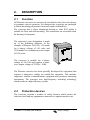
The converter has a robust aluminium housing to class IP21 which is
suitable for floor and wall mounting. The connections are accessible from
the housing’s front panel.
The converter’s type designation is made
up of the following elements: in the
example of Phoenix 110/1500, 110 stands
for a battery voltage of 110 volts, and
1500 stands for a continuous power output
of 1500 watts.
The converter is suitable for a battery
voltage of 110 Vdc and supplies a sinuswave output voltage of 230Vac / 50Hz.
The Phoenix converter has been specially developed for equipment that
requires a sinus-wave voltage for trouble-free operation. This includes
computers, satellite communications equipment and precision measuring
instruments. The converter uses high-frequency switching technology
which results in a high-efficiency system.
2.2
Protection devices
The converter contains a number of safety features which protect the
converter itself and any equipment connected to it against incorrect use.
Phoenix 110/1500 user manual
victron energie
7
Short-circuit protection
• The converter’s output is protected against short circuits. In the
event of a short circuit the output voltage falls to approx. 0 volts.
Once the short circuit has been removed, the converter resumes
operation as specified. For this reason incorporation of a fuse in the
converter’s output circuit is unnecessary.
Overload protection
• The converter can temporarily deliver a higher output than the
continuous output. If more power is demanded for an extended
period, the converter will shut down at its temperature threshold. If
more power is demanded than the converter can supply, the converter
will be restricted to its maximum output.
Thermal protection
• The internal temperature of the converter is measured continuously. If
the internal temperature rises too high (for example, because of an
extremely high ambient temperature), the converter automatically
shuts down and the “temp.” LED lights up. The converter starts up
again as soon as the temperature has fallen sufficiently.
Input voltage protection
• If the input voltage is too low, the converter automatically shuts down
and the “low batt.” LED lights up. The converter automatically starts
up again once the input voltage has risen sufficiently.
• If the input voltage is too high, the converter automatically shuts
down. The converter automatically starts up again once the input
voltage has fallen sufficiently. Please refer to section 6 for the precise
values.
8
victron energie
Phoenix 110/1500 user manual
3.
INSTRUCTIONS FOR USE
3.1
Installation
Make sure that the connection cables are deenergised. THE BATTERY VOLTAGE IS NOT
SAFE TO TOUCH.
The Phoenix converter should be installed in a dry, well ventilated area.
Ensure adequate ventilation in view of the heat produced by the
converter. When the ambient temperature is high, the maximum power
that can be supplied will decrease, efficiency will be reduced and the
service life shorter.
The converter can be mounted in any position. It is recommended,
however, that the unit be mounted vertically. This position provides
optimum cooling. The converter is suitable for wall or floor mounting.
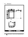
The converter dimensions and the positions of the attachment holes are
given in section 6. The distance between the converter and the battery
must be as short as possible and should not exceed 6 metres. To deenergise the connection bolts, it is recommended that the converter
should be connected not directly to the battery but via a two-pole switch.
The switch may also possibly be replaced by a fuse (knife fuse) which
can be safely removed to interrupt the power to the converter. Make sure
that the fuse and the safety earth are not connected to the same battery
pole.
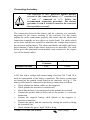
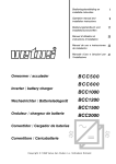
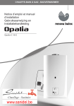
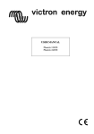
Proceed as follows to gain access to
the converter connection points:
• Unscrew the four screws on the
front panel of the housing, see
Fig. 1.
• Carefully remove the front panel
of the housing. The front panel
remains connected to the printed
circuit board via a ribbon cable.
• Remove the air conduction panel by
unscrewing the wing nuts, see Fig. 2.
Phoenix 110/1500 user manual
Fig. 1
victron energie
9
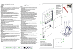
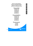
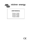
•
The connection points are located on the printed circuit board in the
converter, see Fig. 3.
Fig. 3
Fig. 2
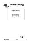
Earth connection
For safety reasons the converter housing must be
earthed.
The converter housing has an earth screw on the underside, see Fig. 4.
The connection is as follows:
• Mount the supplied cable lug on a cable
with a core diameter of 2.5 mm².
• Screw the cable with the cable lug to the
earth screw.
• On a boat: connect the other end of the
cable to the earth plate or the hull.
• On land: connect the other end of the
cable to the earth of the electricity mains.
• With mobile applications (car, caravan
etc.): connect the other end of the cable
Fig. 4
to the vehicle chassis.
10
victron energie
Phoenix 110/1500 user manual
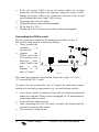
Connecting the battery
The converter is NOT protected against polarity
reversal of the connected battery (“+” connected to
“-” and “-” connected to “+”). Follow the
recommended connection procedure. The factory
guarantee is void if a fault is caused to the converter
due to polarity reversal.
The connections between the battery and the converter are extremely
important for the correct working of the converter. For this reason
tighten the cable connections properly and ensure that the cables and
connection terminals are not subject to tensile loads. Use cables which
are as short and thick as possible to minimise the voltage drop between
the converter and the battery. The shorter and thicker the cables, the lower
their resistance. Cables longer than 6 metres are not advisable. The table
below gives the minimum recommended cross-sections for the copper
core of the battery cables.
Phoenix 110/1500
Shorter than
1.5 metres
2
6 mm
1.5 - 6 metres
2
10 mm
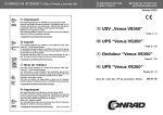
A DC fuse with a voltage and current rating of at least 150 V and 30 A
must be incorporated in the battery connection. The battery connections
are located on the printed circuit board in the converter, see Fig. 5. The
battery cables must be connected to the battery connections as follows:
• Check whether the battery cables are de-energised.
• Check whether the converter is switched off.
• Check that the fuse(s) are not present on the printed circuit board.
• Connect the positive battery cable (red) to the positive (+) converter
connection.
• Connect the negative battery cable (black) to the negative (-)
converter connection.
• Connect the battery and the converter by closing the switch or fitting
the (external) fuse.
• Check whether the green “right” LED is lit up.
Phoenix 110/1500 user manual
victron energie
11
•
•
•
•
•
If the red “wrong” LED is lit up, the battery cables are wrongly
connected. First de-energise the converter using the switch or fuse.
Change the battery cables over. Switch the converter back on and
check whether the green “right” LED is lit up.
De-energise the converter again.
Tighten the battery connections thoroughly.
Fit the fuse (2 x 15 A).
Connect the 230 Vac cable, as described in the next paragraph.
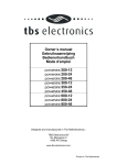
Connecting the 230Vac cable
The AC connector is located on the printed circuit board, see Fig. 5.
The 230Vac cable must be connected as follows:
• Check whether the
converter
is
switched off.
• Connect
the
230Vac unit to the
AC connector via a
three-core
cable
with a flexible core
and
a
core
diameter of 1.5
mm² to 2.5mm2.
Fig. 5
The connecting points are clearly coded. From left to right: “L1” (live),
“N” (neutral) and “PE” (earth).
To protect the unit connected to the AC output, the earth must comply
with the relevant safety requirements (e.g. an earth-leakage switch).
•
•
•
•
12
If no remote control is connected, locate the air conduction panel and
tighten the wing nuts. Please refer to paragraph 4.1 for information on
connecting a remote control.
Locate the front panel correctly.
After connecting the 230 Vac cable, reconnect the battery and the
converter by means of the switch.
The converter is ready for use.
victron energie
Phoenix 110/1500 user manual
3.2
Operation
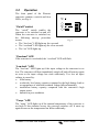
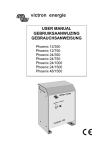
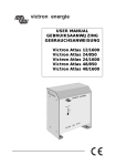
The front panel of the Phoenix
converter contains a switch and four
LEDs, see Fig. 6.
“On/off” switch
The “on/off” switch enables the
converter to be switched on and off.
When the converter is switched on,
the following start-up procedure
occurs:
• The “low batt.” LED lights up for a second.
• The “overload” LED lights up for a few seconds.
• The “on” LED lights up.
Fig. 6
“Overload” LED
If the converter is overloaded, the “overload” LED will flash.
“Low batt.” LED
The “low batt.” LED lights up if the input voltage to the converter is too
low. The converter will then immediately switch off and will start up again
as soon as the input voltage has risen sufficiently. Too low an input
voltage is caused by:
• a flat battery
• a relatively low battery capacity compared to the high battery load as
a consequence of which the terminal voltage falls substantially
• insufficient battery capacity compared with the converter’s high
output power
• batteries in poor condition.
“Temp.” LED
The “temp.” LED lights up if the internal temperature of the converter is
too high. If this situation occurs, the converter switches off. It starts up
again as soon as the temperature has fallen sufficiently.
Phoenix 110/1500 user manual
victron energie
13
3.3
Maintenance
Phoenix converters require no specific maintenance. An annual check of
the electrical connections is all that is needed. Keep the unit dry and as
clean as possible.
14
victron energie
Phoenix 110/1500 user manual
4.
OPTIONS
4.1
Connecting a remote control
Phoenix converters can be switched on and off with the aid of the remote
control. The remote control can also be used for remotely connecting the
four indicator LEDs.
The leads of the remote control must be connected to the remote control
connector, see Fig. 7. Before connecting the leads, check that the converter
has been de-energised (green LED is not lit up).
A hole must be made in the
closed
grommet in the converter’s
base plate to route the leads
to the outside.
Fig. 7
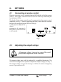
4.2
Adjusting the output voltage
A dangerous voltage is present on some of the metal
parts of the components in the converter.
The output voltage may only be adjusted by a qualified electrician. The
converter housing must be opened to adjust the output voltage, see Fig. 8.
The output voltage is set in the factory to 230Vac. It can be changed by
means of potentiometer P4.
Phoenix 110/1500 user manual
victron energie
15
Fig. 8
16
victron energie
Phoenix 110/1500 user manual
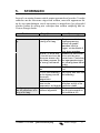
5.
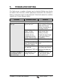
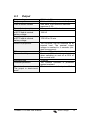
TROUBLESHOOTING
If a fault occurs, a number of points can be checked. Before any checks
are made on the converter, all the equipment connected to the converter’s
battery connections must be disconnected. If the fault cannot be rectified,
consult your Victron Energie dealer.
Problem
Possible cause
Solution
The converter does not The input voltage is too Make sure that the
high or too low.
input voltage is brought
start up:
within the correct
values, see section 6
for these values.
Switch the converter off
The plus (+) and the
and connect the
minus (-) of the
battery correctly.
batteries and the
Check the input fuses
converter do not
and replace them if
correspond, and the
necessary.
“wrong” LED is lit up.
The converter is not
Set the switch to “on”.
on.
Remove part of the
Too high a load has
been connected to the load.
converter’s output.
Allow the converter to
The converter is too
cool down and check
hot, and the
“temperature” LED is lit whether the fans are
running.
up.
Set potentiometer P4
The output voltage of Potentiometer P4 is
wrongly adjusted.
to the correct value,
the converter is too
see section 4.2.
high or too low:
Phoenix 110/1500 user manual
victron energie
17
6.
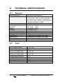
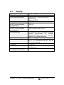
TECHNICAL SPECIFICATIONS
6.1
General
Ventilation system
Thermal protection
Relative humidity
Emission
Immunity
Safety
Housing
Colour
Dimensions (h x w x d)
Weight
Output 230 Vac
Input 110 Vdc
Housing earth
Remote control
6.2
Input
Input voltage nominal
Input voltage range
Switch-on voltage (low)
Switch-on voltage (high)
Switch-off voltage (low)
Switch-off voltage (high)
Voltage ripple maximum
Input current nominal
Input current maximum
No load
Input fuses
18
Internal forced convection
The internal temperature is measured
continuously. The converter switches off
as soon as the maximum temperature is
exceeded. When the temperature falls, the
converter switches on again.
0-95 %
EN 55014 (1993)
EN 55104 (1995)
EN 60950-4 (1991)
Aluminium, IP21
Blue (RAL 5012), epoxy
352 x 250 x 205 mm
8 kg
Connections on printed circuit board
Connections on printed circuit board
M4 screw
Connections on printed circuit board
victron energie
110.0 Vdc
83.0 – 148.5 Vdc
95.0 Vdc
148.0 Vdc
83.0 Vdc
148.5 Vdc
5%
17 A
25 A
11 W
2 x 15 A
Phoenix 110/1500 user manual
6.3
Output
Output voltage
Frequency
Form of output voltage
Power factor (cos phi)
Nominal power
at 25°C and at nominal
battery voltage
Temporary max. power
at 25°C and at nominal
battery voltage
Switch-on properties
Efficiency
Dynamic stability
Recovery time
Overload protection
Short-circuit current
The output is short-circuitproof.
230 Vac +/- 5%
50 Hz +/- 0.5% (crystal-controlled)
Sine wave, total harmonic distortion:
maximum 2.5%
0.9 capacitive to 0.4 inductive
1500 W
1700 W for 30 min
The converter can be switched on at
nominal load. The nominal output
voltage is reached in 4 seconds (incl.
start-up sequence).
Minimum 80% at nominal load
Maximum 10% short-term deviations
when switching on and off at 50% of
the nominal load
½ period
The Phoenix converter is protected
against overload.
Short-circuit current of output: 1.3 A
Phoenix 110/1500 user manual
victron energie
19
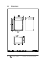
6.4
20
Dimensions
victron energie
Phoenix 110/1500 user manual
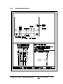
6.5
Connection diagram
Phoenix 110/1500 user manual
victron energie
21
GEBRUIKSAANWIJZING PHOENIX 110/1500
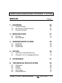
INHOUD
Pagina
1. INLEIDING
1.1
1.2
1.3
25
Victron Energie
De Phoenix sinusomvormer
Waarschuwingen
25
25
25
2. BESCHRIJVING
2.1
2.2
27
Werking
Beveiligingen
27
27
3. GEBRUIKSRICHTLIJNEN
3.1
3.2
3.3
29
Installatie
Bediening
Onderhoud
29
33
34
4. OPTIES
4.1
4.2
35
Aansluiten afstandsbediening
Afregelen van de uitgangsspanning
35
35
5. STORINGEN
37
6. TECHNISCHE SPECIFICATIES
38
6.1
6.2
6.3
6.4
6.5
Algemeen
Ingang
Uitgang
Afmetingen
Aansluitschema
Phoenix 110/1500 gebruiksaanwijzing
38
38
39
40
41
victron energie
23
24
victron energie
Phoenix 110/1500 gebruiksaanwijzing
1.
INLEIDING
1.1
Victron Energie
Victron Energie is internationaal bekend door het ontwerpen en het
fabriceren van elektrische energievoorzieningssystemen. Dit is te danken
aan de voortdurende aandacht die de ontwikkelingsafdeling besteedt aan
productonderzoek en het toepassen van nieuwe technologieën in haar
producten.
Victron Energie systemen zorgen voor een kwalitatief hoogwaardige
energie- voorziening op plaatsen waar geen permanente aansluiting op het
elektriciteitsnet aanwezig is.
Een “stand alone” automatisch werkend energievoorzieningssysteem kan
bestaan uit: Een Victron Energie omvormer, een Victron Energie
acculader, eventueel een Victron Energie Mains Manager en accu's met
voldoende capaciteit.
1.2
De Phoenix sinusomvormer
Deze handleiding beschrijft de installatie, de werking en de praktische
toepassing van de Phoenix sinusomvormer. Bovendien wordt in deze
handleiding ingegaan op de beveiligingsvoorzieningen en de technische
specificaties van de omvormer.
1.3
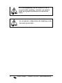
Waarschuwingen
De omvormer is NIET beveiligd tegen ompoling van
de aangesloten accu ("+" aangesloten op "-" en "-"
aangesloten op "+"). Volg de aansluitprocedure.
De fabrieksgarantie vervalt wanneer er door
ompoling een defect aan de omvormer is ontstaan.
De omvormer wordt ernstig beschadigd wanneer op
de 230Vac uitgang een andere wisselspanning wordt
gezet (bvb. van een generator). Deze beschadiging
valt niet onder de fabrieksgarantie.
Phoenix 110/1500 gebruiksaanwijzing
victron energie
25
De accuklemspanning van de Phoenix 110Vdc is
een gevaarlijke spanning. Aanraken van metalen
delen op de print kan leiden tot een elektrische
schok.
In verband met veiligheid moet de behuizing van de
omvormer geaard zijn.
26
victron energie
Phoenix 110/1500 gebruiksaanwijzing
2.
BESCHRIJVING
2.1
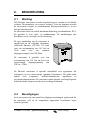
Werking
Alle Phoenix omvormers worden uitgebreid getest voordat ze de fabriek
verlaten. Dit garandeert een correcte werking. Voor het transport worden
de omvormers verpakt in schokdempend polystyreenschuim en in een
stevige kartonnen doos.
De omvormer heeft een solide aluminium behuizing, beschermklasse IP21,
die geschikt is voor vloer- en wandmontage. De aansluitingen zijn
bereikbaar via de voorzijde van de behuizing.
De type aanduiding van de omvormer is
opgebouwd uit de volgende elementen,
voorbeeld: Phoenix 110/1500. 110 staat
voor een accuspanning van 110 Volt en
1500
staat
voor
een
continue
uitgangsvermogen van 1500 Watt.
De omvormer is geschikt voor een
accuspanning van 110 Vdc en levert een
sinusvormige
uitgangsspanning
van
230Vac / 50Hz.
De Phoenix omvormer is speciaal ontwikkeld voor apparatuur die
storingsvrij op een sinusvormige spanning functioneert. Dit geldt onder
andere voor computers, satellietcommunicatie apparatuur en
precisiemeetinstrumenten. De omvormer maakt gebruik van hoogfrequente
schakeltechniek, hetgeen resulteert in een hoog rendement.
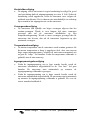
2.2
Beveiligingen
In de omvormer zijn een aantal beveiligingsvoorzieningen ingebouwd die
de omvormer zelf en de aangesloten apparatuur beschermen tegen
verkeerd gebruik.
Phoenix 110/1500 gebruiksaanwijzing
victron energie
27
Kortsluitbeveiliging
• De uitgang van de omvormer is tegen kortsluiting beveiligd. In geval
van kortsluiting daalt de uitgangsspanning tot circa. 0 Volt. Zodra de
kortsluiting wordt opgeheven, werkt de omvormer weer volgens de
geldende specificaties. Het is daarom niet noodzakelijk een zekering
op te nemen in het uitgangscircuit van de omvormer.
Vermogensbeveiliging
• De omvormer kan tijdelijk een hoger vermogen afgeven dan het
continu-vermogen. Wordt er voor langere tijd meer vermogen
gevraagd dan zal de omvormer afschakelen op zijn
temperatuurbegrenzing. Wordt er meer vermogen gevraagd dan de
omvormer kan leveren, dan zal de omvormer begrenzen op zijn
maximaal vermogen.
Temperatuurbeveiliging
• De interne temperatuur van de omvormer wordt continu gemeten Als
de interne temperatuur te hoog is opgelopen (bvb. door een extreem
hoge omgevingstemperatuur), schakelt de omvormer automatisch uit
en gaat de “temp.” led branden. Zodra de temperatuur voldoende is
gedaald, start de omvormer op.
Ingangsspanningsbeveiliging
• Zodra de ingangsspanning een te lage waarde bereikt wordt de
omvormer automatisch uitgeschakeld en de “low batt.” led gaat
branden. De omvormer start automatisch op wanneer de
ingangsspanning voldoende is gestegen.
• Zodra de ingangsspanning een te hoge waarde bereikt wordt de
omvormer automatisch uitgeschakeld. De omvormer start automatisch
op wanneer de ingangsspanning voldoende is gedaald. Zie voor de
exacte waarden hoofdstuk 6.
28
victron energie
Phoenix 110/1500 gebruiksaanwijzing
3.
GEBRUIKSRICHTLIJNEN
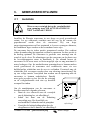
3.1
Installatie
Wees ervan overtuigd dat op de aansluitkabels
geen spanning staat. DE ACCUSPANNING IS
NIET AANRAAK VEILIG.
Installeer de Phoenix omvormer in een droge en goed geventileerde
ruimte. Let op voldoende ventilatie met het oog op de warmte die
geproduceerd wordt door de omvormer. Bij een hoge
omgevingstemperatuur zal het maximaal te leveren vermogen afnemen,
het rendement lager worden en de levensduur korter zijn.
De omvormer kan in iedere positie gemonteerd worden. Het verdient
echter de aanbeveling het apparaat verticaal te monteren. In deze positie is
de koeling optimaal. De omvormer is geschikt voor montage aan de
wand of op de vloer. De afmetingen van de omvormer en de plaats van
de bevestigingsgaten staan in hoofdstuk 6. De afstand tussen de
omvormer en de accu moet zo klein mogelijk zijn en mag maximaal 6
meter bedragen. Om de aansluitbouten spanningsloos te kunnen maken
wordt geadviseerd de omvormer niet rechtstreeks maar via een
dubbbelpolige schakelaar met de accu te verbinden. Eventueel mag de
schakelaar ook vervangen worden door een zekering (meszekering) die
op een veilige manier verwijderd kan worden om de spanning naar de
omvormer te kunnen onderbreken. Daarbij
moet gelet worden op het feit dat de zekering
en de veiligheidsaarde zich niet op dezelfde
accupool bevinden.
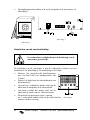
Om de aansluitpunten van de omvormer te
bereiken moet het volgende gebeuren:
• Draai de vier schroeven aan de voorzijde
van de behuizing los, zie afbeelding 1.
• Schuif het front van de behuizing
voorzichtig weg. Het front blijft via
een bandkabel verbonden met de printplaat
• Verwijder de luchtgeleidingsplaat door de
vleugelmoeren los te draaien, zie afbeelding 2.
Phoenix 110/1500 gebruiksaanwijzing
Afbeelding 1
victron energie
29
•
De aansluitpunten bevinden zich op de printplaat in de omvormer, zie
afbeelding 3.
Afbeelding 3
Afbeelding 2
Aansluiten van de aardverbinding
In verband met veiligheid moet de behuizing van de
omvormer geaard zijn.
De behuizing van de omvormer is aan de onderzijde voorzien van een
aardschroef, zie afbeelding 4. De aansluiting is als volgd:
• Monteer het meegeleverde kabelschoentje
aan een kabel met een aderdoorsnede van
2,5mm2.
• Schroef de kabel met het kabelschoentje aan
de aardschroef.
• Op een boot: verbind het andere eind van de
kabel met de aardplaat of de scheepshuid.
• Aan land: verbind het andere eind van de
kabel met de aarde van het elektriciteitsnet.
• Bij mobiele toepassingen (auto, caravan,
etc.): verbind het andere eind van de kabel met het Afbeelding 4
chassis van het voertuig.
30
victron energie
Phoenix 110/1500 gebruiksaanwijzing
Aansluiten van de accu
De omvormer is NIET beveiligd tegen ompoling van
de aangesloten accu ("+" aangesloten op "-" en "-"
aangesloten op "+"). Volg de aansluitprocedure.
De fabrieksgarantie vervalt wanneer er door
ompoling een defect aan de omvormer is ontstaan.
De aansluitingen tussen de accu en de omvormer zijn uitermate
belangrijk voor de goede werking van de omvormer. Draai daarom de
kabelverbindingen goed aan en let op dat er geen trekkracht op de kabels
en de aansluitklemmen staat. Gebruik zo kort en zo dik mogelijke kabels
om het spanningsverlies tussen de omvormer en de accu tot een minimum
te beperken. Hoe korter en dikker de kabels zijn, des te geringer is hun
weerstand. Kabels langer dan 6 meter worden afgeraden. Onderstaande
tabel geeft het aanbevolen minimum doorsneden voor de koperkern van de
accukabels.
Phoenix 110/1500
korter dan 1,5
meter
2
6 mm
1,5 - 6 meter
2
10 mm
Het is verplicht om bij de accu-aansluiting tussen accu en omvormer een
DC-zekering op te nemen met een nominale spanning en stroom van
minimaal 150V en 30A. De accu-aansluitingen bevinden zich op de
printplaat in de omvormer, zie afbeelding 5. De accukabels moet als volgt
op de accu-aansluitingen aangesloten worden:
• Controleer of de aansluitkabels spanningsloos zijn.
• Controleer of de omvormer uitgeschakeld is.
• Controleer of de zekering(en) niet op de printplaat aanwezig zijn.
• Sluit de positieve accukabel (rood) op de positieve (+)
omvormeraansluiting aan.
• Sluit de negatieve accukabel (zwart) op de negatieve (-)
omvormeraansluiting aan.
• Sluit de verbinding tussen accu en omvormer middels het sluiten van
de schakelaar of het plaatsen van de (externe) zekering.
• Controleer of de groene led “right” brandt.
Phoenix 110/1500 gebruiksaanwijzing
victron energie
31
•
•
•
•
•
Wanneer de rode led “wrong” brandt zijn de accukabels verwisseld.
Maak eerst de omvormer spanningsloos met behulp van de schakelaar
of zekering. Verwissel de kabels. Zet spanning op de omvormer en
controleer of de groene led “right” brandt.
Maak de omvormer weer spanningsloos.
Draai de accuverbindingen goed aan.
Plaats de zekering 2x15A.
Sluit de 230 Vac kabel aan, zie hiervoor volgende paragraaf.
Aansluiten van de 230Vac kabel
De AC-connector bevindt zich op de printplaat, zie afbeelding 5.
De 230Vac kabel moet als volgt aangesloten worden:
• Controleer of de omvormer uit staat.
• Sluit
de
230Vac
apparatuur aan op de
AC-connector via een
drie-aderige kabel met
een soepele kern en
een kerndoorsnede van
1,5mm2 tot 2,5mm2.
De aansluitpunten zijn
duidelijk gecodeerd.
Van links naar rechts:
"L1" (fase), "N" (nul) en "PE" (aarde).
Afbeelding 5
Voor de veiligheid van de aangesloten apparatuur op de AC-uitgang
moet de aarding voldoen aan de daarvoor geldende veiligheidseisen
(bvb. een aardlekschakelaar).
•
•
•
•
32
Als geen afstandbediening wordt aangesloten, plaats de
luchtgeleidingsplaat en draai de vleugelmoeren vast. Voor het
aansluiten van afstandbediening zie paragraaf 4.1.
Plaats het front in de juiste positie.
Na aansluiten van de 230 Vac kabel, herstel de verbinding tussen
accu en omvormer middels de schakelaar.
De omvormer is klaar voor gebruik.
victron energie
Phoenix 110/1500 gebruiksaanwijzing
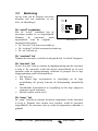
3.2
Bediening
Op het front van de Phoenix omvormer
bevinden zich een schakelaar en vier
led’s, zie afbeelding 6.
De “on/off” schakelaar
Met de “on/off” schakelaar kan de
omvormer worden in- en uitgeschakeld.
Wanneer
de
omvormer
wordt
ingeschakeld, vindt de volgende
opstartprocedure plaats:
• De “low batt.” led licht een seconde op.
• De “overload” led licht een aantal seconden op.
• De “on” led licht op.
Afbeelding 6
De “overload” led
Wanneer de omvormer overbelast wordt gaat de led "overload" knipperen.
De “low batt.” led
De led “low batt” licht op wanneer de ingangsspanning naar de omvormer
te laag is. De omvormer wordt dan meteen uitgeschakeld en zal weer
opstarten zodra de ingangsspanning voldoende is gestegen. Een te lage
ingangsspanning wordt veroorzaakt door:
• Een lege accu.
• Een relatief lage accucapaciteit in vergelijking tot de hoge
accubelasting als gevolg waarvan de klemspanning aanmerkelijk
daalt.
• Onvoldoende accucapaciteit in vergelijking tot het hoge afgegeven
vermogen van de omvormer.
• Slechte conditie van de accu's.
De “temp.” led
De “temp.” led licht op wanneer de interne temperatuur van de omvormer
te hoog is. Wanneer deze situatie zich voordoet, wordt de omvormer
uitgeschakeld. De omvormer start op zodra de temperatuur voldoende is
gedaald.
Phoenix 110/1500 gebruiksaanwijzing
victron energie
33
3.3
Onderhoud
De Phoenix omvormers vereisen geen specifiek onderhoud. Het volstaat
de elektrische verbindingen eenmaal per jaar te controleren. Voorkom dat
de eenheid vochtig wordt en houd de eenheid zo schoon mogelijk.
34
victron energie
Phoenix 110/1500 gebruiksaanwijzing
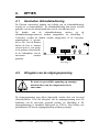
4.
OPTIES
4.1
Aansluiten afstandsbediening
De Phoenix omvormers kunnen met behulp van de afstandsbediening
worden in- en uitgeschakeld. De afstandsbediening kan tevens worden
gebruikt voor het op afstand aansluiten van de vier indicatie led’s.
De
draden
van
de
afstandsbediening
moeten
op
de
afstandsbedieningsconnector worden aangesloten, zie afbeelding 7.
Controleer voordat de draden worden aangesloten of de omvormer
spanningsloos is (groene
led is uit). Om de draden
buiten de kast te kunnen
voeren moet er een gaatje
in de gesloten doorvoertule
in de bodemplaat van de
omvormer
worden
gemaakt.
Afbeelding 7
4.2
Afregelen van de uitgangsspanning
Er staat een gevaarlijke spanning op sommige
metalen delen van de componenten in de
omvormer.
De uitgangsspanning mag alleen afgeregeld worden door een bevoegd
elektrotechnicus. Voor het afregelen van de uitgangsspanning moet de
behuizing van de omvormer geopend worden, zie afbeelding 8. De
uitgangsspanning is standaard afgeregeld op 230Vac. Met behulp van
potentiometer P4 kan de uitgangsspanning worden gewijzigd.
Phoenix 110/1500 gebruiksaanwijzing
victron energie
35
Afbeelding 8
36
victron energie
Phoenix 110/1500 gebruiksaanwijzing
5.
STORINGEN
In geval van storing kunnen enkele punten gecontroleerd worden. Voordat
controles aan de omvormer uitgevoerd worden, moet alle apparatuur die
op de accu-aansluitingen van de omvormer is aangesloten, los gekoppeld
worden. Indien de storing niet verholpen kan worden raadpleeg dan uw
Victron Energie dealer.
Probleem
Mogelijke oorzaak
Oplossing
De omvormer start niet De ingangsspanning is Zorg ervoor dat de
te hoog of te laag.
ingangsspanning
op:
binnen de goede
waarden komt te
liggen, zie hoofdstuk 6
voor deze waarden.
De plus (+) en de min Schakel de omvormer
(-) van de accu’s en de uit en sluit de accu
omvormer komen niet correct aan. Controleer
met elkaar overeen. En de ingangszekeringen
de “wrong” led brandt. en vervang deze indien
nodig.
De omvormer staat niet Zet de schakelaar op
aan.
“on”.
Er is te veel belasting Ver wijder een deel van
op de uitgang van de de belasting.
omvormer
aangesloten.
Laat de omvormer
De omvormer is te
afkoelen en kijk of de
warm en de
temperatuur led brandt. ventilator draait.
De uitgangsspanning De potentiometer P4 is Stel potentiometer P4
op de juiste waarde in,
van de omvormer is te verkeerd afgesteld.
zie hoofdstuk 4.2.
hoog of te laag:
Phoenix 110/1500 gebruiksaanwijzing
victron energie
37
6.
TECHNISCHE SPECIFICATIES
6.1
Algemeen
Ventilatietechniek
Temperatuur beveiliging
Relatieve vochtigheid
Emissie
Immuniteit
Veiligheid
Behuizing
Kleur
Afmetingen (h x b x d)
Gewicht
Uitgang 230 Vac
Ingang 110 Vdc
Kastaarde
Afstandsbediening
6.2
Interne geforceerde convectie
De interne temperatuur wordt continu
gemeten. De omvormer schakelt uit zodra
de
maximale
temperatuur
wordt
overschreden. Wanneer de temperatuur is
gedaald, schakelt de omvormer aan.
0-95 %
EN 55014 (1993)
EN 55104 (1995)
EN 60950-4 (1991)
Aluminium, IP21
Blauw (RAL 5012), epoxy
352 x 250 x 205 mm
8 kg
Aansluitingen op printplaat
Aansluitingen op printplaat
Schroef M4
Aansluitingen op printplaat
Ingang
Ingangsspanning nominaal
Ingangsspanning bereik
Inschakelspanning (laag
Inschakelspanning (hoog)
Uitschakelspanning (laag)
Uitschakelspanning (hoog)
Maximaal toelaatbare
spanningsrimpel
Ingangsstroom nominaal
Ingangsstroom maximaal
Nullast
Ingangszekeringen
17 A
25 A
11 W
2 x 15 A
38
Phoenix 110/1500 gebruiksaanwijzing
victron energie
110,0 Vdc
83,0 – 148,5 Vdc
95,0 Vdc
148,0 Vdc
83,0 Vdc
148,5 Vdc
5%
6.3
Uitgang
Uitgangsspanning
Frequentie
Vorm uitgangsspanning
Vermogensfactor (cos phi)
Nominaal vermogen
bij 25°C en bij nominale
accuspanning
Tijdelijk max. vermogen
bij 25°C en bij nominale
accuspanning
Inschakelgedrag
Rendement
Dynamische stabiliteit
Hersteltijd
Overbelastingsbeveiliging
Kortsluitstroom
De uitgang is kortsluitvast.
230 Vac +/- 5%
50 Hz +/- 0,5% (kristalgestuurd)
Sinusvormig, Totale harmonische
vervorming:
Maximaal 2,5%
0,9 capacitief tot 0,4 inductief
1500 W
1700 W gedurende 30 min
De omvormer kan bij nominale belasting
worden ingeschakeld. De nominale
uitgangsspanning wordt in 4 seconden
bereikt (incl. Opstartvolgorde).
Minimaal 80% bij nominale belasting
Maximaal 10% kortstondige afwijkingen
bij in- en uitschakelen bij 50% van de
nominale belasting
½ periode
De Phoenix omvormer is beveiligd tegen
overbelasting.
Kortsluitstroom uitgang: 1,3 A
Phoenix 110/1500 gebruiksaanwijzing
victron energie
39
6.4
40
Afmetingen
victron energie
Phoenix 110/1500 gebruiksaanwijzing
6.5
Aansluitschema
Phoenix 110/1500 gebruiksaanwijzing
victron energie
41