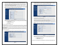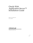
1
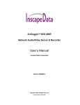
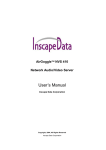
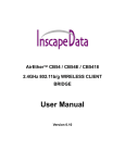
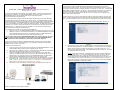
ACCESS POINT MODE CONFIGURATION – SB54
AIRETHERTM SB54/BR54/SC54 DUAL BAND WIRELESS SERIES
QUICK INSTALL GUIDE
This product is recommended to be installed by a professional installer. This Guide is prepared for basic
Access Point mode installation. For other detailed installation, please refer to the User’s Manual or the
AIRETHER SB54, BR54, or SC54 Application Notes from Inscape Data’s web site,
http://www.inscapedata.com/supportnotes.htm
Prior to setup, please take some time to consider the wireless network topology and how the AIRETHER
SB54, BR54, and SC54 Series will integrate into your existing network. The AIRETHER SB54 and BR54
Dual Band Wireless Base Station can be configured to the one of the following modes: Access Point, Bridge,
AP Client, and CPE router. The AIRETHER SC54 can be used as Dual Band Wireless Client Bridge, i.e.,
CPE, only. Both SB54/SC54 come with an integrated 2.4GHz panel antenna. The BR54 offers an integrated
5GHz antenna. You will need a 5GHz external antenna, if you would like to use the 5GHz frequency band
for SB54 and SC54. A 2.4GHz external antenna if using BR54. For wide selection of antenna offering
please visit http://www.inscapedata.com/antennas.htm.
AND
BR54
In Access Point (AP) mode, the AIRETHER SB54 and BR54 allows multiple wireless client bridges to
connect and form a wireless network. The AP relays data between wired and wireless devices. For quick
setup purposes, setup the AP with an IP address that does not conflict with your LAN or PC. The AIRETHER
SB54 and BR54‘s default IP address is “192.168.1.20”. It is recommended to change the unit’s IP address
which best accommodate your setup. Not changing the default IP address of the AP may result in IP
address conflict with other network devices on the LAN. If you are uncertain of which IP address to use,
please consult a network administrator.
To initially configure your AP, open an Internet explorer page and type the default address ‘192.168.1.20’ in
the URL. You will be prompted to enter a password to access the configuration and the default password is
‘root’. You will be prompted to enter a User ID to access the configuration and the default User ID is ‘root’.
1.
Once authenticated, the administrator menu System Information will appear. See figure 2.
2.
Select the top menu item “Network -> Wireless Settings” on the left hand side to customize the
AP’s SSID, Operating frequency, and signal modulation. It is recommended to use a descriptive
SSID to identify the wireless coverage area provided by your unit and RF channel 1, 6, or 11.
Click Apply after changing the settings. Your AIRETHER unit will reboot at this point. See Figure
3 for graphical reference of this section.
Here is a starting point to consider for your wireless network application:
1.
WIFI AREA COVERAGE - One AIRETHER SB54 or BR54 per coverage area configured in AP mode
2.
WISP POINT-TO-MULTIPOINT fixed wireless infrastructure - One AIRETHER SB54 with one SA1218,
2.4GHz adjustable gain sector antenna or one SA5G1218, 5GHz 12 to 18dBi adjustable gain
sector antenna and multiple SC54 Customer Premises Equipments (CPE).
NOTE: The factory default setting of AIRETHER SB54 & BR54 series product is AP mode. If you are
not familiar with the network configuration, we recommend first using the AIRETHER SB54/SC54
series in default mode (Access Point Mode) to familiarize yourself with the equipment.
It is highly recommended to configure the AIRETHER SB54, BR54, and SC54 series equipment before
integrating it into your network. Please refer to Figure 1 for configuration preparation. The AIRETHER
SB54/SC54 is shown in Figure 1 as example.
CONFIGURATION PREPAR ATION
1)
2)
3)
4)
5)
Connect a 2.4GHz or a 5GHz antenna into the antenna port of AIRETHER SB54/SC54. If using
AIRETHER SB54, BR54, and SC54 with an integrated antenna, skip to 2.
Connect a length of straight through CAT V or equivalent network cable between the AIRETHER
SB54, BR54, and SC54 series and “ODU” port on the PoE injector.
Connect an EIA568B terminated straight through CAT5 or equivalent network cable, NOT
included in your package, between the “RJ-45” port of the PIP100 PoE injector and your PC or
Network Switch. The 10/100 Ethernet port on the AIRETHER SB54, BR54, and SC54 series
equipment utilizes Auto MDI/MDIX to automatically cross-over the signal if needed.
Recheck the RJ-45 connectors to assure it is securely mated and connected to the correct port
on the PoE injector. A cable tester is the safest way to ensure properly crimped or wired CAT5
Cable. I M P R O P E R C O N N E C T I O N M A Y R E S U L T I N D A M A G E S T O T H E A I R E T H E R
SB54, BR54, OR SC54 SERIES EQUIPMENT OR YOUR PC.
Connect the AC to DC power adapter to the PoE (Power over Ethernet) power supply plug.
Figure 1
- Page 1 AirEther™ is a trademark of Inscape Data Corporation
Figure 2
Example: “Tower1South, BeachCafe, or SCBroadband” are just a few examples of SSID to get
started and channels 1, 6, or 11 are non-overlapping radio channels in the 2.4 GHz spectrum.
For optimal performance, use a 2.4 GHz radio channel that is not used by other AP in the
wireless coverage area of the AIRETHER SB54. In the 5GHz spectrum, there are 4 times more
non-overlapping channels. See the user manual on how to use the Site Survey tool in client
bridge mode to see what 2.4 GHz or 5GHz RF channels are currently occupied. Default SSID is
“AirEther” for SB54/SC54 and “AirEther5” for BR54.
Figure 3
- Page 2 -
3.
4.
5.
Your Access Point is now configured with the basic setting to be implemented as a fixed wireless
Access Point in a WISP environment or WiFi Access Point for mobile wireless client users.
At this point you may test your AIRETHER wireless connectivity with your wireless equipment by
configuring your wireless equipment’s SSID to match the SSID of the Access Point. Minimum
recommended separation between the AIRETHER SB54 or BR54 and wireless client bridge
devices is 10 feet to achieve optimal performance.
To verify your wireless device association with the AIRETHER SB54 or BR54 you have just
configured, login to your AIRETHER unit and open up the web administration GUI menu Wireless
Station list. If both the access point and wireless client bridge are configured correctly, the MAC
address of the wireless client will appear in the Client List. See Figure 4.
8.
Select the menu item “Network” on the top to customize the Client’s SSID, Operating frequency,
and signal modulation. It is recommended to use a descriptive SSID to identify the wireless
coverage area provided by the SC54. Click Apply after changing the settings. Your SC54 unit
will reboot at this point. See Figure 6 for graphical reference of this section.
Figure 6
9.
Figure 4
6.
Additional configuration is recommended to achieve a secure and robust wireless infrastructure.
Please reference to the AIRETHER user manual for the following optional Access Point settings.
a.
Default Admin password change
b.
Wireless Security
c.
Wireless Advanced Settings
d.
MAC Filtering
10.
11.
Your Client is now configured with the basic setting to be implemented as a fixed Customer
Premises Equipment in a WISP environment.
At this point you may test your SC54 for wireless connectivity with your wireless equipment by
configuring your SC54’s SSID to match the SSID of the AP. Minimum recommended separation
between the SC54 and the AP is 10 feet to achieve optimal performance.
To verify your wireless device association with the SC54 you have just configured, login to the
SC54 and open up the web administration GUI menu Wireless Station list. If both the SC54 and
the AP are configured correct, the MAC address of the AP will appear in the Site Survey. See
Figure 7.
SC54 CLIENT BRIDGE CONFIGURATION
The AirEther SC54 can only act as a stand-alone client and only has one mode of operation. The AirEther
SC54‘s default IP address is “192.168.1.20”. It is recommended to change the SC54’s IP address which best
accommodate your setup. Not changing the default IP address of the AP may result in IP address conflict
with other network devices on the LAN. If you are uncertain of which IP address to use, please consult a
network administrator.
To initially configure your SC54 you will need to type the default IP address ‘192.168.1.20 into the URL of an
internet explorer page. This will open the login prompt for user name and password. Enter “root” for user
name and “root” for password.
7.
Once authenticated, the administrator menu System Summary will appear. See figure 5.
Figure 7
12.
Additional configuration is recommended to achieve a secure and robust wireless infrastructure.
Please reference to the SC54 series user manual for the following optional CPE settings.
a.
Default Admin password change
b.
Wireless Security
c.
Wireless Advanced Settings
Please refer to the Users Manual for detailed Repeater, Client Bridge, and Bridge Mode set up.
Figure 5
- Page 3 -
- Page 4 -