1
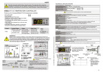
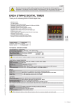
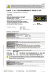
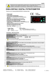
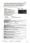
english
TECHNICAL SPECIFICATIONS
Read this document carefully before using this device. The guarantee will be expired by
damaging of the device if you don't attend to the directions in the user manual. Also we don't
accept any compensations for personal injury, material damage or capital disadvantages.
ENVIRONMENTAL CONDITIONS
Ambient/storage temperature
Max. relative humidity
ENDA ET1311 DIGITAL THERMOSTAT
Rated pollution degree
Thank you for choosing ENDA ET1311 temperature controller.
* 34 x 77mm sized.
* On-Off control.
* PTC sensor.
* Adjustable offset for PTC sensor.
* Selectable cooling or heating control.
* The maximum and minimum values of the setpoint
can be limited.
* Output state can be selected On or Off in the case
of probe failure.
* Having CE mark according to European Norms.
ENDA
Safety requirements
NOTE :
OUTPUT
CABLE:
X.X : Cable length
For example: 4.0 = 4.0m
1.5m (standard)
CONTROL
1
2
3
4
5
6
7
8
W
PTC Liquid Probe (S)
9 10 11 12
10
ENDA INDUSTRIAL ELECTRONICS
ENDA INDUSTRIAL ELECTRONICS
ET1311-230-SSR DIGITAL THERMOSTAT
ET1311-12-SSR DIGITAL THERMOSTAT
SN: XXXXXXXXX
5
+
6
7
8
W
9 10 11 12
12V AC/DC ±10%
50/60Hz 3VA
230V AC +10% -20%
50/60Hz 3VA
LOGIC OUT
12V DC 10mA
+
_
R
4
1
2
3
Cable material: Silicone
Please don`t dip the Sensor in liquidity and keep
in dry place !
PTC
SENSOR
Equipment is protected throughout by
_
3
LOGIC OUT
12V DC 10mA
Measurement range: -50 ... +150°C
R 1/8"
R
4
5
6
7
8
W
9 10 11 12
Holding screw 0.4-0.5Nm
NOTE :
Fuse
F 100 mA
250V AC
SUPPLY:
184-253V AC 4
50/60Hz 3VA 5
If necessary use for
the load separate fuse !
Line
Switch
230V AC
Supply
Neutral
Fuse should
be connected.
Cable size: 1,5mm²
Note:
1) Mains supply cords shall meet the
SENSOR INPUT:
requirements of IEC 60227 or IEC 60245.
Pay attention to the color of
2) In accordance with the safety
the PTC probe cables while
regulations, the power supply switch
connecting them to the PTC
shall bring the identification of the
SENSOR input of the device.
relevant instrument and it should be
easily accessible by the operator.
ENDA
ET 1311
2
Flush mounting
clamp
Flush mounting
clamp
Panel Rubber
packing
1
Panel cut-out
OUTPUT
250V AC 8A
RESISTIVE LOAD
2
F = 6mm
Red
Cable length: 1,5 meter
F = 7 mm
SET
230V AC +10% -20%
50/60Hz 3VA
1
White
SN: XXXXXXXXX
PTC
SENSOR
50mm
30mm
34mm
12V AC/DC ±10%
50/60Hz 3VA
R
W
9 10 11 12
8mm
Push out the flush-mounting
clamp in direction 1 as shown
in the figure below. Then, pull
out the clamp in direction 2.
°C
OUT
71mm
29mm
8
up to date: 240805, modification reserved and can be change any time previous notice !
7
OUTPUT
250V AC 8A
RESISTIVE LOAD
OUTPUT
250V AC 8A
RESISTIVE LOAD
230V AC +10% -20%
50/60Hz 3VA
6
70mm
For removing mounting clamps:
SN: XXXXXXXXX
5
Cable material: Silicone
Measurement range: -50 ... +150°C
Depth
85mm
ENDA INDUSTRIAL ELECTRONICS
ET1311-230 DIGITAL THERMOSTAT
4
PTC
SENSOR
Dimensions
W
3
F = 6mm
Red
Cable length: 1,5 meter
While cleaning the device, solvents (thinner, benzine, acid etc.) or corrosive materials must not be used.
PTC
SENSOR
2
White
Suitable for flush-panel mounting.
W77xH34xD70mm
Approx. 160g (after packing the device and a probe)
Self extinguishing plastics
R
PTC
SENSOR
R
1
40mm
SN: XXXXXXXXX
HOUSING
Housing type
Dimensions
Weight
Enclosure material
9 10 11 12
ET1311-12 DIGITAL THERMOSTAT
Single-setpoint control
On-Off control
Adjustable between 1 ... 20°C.
8
ET1311-230 DIGITAL THERMOSTAT
PTC Air Probe (H)
Control type
Control algorithm
Hysteresis
7
ENDA INDUSTRIAL ELECTRONICS
Relay: 250V AC, 8A (for resistive load), NO+NC ; ½ HP 250V AC CosF=0.4 (for inductive load)
COMPRESSOR
Life expectancy for relay
Mechanical 30.000.000 operation; Electrical 100.000 operation.
Note: The relay contacts are suitable for in-line switching of compressors up to 0,5 HP at 240V AC or 1/4 HP at 110V AC.
6
ENDA INDUSTRIAL ELECTRONICS
230V AC +10% -20%, 50/60Hz, or 12V AC/DC ± 10%, 50/60Hz
Max. 3VA
1.5mm² screw-terminal connections.
-50....+150°C
1°C
±1% (of full scale)
EN 61326-1: 1997, A1: 1998, A2: 2001 (Performance criterion B is satisfied for EMC tests.
The device is designed to operate in controlled electromagnetic environment)
EN 61010-1: 2001 (Pollution degree 2, overvoltage category II)
5
Order Code
ET1311-230-H-X.X
ET1311-230-S-X.X
ET1311-230-SSR-H-X.X
ET1311-230-SSR-S-X.X
ET1311-12-H-X.X
ET1311-12-S-X.X
ET1311-12-SSR-H-X.X
ET1311-12-SSR-S-X.X
ET 1311
ATTENTION !
ENDA ET1311 is intended for installation in control panels. Make sure that the device is used
only for intended purpose. The electrical connections must be carried on by a qualified staff
and must be according to the relevant locally applicable regulations. During an installation, all of the
cables that are connected to the device must be free of energy. The device must be protected against
inadmissible humidity, vibrations, severe soiling and make sure that the operation temperature is not
exceeded. The cables should not be close to the power cables or components.
SN: XXXXXXXXX
Supply voltage
Power consumption
Wiring
Scale
Sensitivity
Accuracy
SET
4
12V AC/DC ±10%
ELECTRICAL CHARACTERISTICS
°C
OUT
3
230V AC +10% -20%
Maximum 2000m
Do not use the device in locations subject to corrosive and flammable gasses.
2
Control Output Probe
PTC air probe
Relay
PTC liquid probe
PTC air probe
Logic output
PTC liquid probe
PTC air probe
Relay
PTC liquid probe
PTC air probe
Logic output
PTC liquid probe
Height
1
Supply Voltage
0 ... +50°C/-25 ... +70°C (with no icing)
80%, up to 31°C decreasing linearly 50% at 40°C
According to EN 60529
Front panel : IP60
Rare panel : IP20
Note : 1) Panel thickness
should be maximum
7 mm.
2) If there is no 60mm
free space at the back
side of the device, it
would be difficult to
remove it from the
1/2
ET1311 PROGRAMMING DIAGRAM
Out
LED
°C
OUT
SET
Increment
key
Used for increasing the setpoint value, as well as the parameter when
in programming. When held down for a few seconds, the change rate
accelerates.
Decrement
key
Used for decreasing the setpoint value, as well as the parameter when
in programming. When held down for a few seconds, the change rate
SET
ENDA
Programming
key
ET 1311
Used for adjusting the value of the setpoint in the run mode and for
adjusting the selected parameter in the programming mode.
RUN MODE
Measurement
temperature
Setpoint value
SET
SET
SET
By using
If this key is pressed,
setpoint value appears.
If both
&
and
keys while holding
key,
setpoint value can be adjusted.
keys are pressed and held for 5 seconds, programming mode is entered.
PROGRAMMING MODE
Hysteresis
value
SET
shy
2
If this key is pressed,
hysteresis value
appears.
If this key is pressed,
the lower limit of the
setpoint appears.
-50
150
If this key is pressed,
the upper limit of the
setpoint appears.
keys while holding
0
If this key is pressed,
offset value appears.
By using
and
keys while holding
out
Het
key, the lower limit
of the setpoint can be adjusted to a desired temperature.
Minimum = -50°C Maximum = Value of the SUL parameter.
SET
By using
and
keys while holding
key, the upper limit
of the setpoint can be adjusted to a desired temperature.
Minimum = The value of the SLL parameter Maximum = +150°C.
SET
By using
and
keys while holding
key, the offset
value can be adjusted to a desired value.
SET
Control mode
SET
key, hysteresis
SET
Offset value
SET
ofs
and
Upper limit of
the setpoint
SET
sul
By using
value can be adjusted to a desired temperature.
Minimum = 1°C
Maximum = +20°C.
Lower limit of
the setpoint
SET
sll
SET
By using
and
keys while holding
key, heating (Het)
or cooling (col) mode can be selected.
If this key is pressed,
control mode appears.
SET
eot
State of control
output in the case
of probe failure.
off
If this key is pressed,
the state of the control
output in the case of
probe failure appears.
SET
By using
and
keys while holding
key, the control
output state can be adjusted as off or on for the case of probe failure. If
Eot.= On, the control output is energized during the probe failure.
If eot.= oFF, the control output is de-energised during the probe failure.
If any no key is pressed within 25 seconds, the device will time out back to the run mode. Alternatively, re-energising the device, run mode
is entered.
PFA
SURAN Industrieelektronik
Im Mitteldorf 26 / D-72160 Horb a.N
ERROR MESSAGE
Means the temperature sensor is broken or the
temperature is out of the scale range.
Tel.: +49 (0)7451 / 625 617
Fax: +49 (0)7451 / 625 0650
E-mail : [email protected]
Internet : www.suran-gmbh.de
2/2