1
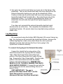
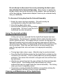
HydroFlush Mini Urinary Disposal System Users Manual Patent Pending Introduction Congratulations on your purchase of the HydroFlush Mini Urinary Disposal System. This product is manufactured from the highest quality components available. If you have purchased any of the option packages available for The HydroFlush System, please refer to their instruction manuals for further assistance. The consumer should carefully plan the installation of this product. Before beginning the installation process please be sure you have received all of the components. Identify all of the components and associated hardware that comprise the HydroFlush System. Becoming familiar with the associated components will aid in installing the HydroFlush System. The HydroFlush Urinary Disposal System allows a person to empty their leg bag with a push of a button. The product’s primary purpose is to give a person freedom and independence. While using the HydroFlush, the user can drink more fluids and not have to worry if someone is available to empty their leg bag. The HydroFlush System uses state of the art electronics to accomplish this complex task. Complete Parts List HydroFlush Controller Box Removable Solenoid Assembly Leg Bag Adapter Tube Quick Disconnect/ Urinary Filter Leg Bag (Holister 9805) Aesthetics and Image When the HydroFlush product line was developed, the designers wanted the onboard wheelchair components to be virtually unnoticeable. Some people may be concerned with the aesthetic appearance of their wheelchair and the aesthetic configuration of the HydroFlush. The overall appearance of the HydroFlush is greatly determined by the person installing the HydroFlush System for the user. We recommend that you keep all tubing and wire connections as neat and orderly as possible. Avoid tubing and wire tangles at all cost. Use the nylon zip cords to connect all loose or long unused portions of wire to the wheelchair’s frame to avoid tangles. HydroFlush Mini Setup Carefully follow the assembly instructions in this section of the manual. Please carefully read these instructions before attempting to connect or modify your wheelchair. We recommend taking time out to carefully plan the installation of the new equipment as not to damage your wheelchair or the new HydroFlush System. You need to know 2 things before you begin setup. Determine where the HydroFlush controller box should be located on the wheelchair, and determine if the solenoid assembly will be on the right wheelchair footrest or the left wheelchair footrest. The female electronic quick disconnect should be located directly under the wheelchair seat to allow the solenoid assembly to mount to on the left or right leg rest bar. 1. The HydroFlush wheelchair electronics require 12 Volts to operate. Carefully remove the wheelchair’s battery case cover. Some battery boxes have pre-cut wire channels which will allow the HydroFlush battery connector wires to neatly come out of the battery box. Other battery boxes may require the user to have a new hole drilled into the battery case. If you have to drill a new hole in your wheelchair’s battery case, be sure not to drill into the battery! (Drill the battery box case away from the battery) 2. Locate the HydroFlush controller box. There are two ring terminals and a fuse coming out of the controller box. Identify the positive and negative ring terminals. The Positve Ring Terminal is identified by a ‘+’ sign (the red wire). Feed the wires through the new hole (or pre-cut wire channel) on your wheelchairs battery box. Connect the negative ring terminal to the negative terminal of the battery. Connect the positive ring terminal to the positive terminal of the battery. (The positve wire is red, the negative wire is brown) 3. STOP: IMPORTANT STEP: Double Check your wiring ensure that you have observed proper battery polarity!!! 4. After ensuring you have made good electrical connections in step#2 and have double-checked for proper polarity in step#3, it is now time to replace your wheelchair’s battery box cover. Be sure that you have not inadvertently crimped or cut the HydroFlush controller box’s wires when you replace the battery case. The battery cover should go back on as easily as it came off. Take up all excess slack and loose wire starting from the wheelchair’s battery box and begin working your way up the wheelchair’s frame. At this point you need to decide where the Hyrdoflush controller box is to be positioned. You may stick the HydroFlush controller box into position at this time. (Make sure the user can reach the red button!) Continue to take up all excess slack and loose wire working your way toward the HydroFlush controller box. Be Neat! 5. IMPORTANT STEP: Determine on which leg the user prefers to wear their leg bag. Make note of this location. This determines what side of the chair the Solenoid Assembly is mounted. The HydroFlush is shipped assuming that the user will wear their leg bag on their left leg. 6. Locate the Solenoid Assembly. Determine which leg rest bar will be used to mount the Solenoid Assembly. (Refer to Step#5.) Move the Solenoid Assembly so that it is positioned near the desired leg rest bar. The HydroFlush product line is shipped with the Solenoid Assembly configured for the LEFT leg rest bar. (Many users alternate leg bag use from the left side to the right side and vice versa. The electrical quick disconnect allows the wheelchair leg rests to “swing away” to aid the user getting in and out of their wheelchair. We recommend that the female portion of this quick disconnect be mounted somewhere in the middle of the wheelchair…this way it is easily accessible from both the left and the right side of the wheelchair.) 7. Remove the black stainless steel locking screw and nut from the Mounting Bracket using a screwdriver. Snap the Solenoid Assembly’s Mounting Bracket to the wheelchair’s leg rest bar. The Mounting Bracket should literally “Snap” onto the leg rest bar. Replace the black stainless steel locking screw and nut in the Mounting Bracket and tighten securely. If your chair requires a different mounting bracket please contact Richardson Products Inc. 8. Secure the Solenoid Assembly’s wires to the wheelchair’s leg rest bar. Use nylon zip cords to help fasten any loose wires to the wheelchair’s frame. Plug the solenoid male electrical quick disconnect into the female electrical quick disconnect. 9. The wheelchair based Switch Box should be placed in a location on the wheelchair where the user can manipulate the push button easily. Velcro the Switch Box to the side of the wheelchair. 10. Use nylon zip cords to help fasten any loose wire to the frame of the wheelchair. Take up all excess slack and loose wire starting from the Solenoid Assembly working your way up the wheelchair’s frame. Continue to take up all excess slack and loose wire working your way toward the HydroFlush Controller Box. Zip cord all loose wire to the wheelchair’s frame. Try to hide all wires behind the frame of the wheelchair; this will make the HydroFlush System appear less noticeable. If you have not connected the solenoid assembly electrical quick disconnect do so at this time. This completes the installation of the HydroFlush System. We cannot stress how important wiring neatness needs to be. Leg Bag Setup We recommend using the Holister 9805 Standard (32 ounce) Urinary leg bag. Any leg bag can be used with the HydroFlush System, however the Holister leg bag has a drain valve which allows the user’s personal attendant to easily start and stop the flow of urine going to the HydroFlush’s solenoid assembly. To connect the leg bag to the Solenoid Assembly: Connect the HydroFlush’s male portion of the Quick Disconnect to the leg bag with the Adapter Tube. Attach the Tube Clamp around the hose portion of the Quick Disconnect so it grabs the leg bag. Squeeze the Tube Clamp tightly. Plug the male portion of the Quick Disconnect into the female portion of the Quick Disconnect. ENSURE YOU HEAR A CLICK– THIS WILL ENSURE THE PARTS HAVE MATED PROPERLY. Connect the end with the black nylon hose into the solenoid fitting. Be sure to insert it 100%. VERY IMPORTANT: The user’s personal attendant should ONLY use the Quick Disconnect to connect and disconnect the user from their wheelchair. Do not attempt to disconnect the user by extracting the black nylon hose attached to the Solenoid Assembly. When its time to replace the leg bag, simply remove the top portion of the Adapter Tube and reinstall it on the new leg bag. Replacement Adapter Tubes may be ordered directly from your distributor. To disconnect the leg bag from the Solenoid Assembly: 1. Empty the urinary leg bag completely. (This will normally be accomplished by using the HydroFlush System.) 2. Close the leg bag’s drain valve. 3. Disconnect the Coupler by firmly pressing its gray button. The user is now free to be transferred from their wheelchair. Using The HydroFlush Mini At this point we have assumed that the HydroFlush System has been setup properly. The following is a practice tutorial used to describe how to use the HydroFlush Mini. We suggest that you connect the leg bag to the Solenoid Assembly but do not open the leg bag’s drain valve at this time. This will prevent any chance of emptying the contents of the leg bag on the floor by accident. When the user feels ready for an actual empty cycle, open the leg bags drain valve and move to an appropriate emptying location. The leg bag’s drain valve is open. (Skip this step for practice tutorial.) Press the Red Push Button located on the HydroFlush controller box for a minimum of 5 seconds. (This is a safety feature to prevent accidental emptying.) This causes the solenoid to energize and urine will flow from the exit nozzle. After the two minute time limit, the user will hear the Solenoid Assembly “ratchet closed”…this vibrating action helps breakup any urinary sediment that may be caught inside the solenoid assembly. The clicking noise your hear is completely normal. If necessary, pressing the Red Push Button a second time (during the draining process) will stop the flow of urine immediately. Cleaning and Maintenance of the HydroFlush The Leg Bag’s Quick Disconnect contains a small urinary filter screen. Which will require occasional cleaning. To clean the urinary filter screen, fill an unused urinary bag with vinegar and run a regular drain cycle. DO NOT ATTEMPT TO USE THE HYDROFLUSH SYSTEM WITHOUT THE URNARY FILTER. DAMAGE TO THE SOLENOID ASSEMBLY MAY OCCUR. Different users have different amounts of free form sediment in their urine. Therefore, you may find it necessary to clean the urinary filter often. If you notice very low urinary flow rates clean the urinary filter. Product Addendum January 23, 2006 We have added a remote control port to the HydroFlush Mini. This simple modification helps expand the functionality of the HydroFlush System. The remote control port will allow a user to use an alternate custom switch. Because every person is different, and every disability is different, this port will aid getting the user interfaced with the HydroFlush System. There is an ordinary 1/8” electronic jack to the front panel of the HydroFlush mini. The user may plug into this port by using any 1/8” audio plug. This port accepts any Normally Open MOMENTARY electronic contact switch. Please note: Any switch can be used, however, it must be a normally open momentary switch. This means that the electrical contacts are only closed when the pushbutton is depressed. Do not use power or logic driven switches. For more specifications about this feature, visit www.richardsonproducts.com. This new feature will allow a user to use an alternate type of N.O. MOMENTARY SWITCH to take full control over the HydroFlush Mini from an alternate switch. (Examples: Sip&Puff Switch, Proximity Sensor Switch, Gram Sense Switch, etc.) This new feature will help customize the way the HydroFlush Mini interfaces with the user. If you have any questions about this products please contact Richardson Products Inc. 815.464.3575. 9408 Gulfstream Road Frankfort, Illinois 60423 Website: WWW.RICHARDSONPRODUCTS.COM Email Address: [email protected] Phone: 815.464.3575 Fax: 815.464.3576