1
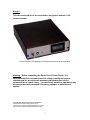
RICHARDSON
PRODUCTS
INCORPORATED
User’s Manual
PowerTech II Power Center
Patented US 6,222,282 B1
1
Danger:
This device should never be connected to any type of medical or life
support system.
PowerTech II Power Center Patented Technology United States Patent No. US 6,222,282 B1
Warning: Before connecting the PowerTech II Power Center, it is
imperative that the consumer know the voltage, polarity and current
requirements for any electronic accessory equipment that is to be
connected to the Power Center. Your electronic accessory equipment may
become permanently damaged if the wrong voltages or polarities are
applied.
Copyright 2007 Richardson Products Incorporated.
9408 Gulf Stream Road Frankfort, Illinois 60423
Internet Address: WWW.RICHARDSONPRODUCTS.COM
Email Address: [email protected]
2
Introduction
Congratulations on your purchase of the PowerTech II Power Center. This
product is manufactured from the highest quality electronic components
available. If you have purchased any of the option packages available for The
PowerTech II Power Center, please refer to their instruction manuals for further
assistance. This product is designed to provide safe reliable DC voltages to
electronic accessory equipment such as compact disc players, laptop computers,
radios, voice synthesis equipment, etc.
Before beginning the installation process please be sure you have received all of
the components. Identify all of the components and associated hardware that
comprise the PowerTech II Power Center. Becoming familiar with the associated
components will aid in installing the Power Center. Remember to carefully follow
the installation instructions in this manual.
The Power Center ships with the following components:
1 PowerTech II Power Center
1 PowerTech II Power Center RPI Power Plug
1 set of male quick disconnect crimp terminals
1 PowerTech II Power Center User Manual
1 PowerTech II Bracket Kit
Fuse Replacement
PowerTech II Power Center Fuse Specifications
Digikey Part Number: F122-nd 4amps@250Volt Fast Acting
PowerTech Vent and PowerTech II Battery Cable Fuse Specifications
Digikey Part Number: F955-nd 10amp@250Volt Fast Acting
RPI Part Number: H217010 10amps@250volt Fast Acting
You may order replacement fuses directly from Richardson Products Inc.
or feel free to contact the following distributors and arrange for delivery.
DO NOT SUBSTITUE OTHER MANUFACTURED FUSES.
Vendor Contact Information:
www.digikey.com
www.radioshack.com
Online Fuse Replacement Guide: http://www.richardsonproducts.com/fuses.html
3
WARNING: Critical Mounting Considerations
Many of the people using the Power Center are quadriplegics, paraplegics or
people who experience severe muscle spasms. Because the Power Center can
become quite warm during normal operation, special care must be taken to
ensure the users safety.
AS WITH ANY REGULATING POWER SUPPLY, THE POWER CENTER CAN
GET QUITE WARM UNDER NORMAL OPERATION. UNDER CERTAIN
ELECTRICAL LOADS THE UNIT CAN BECOME AS HOT AS 135 DEGREES
FAHRENHEIT. THE UTMOST CARE SHOULD BE EXERCISED IN
DETERMINING THE PHYSICAL LOCATION OF THE POWER CENTER ON
THE WHEELCHAIR. IT SHOULD BE PHYSICALLY IMPOSSIBLE FOR THE
USER’S BODY TO MAKE PHYSICAL CONTACT WITH ANY PORTION OF
THE POWER CENTER.
The Power Center must be located in an open air environment. NEVER PLACE
THE POWER CENTER INSIDE OF AN ENCLOSED AREA. The Power Center
should be fastened directly to the wheelchair using the factory supplied mounting
bracket.
Configuring the Power Center
There are many different types of power wheelchairs available on the market
today. Most wheelchairs use two separate 12 Volt DC batteries to provide power
for operation. The wheelchair batteries need to be electrically connected in
series to yield a 24 Volt supply voltage for the Power Center. There are two
options to connect the Power Center to your wheelchair.
Summary of Option 1 - (Factory Default)
This option uses the RPI Power Plug that shipped with your Power Center. This
configuration obtains access to the required 24 Volts DC input voltage by simply
inserting the RPI Power Plug into the charge/aux jack of the wheelchair. The RPI
Power Plug will extract the required 24 Volts DC from the wheelchair batteries via
the charge/aux jack.
Summary of Option 2 - (Factory Recommended if your wheel chair supports this option)
Most wheelchairs can be wired directly to allow the Power Center to be
hardwired directly to the wheelchair’s batteries. Please check with your
wheelchair manufacturer to see if your wheelchair will allow the wheelchair
batteries to be wired in series to yield 24 volts. Please note: This option should
4
only be performed by a qualified service technician. You will need to obtain RPI
Item #06071 (PowerTech II Power Jack) in the Richardson Products Catalog.
Option 1 Installation: Factory Default
Simply insert the RPI Power Plug into the battery charger/aux jack on the
wheelchair. Take up all excess slack in the wire and zip cord any excess wire to
the frame of the wheelchair. The Power Center ships standard with this wiring
configuration. This completes installation steps for Option #1.
Option 2 Installation: Factory Recommended
Setup
The Power Center requires 24 Volts DC for proper operation. Most wheelchairs
derive their power from two 12 Volt DC batteries. The wheelchair batteries must
be electrically wired in series to yield the required 24 Volts DC. Manufactures
have already have the batteries wired in series. The technician must determine
where to tap into the 24Volts required for proper operation. Use the following as
a guide to help find the 24 Volts for your wheelchair. If you are having trouble
we have provided a web tutorial to help you. Surf to the following link:
http://www.richardsonproducts.com/batbox%20tutorial.html
1. Carefully remove the wheelchair’s battery cover. Some battery boxes have
pre-cut wire channels which will allow the Power Center’s Battery Connector
wires to neatly come out of the battery box. Other battery boxes may require
the user to have a new hole drilled into the battery case. If you have to drill
a new hole in your wheelchair’s battery case, be sure not to drill into the
wheelchair’s batteries!
2. Locate the PowerTech II Battery Quick Disconnect Kit. Feed the PowerTech
II Battery Quick Disconnect Kit through the holes (or pre-cut wire channel)
located on the battery box. Using a voltmeter determine which set of
battery terminals yields the 24Volts for proper operation. Start by taking
the probes of your voltmeter and begin probing the battery terminals. Take
the negative probe of the voltmeter and place it on the negative terminal of
one of the batteries. Next take the positive probe and touch it to the positive
terminal of the other battery…if you see approximately 24Volts on the
voltmeter, you have guessed correctly. If you do not see a voltage, the
probes are on the wrong battery terminals. Move the probes to the opposite
terminals, begin by placing the negative probe on the other negative terminal.
Place the positive probe on the other positive terminal. You should now see
24 Volts. Do not proceed until you find the 24volt. Remember: Your
voltmeter probes will be on different batteries!
5
3. Finding the proper terminals is the hard part of this installation. Now that you
have determined which terminals, install the Battery Quick Disconnect Kit on
the terminals that yield the 24 volts. OBSERVE POLARITY!!! The Brown
wire goes to the negative terminal of the first battery. The Red wire goes to
the positive terminal on the second battery.
4. Using a voltmeter check to see if there is an approximate voltage of 24Volts
DC at the Output Quick Disconnect End. Double check the voltage and
polarity of the 24Volts DC. Brown= Negative Red=Positive
5. Make sure you have made good electrical connections in step #3, then
replace your wheelchair’s battery box cover. Be sure that you have not
inadvertently crimped or cut the Power Tech II Battery Connector wires when
you replace the battery cover. The battery cover should go back on as easily
as it came off. Take up all excess slack in the wire and zip cord any excess
wire to the frame of the wheelchair. This completes installation steps for
option #2.
Power Center Testing
(Note: Option1 or Option2 installation should be completed before proceeding.)
Do not connect any of your accessory devices at this time. Connect the Power
Center’s quick disconnect plug. To turn on the Power Center, flip the power
switch located on the front panel to the up position. You should see the Green
Mode LED light up when the power switch is on. If this does not occur please
check all setup procedures of this manual. Do not proceed until you have
successfully completed this test.
6
Power Center Operation
The Power Center has a built-in Microprocessor that monitors a variety of
electrical signals. The microprocessor has been programmed to monitor for the
event of a short circuit. If the output leads are shorted together, the Power
Center instantly responds by shutting the power off to the accessory device and
then changing the green light to red and emitting a solid continuous tone. If you
ever see a red light displayed or hear the unit beep continuously, a short circuit
has occurred. Power is automatically shut off during a short circuit event, but the
beeper will remain on continuously until the switch on the front of the unit is
physically turned to the off position. Check all wiring to find what has caused the
short circuit. After you have resolved the short circuit issue you may reapply
power to the unit and the green light should display.
The built-in microprocessor also monitors the temperature of the Power Center.
As your accessory device uses power, the Power Center temperature increases.
The Power Center is factory programmed to turn itself off if too much power is
drawn or if the unit gets too hot. Under heavy load conditions the Power Center
will try and provide power to your accessory device for as long as it possible
before the temperature protection electronics require it to shut itself off. There
are 3 built-in temperature warning stages before thermal shutdown occurs. The
Power Center will beep once when the first stage threshold is reached, the unit
will continue to beep until the temperature is decreased. As temperature
increases and the second warning stage is reached, the unit will emit 2 beeps
and continue to beep until the temperature is lowered. When third and final
warning stage is reached the unit will emit 3 beeps and continue to beep until the
temperature is decreased. The Power Center will try and continue to provide
power to your accessory device within the 3 warning stages. However, thermal
shutdown will occur if the temperature goes beyond the 3rd warning stage. The
Power Center turns itself off in thermal shutdown mode. Thermal shutdown is
indicated by a flashing red light and a continuous beep tone. The Power Center
must be manually reset by turning power off using the switch located on the front
panel.
Please note: If the Power Center always ends up in thermal shutdown mode, the
accessory device you are trying to power requires more current than the Power
Center can deliver. Please contact technical support at
www.richardsonproducts.com.
7
Wiring Electronic Accessories
The wires or power accessory cables that provide regulated power to electronic
accessory equipment must have the proper current ratings. The qualified
technician installing the Power Center should always double check the wiring
requirements, voltage ratings, current ratings and the polarity requirements of
any electronic accessory device that is to be connected to the Power Center.
Power Center Output
Given a 24 volt input, the Power Center is capable of supplying voltages from 5
volts to 22 volts. (If lower voltages are required please contact your dealer.) The
Power Center can supply a maximum current up to 5 amps according to the
current and voltage curves posted at www.richardsonproducts.com.
Changing the voltage output of the Power Center is easily accomplished.
Carefully, insert a small flat blade screwdriver into the hole located on the front
panel of the Power Center. As you turn the screwdriver, voltage may be adjusted
up or down. Read the voltage displayed using the digital LCD display located on
the front panel of the Power Center. Adjust the output voltage of the Power
Center to match the voltage required by your accessory device.
VERY IMPORTANT
Adjust to the proper operating voltage before connecting it to your
electronic accessory equipment to be operated. Damage to your electronic
accessory equipment may occur if this precaution is not taken. Remember
to double check the voltage output and check for proper polarity.
8
Connecting Electronic Accessory Equipment
Example:
The user would like to install a laptop computer on board his/her wheelchair. The power
requirements for the laptop computer are 16 Volts DC @ 2.5 amps. Polarity requirements: The
laptop’s plug tip requires a Positive (+) terminal. The laptop’s plug outer case requires a
Negative (-) terminal.
Adjusting Voltage
Simply insert a small flat blade screwdriver into the hole located on the front panel of the Power
Center and adjust until the desired voltage is obtained. For this example, you would turn the dial
until 16 Volts appears on the LCD display. Important: MAKE ALL VOLTAGE ADJUSTMENTS
BEFORE CONNECTING THE POWER CENTER TO THE ELECTRONIC ACCESSORY
DEVICE! DAMAGE TO YOUR ELECTRONIC DEVICE MAY OCCUR IF THIS PRECAUTION IS
NOT TAKEN!
Selecting and Installing an Accessory Power Cable
You may contact Richardson Products to order the specific laptop accessory power cable. This
cable will plug into the universal connector shipped with your Power Center.
Voltage/Polarity Testing
Double check the output voltage and its polarity at the end of the Accessory Cable before
connecting your electronic accessory equipment. In our example, the laptop computer plug
should have a voltage of +16 Volts. The laptop’s plug tip should be of positive (+) polarity and is
outer casing should be of negative (-) polarity.
Connecting your Electronic Accessory Equipment
Double check the voltage and polarity requirements of the electronic accessory power cable with
a voltmeter, and plug in your electronic accessory equipment. Turn on the Power Center via the
Power Switch located on the back panel of the unit. Finally, turn on the electronic accessory
equipment as you normally would.
9
Disclaimer
Richardson Products Incorporated shall not be held liable or assume any
responsibility for damage that may occur to the PowerTech II Power Center or
the electronic accessory equipment intended to be powered from the PowerTech
II Power Center. Therefore it is imperative for the qualified service technician to
be sure of the proper power requirements for the electronic device being
connected to the PowerTech II Power Center. If proper care is taken, the
PowerTech II Power Center will provide a clean, stable power source for properly
connected electronic accessory equipment.
10
RICHARDSON
PRODUCTS
INCORPORATED.
Copyright 2007 Richardson Products Incorporated.
9408 Gulf Stream Road Frankfort, Illinois 60423
Internet Address: WWW.RICHARDSONPRODUCTS.COM
Email Address: [email protected]
©2007 Richardson Products Incorporated.
Power Tech-II Power Center Patented Technology United States Patent No. US 6,222,282 B1
11