1
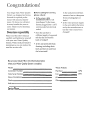
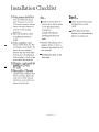
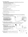
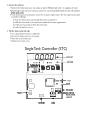
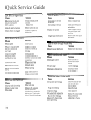
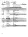
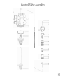
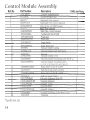
User's Manual
Single Tank Water Quality System
Congratulations!
Your Single Tank Water Quality
System was designed and manufactured for optimal performance with minimal maintenance. We know you will enjoy
its many benefits for years to
come. Thank you for choosing
our system.
Ownerluser responsibility
Please read this User's Manual
carefully and familiarize yourself
with your new Water Quality
System. With a little preventative
maintenance, you can reduce the
need for service calls.
Before calling for service,
please check:
Is the unit protected from
excessive heat or dampness
from sweating pipes or
leaks?
= Is the power cable
connected to the 12 volt
transformer? Is the transformer plugged into a 120V,
continuously hot electrical
outlet?
= Is the water pressure supply
to the unit within the limits
set by the manufacturer or
has the water source been
changed?
= Does the unit have a
sufficient supply of approved
salt that has not become
hard or bridged?
Is the unit protected from
freezing, including drain
lines and lines to and from
the brine-tank?
Be sure your dealer fills in t h e information below
when your Water Quality System is installed.
Model
Water Analysis
Controller Number
Hardness
GPG
Valve Serial Number
lron
PPM
Date of Installation
PH
Dealer
Other
Address
Service Phone
Installation Checklist
O Water pressure should be at
least 20 pounds per square
inch. If pressure is over 80
PSI, install a pressure reducer.
(Most hot water heaters are
rated at 75 PSI working
pressure.)
C1 Flow rate should be at.least
4.5 gallons per minute at
20 PSI
Cl Drain availability-floor
-
.
-.
drain, washer drain, etc. Run
overhead no more than 5 feet
above the water softener.
Increase the size of the drain
for long runs. All plumbing
codes require a 3-inch air gap
at the end of the drain line.
C1 Electricity~ontinuouslyhot
. .
. .. . .
receptacle of 120 volts,
60 cycles.
Ll Water quality-If
the water
supply contains sulphur, iron,
bacteria, tannins, algae, oils,
acids, salt or other unusual
substances, your system may
require pretreatment.
Don't ...
Install the system after the
pressure tank. Ask for advice
on any special plumbing
arrangement.
Comply with all local
plumbing and electrical
codes.
= Examine inlet piping. If it is
clogged, replace or clean it.
Minimum size should be 314
inch nominal.
Install gravity drain on the
brine tank.
= Don't install if inlet water
temperature exceeds
120°F.
Don't allow heat from
torches to be transferred t o
plastic o r valve parts.
Softener Installation
(Single Tank System)
1. Select location for water softener.
Place as close as possible to pressure tank (well water) or water meter (city water).
Place as close as possible to floor drain, laundry drain or sump.
Attach softener to the main water pipe before the water heater.
Bypass outside water faucets to conserve soft water and salt.
= Place softener where it will not freeze.
A 120V electrical outlet must be near. If softener is to be placed outside, care must be taken to
protect all electrical wires, transformer and the electronics.
Softener should be protected from direct sunlight.
= Floor surface must be smooth and level.
2. Open boxes to verify that there is no damage from shipping and all parts are included.
Demand System
Hood with wiring and controller
Turbine with quest nut
12 V (Black) transformer
Black knob - stud (in plastic bag attached
to control valve)
Time System
Includes everything listed under
Demand System except the
turbine and quest nut
3. Provide an in house bypass valve (3a) or
optional brass bypass valve. (3b)
soh
Warer
Service
To
I
I
!
1
.
! i
,
,
ji
I /
i
I
DRAIN
Hard
I Water
INLET
OUTLET
,
Softener
u
Inlet
4. Attach the noryl adapter (or optional brass bypass valve) to the backof the control valve using
the black in and out nipples to make the connection.
Use a small amount of silicone grease on nipple O-rings to prevent damage. (4) Secure with the
connector bars and pan head screws (a). Use clevis in top holes. (b)
5. Connect the softener
A. ELECTRONIC DEMAND SYSTEM
Remove the sensor cable from the turbine.
Spread the clips on each side on the turbine
housing and pull sensor out.
Remove small turbine O-ring around the
mouth of the sensor cavity.
Remove the impeller assembly from the
turbine housing. (Replace later)
Attach the turbine to the lower 1" opening
of the adapter using a 1" PVC coupling (5a, 5b, or 5c).
Leave the sensor cavity in a horizontal position for easy
access and to prevent water from collecting in the hole.
Connect the turbine to the soft water line of the 3 valve
bypass. Use the quest nut or optional 1" nut with
4" copper tail pipe to provide a union for access to the turbine.
Plumb the main hard water line from the 3 valve
bypass into the top 1" (inlet) opening on the adapter.
B. ELECTRONIC TIME SYSTEM
= Since there is no turbine to install, plumb the main hard
water line into the top 1" opening of the adapter.
Plumb the soft water line into the bottom 1" opening of the adapter.
6. Install Drain Line
= Install a 518" ID flexible tube for drain using a 112" barb fitting (not included).
Increase size of drain if it will run overhead or for a long distance.
7. Install the brine tank.
Remove the safety float,from the brine ~7ell.
= Check the valve fittings.
= Remove the rubberband from the bottom of the float and return float to the brine well.
Attach the 318" clear plastic tube from the control valve to the upper elbow that protrudes from
the side of the brine tank.
An overflow drain is located about half way up the side of the brine tank.
Connect's 112" plastic tube to the overflow drain elbow and run to a floor drain or sump.
8. Flush cuttings and other debris from the lines.
A. FOR A 3 VALVE BYPASS
Open a nearby cold water faucet.
Bypass the system by closing the inlet and outlet valves. Open the center bypass valve.
Open the main water shut off valve, to flush the lines.
= Place the bypass in service. Close the center bypass valve. Open the outlet valve. Slowly open the
inlet valve pausing several times to allow air to escape and pressurize the softener slowly.
= Close the water faucet.
B. FOR A BRASS BYPASS
Place the bypass valve into the bypass position by pulling the bypass rod up until it stops.
Turn the knob 114 turn to lock it into place.
Open a nearby cold water faucet.
Open the main water shut off valve to flush the lines.
Close the main water shut off valve
Push the bypass rod all the wa)7 down to put it into the service position.
Close the water faucet.
= Open the main shut off valve to pressurize the system.
Check for leaks.
9. Replace impeller assembly in turbine.
Close main water shut off valve.
Open a nearby faucet to relieve pressure.
Loosen the Quest nut on the turbine and reinstall the impeller assembly.
Retighten the Quest nut.
Close faucet and reopen main water shut off valve.
10. Check the system for leaks.
11. Install controller hood.
Remove stud from plastic bag attached to the control valve and screw it into the tapped hole in
the center of the top lid of the control valve.
Attach the solenoid harness to the control valve. ( I
Connect the red and white cable
to the top solenoid coil.(a)
Connect the green and white cable
to the middle solenoid coil. (b)
Connect the black and white cable
to the bottom solenoid coil. (c)
13. Complete installation of controller hood.
Place the hood over the top of the control valve and all0~7the stud in the top lid to come
through the small hole in the top of the hood. Secure the hood with the black knob.
14. Replace the turbine sensor. (14)
= Replace the turbine O-ring around the opening
of the sensor cavity.
a The proper position for the sensor is identified by
a square projection on the clip and a corresponding
female depression on the turbine housing.
Slip the sensor into the cavity.
Press gently until both sides of the clip have
snapped into place.
15. Attach power cable to the outside two connections of the 12 volt
transformer. ( 15)
Plug transformer into a continuously hot 120V electrical outlet.
cs
5
Softener Start Up
Remove the acrylic door from the front of the controller hood.
1. Program the STC (single tank controller)
STEP 1. SET THE CLOCK
Press the scroll button. A red light will appear next to "Set Clock''.
Press the up or down button under change valve to set the proper 24 hour time. The speed
increases with the length of time button is depressed.
STEP 2. SET REGENERATION TIME
Press scroll. The red light will move to "Set Regeneration Time''.
Press the up or down button to set the proper 24 hour (military time) regeneration time.
STEP 3. SET REGENERATION INTERVAL
Press scroll. The red light will move to "Set Regeneration Interval in Days".
Press the up or down button to set proper regeneration interval. (1-7 days).
Leave setting on auto for demand regeneration. When the system is demand and is set for time
regeneration, it will regenerate on the basis of both time and demand.
STEP 4. SELECT TANK SIZE
Press scroll. The red light will move to "Select Tank Size''.
Press the up or down button to select the proper tank size.
STEP 5. SELECT PULSE OR NON PULSE
Press scroll. The red light will move to "Select Pulse or Non Pulse''.
Press up or down button to select yes for pulse or no for non pulse.
STEP 6. SET COMPENSATED HARDNESS
See chart on page 9 to calculate compensated harness before proceeding. Press scroll. The red
light will move to "Set Compensated Hardness".
Press up or down button to set the proper compensated hardness.
STEP 7. RETURN TO SERVICE
Press scroll to return system to service.
During service, a demand system will display gallons remaining before regeneration and time of
day alternately every 5 seconds. A time system will display total gallons between regeneration and
time of day.
2. Sanitize the softener
= Remove the brine tank cover. Use a hose or pail to fill brine tank with 3 or 4 gallons of water.
Remove the brine well cover and pour about 113 cup of household bleach into the well. Replace
brine well cover.
Press the manual activate button on the STC to start a regeneration. The first regeneration does
a number of things:
It draws the bleach into and through the system to sanitize it.
It refills the brine tank to the water level needed for the next regeneration.
It purges any remaining air from the resin tank.
It settles the bed for service.
3. Fill the brine tank with salt.
Use a good brand of solar o r pellet salt.
= Be sure the brine well cover is in place.
Place salt in the brine tank.
Replace brine tank cover.
Single Tank Controller (STC)
I T 17I T 1-1
Ll,Lh Ll,Ll
II
SET CLOCK
SET REGEN. TIME
1
0
-
II
CHANGE VALUE
I
,
KEYPAD
MANUAL
ACTIVATE
,
PULSE
COMPENSATED
HARDNESS
++
TURBINE
SCROLL
REGENERATION
INTERVAL IN DAYS
DISPLAY
II
0
TEST
0
CHIP
aa
ee.4
POWER
1-1
A
A
TURBINE
A
7
TANK
4 DRIVERS
SOLENOID
INDICATOR
LIGHTS
Additional Features For
Service Technicians
1. Manual activate -- MANUAL REGENERATION
Press manual activate button to start a regeneration.
To stop regeneration continue to press the manual activate button to step the system through all
regeneration cycles back to service.
2. JP2 Prong -- TURBINE COUNTER
Important: Disconnect the turbine cable before using this feature.
Connect the prongs and maintain the connection.
The system will count gallons down to 0 to determine whether the controller will initiate a
regeneration on its own.
3. JP3 Prong -- TEST FEATURE
Connect the JP3 prongs to activate the test feature. Test will appear on the display. Each
solenoid can be enerzized individualy or in combination of two.
Press the up button to energize the number 1 solenoid. (Brine draw)
Press the down button to energize the number 2 solenoid. (Back wash)
Press the manual activate button to energize the number 3 solenoid. (Down flow purge and
brine tank refill)
Press the appropriate button a second time to de-energize the solenoids.
Press scroll to return to service.
SOLENOID INDICATOR LIGHTS
From left to right
First light represents the #1 (Top) solenoid (Brine draw)
= Second light represents the #2 (Middle) solenoid (Back wash)
= Third light represents the #3 (Bottom) solenoid (Purge and brine tank refill).
NOTE: Both the number 1 and number 2 solenoids must be activated to put the system into
back wash. The number one solenoid valve must be open during back wash to provide an
opening for the back wash water from the number two solenoid valve to exit the control valve.
IMPORTANT: Always turn #1 solenoid off first - wait at least 10 seconds then turn off #2 solenoid.
=The controller will return to service if it is left in the programming stage for more than
5 minutes.
= The controller may not proceed to 0 gallons before the system regenerates.
5. TURBINE INDICATOR LIGHT
Red light flashes when meter turns indicating water use.
Programming the Controller
Calculating
compensated hardness
Compensated
hardness factors
1. Enter grains per gallon
of hardness here.
Result
from step 3
2. Enter PPM of iron here.
+
3. Add lines 1 and 2 and
enter result here.
4. Enter the appropriate
compensation factor
from chart at right here.
x
5. Multiply the sum from
line 3 by the
compensation factor
on line 4. Enter result
here.
EXAMPLE
10
Grains
+ 3 PPM Iron
= 13
Total Hardness
x 1.1 Compensation Factor for 13 gr H 2 0
= 14.3 Compensated Hardness
Compensation
factor
Quick Service Guide
Loss o f water pressure
Unit fails t o regenerate
Cause
Solution
Cause
Solution
Electrical service to unit
has been interrupted
Assure constant power
source
Iron buildup in the lines
to the unit
Clean or replace lines
STC is defective
Replace STC
Iron buildup in the unit
Solenoid coils burned out
Replace solenoid coils
Clean unit with acid or
salt additive
Thaw out, replace or
clean drain
Trash in the system
Drain is frozen or plugged
Clean complete control
valve and bypass. Add
pre-filter.
Clogged upper distributor
Remove and clean upper
distributor.
Unit delivers hard water
Cause
Solution
Bypass open
Close bypass
Loss o f resin through house lines
Bypass O-ring damaged
Replace 0-ring(s)
Cause
Solution
No salt or salt is hard
or bridged
Add salt or break up
bridging
Defective lower distributor
Replace lower distributor
Aspirator plugged
Clean aspirator
Insufficient water
refilling brine tank
Check i i 3 solenoid coil,
refill flow control and tank
size setting
Cracked riser tube
Replace riser tube
Back pressure on drain
Correct drain
Broken vacuum breaker
spring
Replace spring
$2 solenoid inoperative
Clean solenoid valve
Replace solenoid coil
- ---
Iron in conditioned water
Cause
Solution
Salt dosage too low
Reset controller or
increase size of flow
control
No salt usage
Correct bridging
Oxidized or colloidal iron
Install post-filter
( 1 or 2 micron)
Excessive water in brine tank
Unit uses t o o much salt
Cause
Solution
Improper tank size setting
Reset tank size
Excessive water in the
brine tank
Defective $1 solenoid.
Trash in the brine
suction line or under the
brine elbow. Trash under
the a3 solenoid diaphragm.
Cause
Solution
#3 solenoid valve leaking
Clean $3 solenoid valve
and check for bent
solenoid guide
Purge check leaking
Check for trash
Aspirator plugged
Clean aspirator
# l solenoid coil inoperative
Replace ftl solenoid coil
Blue dot elbow leaking
back to B.T.when unit is
not regenerating.
Replace elbow or
rubber ball - if worn.
Quick Service Guide, continued
Vacuum breaker leaks
U n i t fails t o draw brine
Cause
Solution
Cause
Solution
Draii~line pluggedifrozen
Clean drain line
Clean o r replace
Aspirator plugged
Clean aspirator
Foreign matter in lip
of vacuum breaker
split ball check.
# I solenoid coil inoperative
Replace # 1 solenoid coil
Low water pressure
Correct pressure
Trash in the purge check
Clean purge check
Bline tube disconnected
Replace or tighten
brine rube
$2 solenoid coil inoperative
Clean or replace
solenoid coil
Odor
Cause
Solution
Anode rod
Remove rod
Sulfur of methane
Consult dealer
Other organics water
conditions changed
Other equipment
may be needed
W a t e r runs t o drain continuously
Salty water after regeneration
Cause
Solution
Trash under +'l or #3
solenoid diaphragm
Clean or replace solenoid
diaphragms
Cause
Solution
Low water pressure
Increase water pressure
Bent solenoid guide
Replace solenoid guide
#2 solenoid coil inoperative
Check power or replace
Broken solenoid spring
Replace solenoid spring
Cage O-ring broken
or missing
Replace cage O-ring
Too much water
in brine tank
Check brine refil! for
continuous flow
Cracked top lid
Replace top lid
Test water for chlorides
or nitrates
Add R.O. for drinking
or find a new source of
Piston return spring
caught
Replace or realign piston
return spring
supply
Brine tank does n o t refill
Cause
Solution
+'3 solenoid coil inoperative
Repiace solenoid coil
Refill flow control plugged
Clean or replace flow control
Driver o n STC inoperative
Replace STC
$1 solenoid valve not
Remove trash from under
diaphragm. Check for
swelling - replace
seating out
Air leak in brine
tubing harness
Replace o r tighten
fittings that leak
Control Valve Assembly
Ref. No.
Description
1
AllNC4182"
Control valve body (brass or noryl)
1
2
A1 CM24VCB4:
Control module assy, complete
1
3
13SCR612SS
Upper distributor mounting screw
2
4
140RING235
Valve base O-ring #235
1
5
6
7
11CKSTEMGUIDE
Check stem guide
1
140NNG121
Riser tube O-ring #I21
1
16UDSS6
Braswell upper distributor
1
8
54T 1050FT
Riser tube
1
9
54LD 15SEG
Braswell lower distributor
1
10
36NUTKB 1032
Black knob
1
Stud
13SCR103212SS
-
13
14
--
15
'/;I
X 1 18-8 SS
Top lid mounting screw
'/3z
-
Units per Assy.
Part Number
X
'/I
6
PL RH MS 18-8 SS
llTOPLID
140RING142
TODlid
Top lid O-ring # 142
1
15PISTONSPG
Piston return spring
1
-
-
1
-
11PISTONCAGE
Piston cage
17
140RING127
Cage O-ring # 127
3
18
AllASPIRATORx
Aspirator
1
19
140RING010
Aspirator O-ring #010
Piston cup seal
2
1
llPISTON
Piston
1
14PISTONGASK
Piston gasket
2
14STEMCKSEAL
Stem check seal
1
11STEMCK
Stem check
1
22
24
?Specify tank size
Control Valve Assembly
Control Module Assemblv
Part Number
Description
1
A11CMBDY
Control modular body
1
2
14CMSEAL
Control module seal
1
3
14BWFC"
Backwash flow control
1
Ref. No.
Units per Assy.
~
4
11BWFCSUP
Backwash flow control support
1
5
1lBDRKEEPER
Brine draw and refill keeper
2
-
Refill flow control
7
11RFCRETAIN
Refill flow control retainer
8
14516CKBALL
5/16
9
10
11PURGEGATE
Purge gate
1
15BRRING1458
Brass ring
2
11
llPURGECK
Purge check
1
12
14PURGESEAL
Purge check seal
13
15VBSPG
Vacuum breaker spring
1
14
14VBBALLCK
Vacuum breaker split ball check
1
14B
15FELTPD
Felt ad
15
11VBCOVER
Vacuum breaker cover
1
16
13SCR838SS
Vacuum breaker mounting screw #8 X '/16
2
17
13SCR142034SS
Control module mounting screw
6
18
1538BRELB18MP
Brass elbow '1s OD X
1
19
llINSSTOP
Ball check stop insert (outlet)
1
20
1538BRELB18MP
Brass elbow 3/s OD X
1
21
llINSSEAT
Ball seat insert (inlet)
1
12SOLDIPHRAG
Solenoid diaphragm high lift
3
23
12SOLARMATURE
Solenoid armature
3
24
12SOLSPRING
Solenoid spring
3
25
12SOLGUIDE
Solenoid guide
3
26
12SOLRETAINER
Solenoid retainer
3
27
13SCR838SS
Solenoid mounting screw #8 X '/16 SS
9
28
12SOL24P
Solenoid
"Specify tank size
diameter check balls
2
.-
'/a
'/8
MPT
MPT
Control Module Assembly
Limited Residential Warrantv
This warranty is extended to the
original owner only and is not
transferable so subsequent owners
of this equipment.
To place the equipment under
warranty, THE WARRANTY REGISTRATION CARD MUST BE
COMPLETED IN ITS ENTIRETY
AND RETURNED TO 415 E.
WASHINGTON ST., Jackson,
Missouri 63755, within thirty (30)
days of installation by a factoryauthorized dealer.
Limitations
Your equipment must be sold by an
authorized dealer in order to receive
benefits of this warranty.
This warranty does not cover
damage due to:
- abuse, misuse or neglect
excessive water pressure
(over 125 PSI)
excessive water temperature
(over 120°F)
Terms
freezing
The manufacturer warrants its
equipment to be free of defects of
workmanship and materials for the
following terms.
alterations
Defective parts wiU be repaired or
replaced FOB Factory when received
from the original owner along with
the serial number.
application or installation not in
accordance with
factory specifications or the
instructions provided in the
users manual or not conforming
to local codes
over-chlorinated water (over 1I!.
ppm residual)
5 Years: From date of manufacture
of valve bodies. The brine tank and
mineral tank if not exposed to direct
sunlight.
5 Years: From date of manufacture
of all, electronic controls, control
valve solenoids, gaskets, springs and
seals.
any other act of God not
reasonably within the dealer's
or manufacturer's power to
prevent or control.
This warranty does not cover labor
or service call costs incurred with
respect to the removal or replacement of any defective part or parts.
Bacterial iron, algae, sand or other
unusual substances present in the
water to be processed must be
removed before entering this
product.
There are no other warranties,
expressed or implied, other than
stated in this document to the extent
permitted by local and state laws.
The manufacturer, shall not be liable
for indirect, special or consequential
damages in connection with the use
of this equipment to the extent
allowed by local state laws.