1
Communications
Driver ActiveX
MODBUS
Users Manual
Version 1.012 --- March 4, 1998
Copyright © 1988 - 1999, Automation Consulting Services, Inc. All rights reserved.
Subject to change without notice.
Table of Contents
SOFTWARE LICENSE.................................................................................................... 1
INTRODUCTION ............................................................................................................. 3
BUILDING MODBUS DRIVER APPLICATIONS ...................................................... 4
Driver Control registration .......................................................................................... 4
Adding the Control to your project ................................................................................ 4
Adding an instance of the Control................................................................................. 4
Setting Properties......................................................................................................... 5
Sending MODBUS commands ........................................................................................ 5
Additional Capabilities ................................................................................................ 6
CABLING .......................................................................................................................... 7
The Cable.................................................................................................................... 7
PC Serial Port ............................................................................................................. 7
AT Serial Port ............................................................................................................. 8
HARDWARE LOCK ........................................................................................................ 9
Hardware Lock............................................................................................................ 9
ERROR CODES.............................................................................................................. 10
EXCEPTIONS ................................................................................................................. 11
SLAVE / AUTOPARSE FRAME EXAMPLE ............................................................. 12
VARIANTS ...................................................................................................................... 14
USER FRAME EXAMPLE............................................................................................ 15
PROPERTIES ................................................................................................................. 18
Understanding Properties............................................................................................. 18
Property Summary........................................................................................................ 18
Serial Port Parameters ............................................................................................... 18
Timeouts ................................................................................................................... 19
Communications Tracing........................................................................................... 19
User Frames and Asynchronous Operation .................................................................. 19
Other Properties......................................................................................................... 19
AsyncButton Property .................................................................................................. 19
AsyncHandshake Property ........................................................................................... 21
AsyncMessage Property................................................................................................ 21
AutoParse Property ...................................................................................................... 22
AutoParse parameter table ........................................................................................... 25
Baud Rate Property ...................................................................................................... 27
Char Timeout Property ................................................................................................ 27
Comm Port Property.................................................................................................... 28
Frame Timeout Property.............................................................................................. 28
i
I/O Mapping Property ................................................................................................. 29
Key Port Property ......................................................................................................... 29
Last Error Property ...................................................................................................... 29
Last Error String Property ........................................................................................... 30
Parity Property.............................................................................................................. 30
Stop Bits Property ........................................................................................................ 30
Trace Enable Property.................................................................................................. 31
Trace File Property....................................................................................................... 31
METHODS....................................................................................................................... 32
Understanding Methods............................................................................................... 32
Conversion Functions ................................................................................................ 32
Diagnostics ................................................................................................................ 32
Receiving and Interpreting Commands ...................................................................... 33
Reading Values.......................................................................................................... 33
Sending User Commands ........................................................................................... 33
Writing Values .......................................................................................................... 33
Optional arguments in C.............................................................................................. 33
Array To Word Method .............................................................................................. 34
Fetch Event Counter Method...................................................................................... 34
Fetch Event Log Method............................................................................................. 34
Force Coil Method....................................................................................................... 35
Force Multiple Coils Method ...................................................................................... 35
Loopback Method ........................................................................................................ 36
Read Exception Status Method.................................................................................... 36
Read General Reference Method................................................................................. 36
Read Input Registers Method ...................................................................................... 37
Read Input Status Method........................................................................................... 37
Read Output Registers Method ................................................................................... 38
Read Output Status Method ........................................................................................ 38
Receive Method............................................................................................................ 39
Receive method Technical Note................................................................................... 39
ReceiveAutoParse Method........................................................................................... 40
Receive Get Byte Method ............................................................................................ 42
Receive Get Integer Method........................................................................................ 43
Release Comm Port Method........................................................................................ 43
Report Slave ID Method.............................................................................................. 43
Trace String Method.................................................................................................... 44
User Add Byte Method ................................................................................................ 44
User Add Integer Method............................................................................................ 45
User Init Method.......................................................................................................... 46
User Send Method ....................................................................................................... 46
UserSendAutoParse Method........................................................................................ 47
Word To Array Method .............................................................................................. 48
Write General Reference Method................................................................................ 48
Write Multiple Registers Method................................................................................ 49
Write Register Method ................................................................................................ 49
ii
MODBUS
Driver ActiveX Control
Software License
IMPORTANT! The enclosed materials are provided to you on the express condition that you agree
to this Software License. By opening the diskette envelope or using any of the enclosed diskette(s)
you agree to the following provisions. If you do not agree with these license provisions, return these
materials to Automation Consulting Services, Inc., in original packaging with seals unbroken, within
3 days from receipt, for a refund.
1. This software and the diskette on which it is contained (the Licensed Software), is licensed to
you, the end user, for your own internal use. You do not obtain title to the Licensed Software or
any copyrights or proprietary rights in the Licensed Software. You may not transfer, sub-license,
rent, lease, convey, copy, modify, translate, convert to another programming language,
decompile, or disassemble the Licensed Software for any purpose.
2. The Licensed Software is provided as-is. All warranties and representations of any kind with
regard to the Licensed Software are hereby disclaimed, including the implied warranties of
merchantability and fitness for a particular purpose. Under no circumstances will the
Manufacturer or Developer of the Licensed Software be liable for any consequential, incidental,
special, or exemplary damages even if apprised of the likelihood of such damages occurring.
Some states do not allow the limitation or exclusion of liability for incidental or consequential
damages, so the above limitation or exclusion may not apply to you.
Incorporated Driver Amendment
If you own OEM Version of the ACS MODBUS driver, this license is amended to provide for the free
or for-profit distribution of software incorporating MODBUS Driver code as follows: you may
distribute executable programs containing the complete and unaltered ACS MODBUS Driver
(Incorporated Version). The Incorporated Version Libraries may not be copied, sold, modified,
distributed, or used by more than one user at a time; they are treated as Licensed Software as
described above. You can only distribute the Driver as a part of self-standing executable code (EXE
files). No royalties or additional licenses are required to distribute such standalone programs.
For Windows DLLs, you may distribute the DLL (distribution) version without royalties, but you
may not distribute the Development (VBX) version. It is treated as Licensed Software as described
above.
For the MODBUS Driver ActiveX control, you may distribute the ActiveX file MBDRVCTL.OCX only
with your applications. The printed documentation and help files are considered Licensed Software
as indicated above. Specifically, you may not sell or otherwise distribute the MODBUS Driver ActiveX
control other than with an application or for use other than as a communications component.
MODBUS
Driver ActiveX Control
MODBUS
Driver ActiveX Control
Introduction
The ACS MODBUS Driver ActiveX Control is a software component that allows application
programs written in a wide variety of languages to communicate with devices that understand the
Gould MODBUS RTU protocol.
The Driver is provided as an ActiveX component (formerly known as OLE Custom Control or
“OCX”). It allows your program to communicate with MODBUS devices by invoking methods and
setting properties. The Driver control handles the MODBUS protocol implementation, variable
conversion, error checking, serial port management, and so on. Information is passed to and from the
control (and hence the MODBUS device) using the host language’s native variable types.
The Driver ActiveX control can be used with any language or development environment that
supports ActiveX controls, including C++, Visual Basic, Delphi, and many others. It supports the
Microsoft Windows 95 and Windows NT operating systems.
The Driver directly implements all the commonly used MODBUS commands. If your application
requires non-standard commands, the control provides methods that allow you to “build” your own
MODBUS command frames and send them. In addition, programs that use the Driver control can act
as MODBUS “master” or “slave” devices, either initiating or accepting commands.
3
MODBUS
Driver ActiveX Control
Building MODBUS Driver Applications
Most applications that use the MODBUS Driver ActiveX control will perform the following steps:
Driver Control registration
Before you can use the Driver ActiveX control, you’ll need to make your programming language
aware of it. This process is called “registration.”
Most languages provide a simple way of adding new ActiveX components to a project. In Visual
Basic 5, for example, you can register the Driver ActiveX control by selecting the “Project /
Components
” command, clicking the “Browse
” button, navigating to the directory where the
Driver control is located, and double-clicking the file MBDRVCTL.OCX. Other languages provide
similar facilities.
You only need to perform this registration step once, the first time you want to use the Driver
ActiveX control. Once the control is registered, it will be available to all applications on the host
system.
Adding the Control to your project
Once the control is registered, you need to add it to your project. Again, the exact procedure will vary
according to the language, but most languages follow a model similar to Visual Basic.
In VB5, you can add the Driver ActiveX control to a project by selecting the “Project /
Components
” command and checking the box next to “MODBUS Driver ActiveX Control.” This
will make the control available on the VB tool palette.
Adding an instance of the Control
To be able to use the Driver, you must add an instance of the Driver ActiveX control to your
program. For languages like Visual Basic, this is as simple as “drawing” a MODBUS control on one of
your application’s forms.
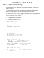
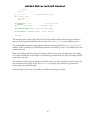
The MODBUS Driver ActiveX control looks like this on the VB tool palette:
Once you’ve drawn a MODBUS control on your VB application’s form, it will look something like
this:
C++ users can create an instance of the control in one of two ways. The simplest way is to draw a
MODBUS control on one of your application’s dialog boxes, much as one would in VB. When you
add the Driver ActiveX control to your C++ project, the development environment will create a
“wrapper” class for it. This class, which will probably be called something like CMBDrvCtrl, allows
you to access the control’s properties and methods using ordinary C++ member functions. So, you
can create an instance of the MODBUS ActiveX control anywhere in your program just by declaring or
allocating a variable of the “wrapper” class.
4
MODBUS
Driver ActiveX Control
Setting Properties
Once the control exists, you can use your development environment’s “object inspector” or propertysheet examiner to set the control’s basic properties, such as communications port, baud rate, and so
on. These “persistent” properties will be saved with the control and hence be “remembered” from
session to session.
If your application will not be changing these properties, it makes sense to set them once and store
them with the control, rather than setting the properties each session under program control.
Sending MODBUS commands
If the communications parameters are set, you are ready to send MODBUS commands. The Driver
ActiveX control has methods for the most commonly-used MODBUS commands. To send a
command, you simply need to invoke the correct method.
For example, let’s suppose that you want to read the current contents of Input Registers 30010
through 30020 from a MODBUS device whose address is 9. Consider the following Visual Basic code
fragment:
Dim status As Integer, V As Variant, n As Integer
status = MB.ReadInputRegisters(9, 30010, 11, V)
If status <> 0 Then
MsgBox "Read Input Registers failed, error: " +
MB.LastErrorString(), _
vbOKOnly Or vbExclamation, "Read Input Registers Test"
Else
For n = 0 to 10
Debug.Print 30010 + n; " = "; V(n)
Next n
End If
Note.
This code assumes that the current form contains a MODBUS Driver control named
“MB.”
The code segment begins by requesting the values of 11 Input Registers starting at 30010 from the
MODBUS device whose address is 9 using the ReadInputRegisters method. When the method
returns, the variable status will contain either 0 for success or an error code.
If the Read Input Registers request fails, status will be nonzero, so the code fragment displays a
message box. The MsgBox statement uses the LastErrorString property to retrieve a text error
message so the user will easily be able to tell what went wrong.
If the request succeeds, the requested register values will be stored in the Variant V as an integer
array. The contents of register 30010 will be in V(0); the contents of 30011 will be in V(1); and so
on. The example simply uses the VB Debug object’s Print method to display the contents of the
11 registers in the Immediate window.
Obviously, a real application would display these values in a more useful way, or otherwise act on the
data values. However, the example should show you the basic procedure used when calling the
MODBUS Driver ActiveX control to send MODBUS commands.
5
MODBUS
Driver ActiveX Control
Additional Capabilities
Most MODBUS Driver applications will probably find the control’s normal MODBUS command
methods contain all the functionality they need. Should the situation arise, the Driver ActiveX
control provides some specialized features:
•
Incoming command processing. Most MODBUS applications will probably operate as MODBUS
“masters,” that is, they will send command and wait for replies. However, the Driver does
support “slave” operation. If you need to accept commands from MODBUS devices, see the
Receive method section.
•
Non-standard commands. The MODBUS Driver ActiveX control contains a generous subset of
the commands allowed by the MODBUS protocol. If you find that the Driver does not provide a
dedicated method for a MODBUS command that you need to send, you can employ the User
command frame methods to build and send unsupported commands.
6
MODBUS
Driver ActiveX Control
Cabling
Normally, your ACS software will be supplied with a cable suitable for connecting the IBM PC or
compatible to the MODBUS device.
However, some of our customers find that they need to make their own cables. This section
describes the cable and pinouts at each end of the connection. The serial port pinouts are included
for reference, since they are not often described in computer manuals.
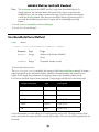
The Cable
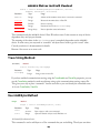
You can use the Driver with a three-wire (Transmit Data, Receive Data, and Ground) cable. ACS
uses the following cable:
Conductor
Signal
IBM PC Pin
IBM AT Pin
Device Pin
1
Ground
7
5
7
3
TD
2
3
3
4
RD
3
2
2
Unfortunately, not all MODBUS devices have standard serial ports. You may need to experiment in
order to find the correct cabling setup. A “breakout box” or similar device can be very helpful while
trying to set up a serial communications link.
PC Serial Port
The IBM PC serial port is a DB25M (25-pin Male) connector. Here are its pinouts (pins not listed
are No Connection):
Pin
Direction
Signal
1
Shield Ground
2
Output
Transmit Data
3
Input
Receive Data
4
Output
Request to Send
5
Input
Clear to Send
6
Input
Data Set Ready
7
Signal
Ground
8
Input
Carrier Detect
9
Output +
Transmit Current Loop
11
Output -
Transmit Current Loop
18
Input +
Receive Current Loop
20
Output
Data Terminal Ready
22
Input
Ring Indicator
25
Input -
Receive Current Loop
Note. Only strictly IBM-compatible serial ports implement the 20ma current loop interface.
7
MODBUS
Driver ActiveX Control
AT Serial Port
The IBM PC AT serial port is a DB9M (9-pin Male) connector. Here are its pinouts:
Pin
Direction
Signal
1
Input
Carrier Detect
2
Input
Receive Data
3
Output
Transmit Data
4
Output
Data Terminal Ready
5
Ground
6
Input
Data Set Ready
7
Output
Request to Send
8
Input
Clear to Send
9
Input
Ring Indicator
8
MODBUS
Driver ActiveX Control
Hardware Lock
Unfortunately, software piracy is a problem that plagues all program developers: the temptation to
copy an unprotected disk is great, and there is little actual danger to the pirate. But copy protection
often offends users and sometimes involves unnecessary “hassles”. In order to keep everyone honest
(with a minimum of trouble for the user) ACS has decided to issue all of its single-user Driver
products in copy-protected form.
Note.
OEM versions of the Driver ActiveX control are not copy protected.
Hardware Lock
A Hardware Lock protects the single-user Driver. Programs protected with a Hardware Lock come
on ordinary floppy diskettes. You can (and should) make backup copies of the protected files, using
the DOS diskcopycommand if you wish. The protection is incorporated into the files themselves
and into the locking device.
The Hardware Lock itself is a small device resembling a “gender changer.” It has two 25-pin
connectors on it, one male and one female.
When you run a program protected with a Hardware Lock, the software will periodically examine
your computer’s parallel printer port. If the correct Hardware Lock is found, the program runs
normally. If the locking device is not present, the program will not operate.
To use the Hardware Lock, simply copy the original program diskettes into a directory on your hard
disk. Next, plug the male end of the Hardware Lock device into your computer’s parallel printer
port (LPT1). If there is a printer already attached to your system, simply plug its cable into the
female end of the Hardware Lock.
Once you have attached the locking device, you are ready to run the software. Your computer should
operate just as before; the device is only active when the software specifically queries it. The Lock is
also transparent to printing.
By default, the Driver looks for the Hardware Key on printer port LPT1. To change the port where
the key is found, use the KeyPort property.
If you are using the default port, LPT1, there is no need to set the KeyPort property. The Driver will
return an error code of -4 if the key is not detected.
9
MODBUS
Driver ActiveX Control
Error Codes
The MODBUS Driver ActiveX control reports errors in two different ways, by using numeric error
codes and by throwing exceptions. Error codes are used to report communications problems, while
exceptions are reserved for more severe conditions that may indicate faults in your application code.
For example, if you send a MODBUS command, and no reply is received, the Driver will report a
Timeout error. However, if you attempt to tell the Driver to send a command to an illegal MODBUS
address, or if you supply a parameter (such as a register address) with an invalid value, the control will
throw an exception.
Error codes are also used to indicate problems reported by the MODBUS device. For example, most
MODBUS devices implement only a subset of the available commands. If you use a Driver method to
send a command that the device doesn’t support, it will return an error code.
Here are the currently defined error codes:
Error
Code
Constant
No error
0
mbdError_None
Hardware Key not found
-4
mbdError_NoKey
Receive Operation Failed
-3
mbdError_NoRecv
Could not send frame
-2
mbdError_NoSend
Timeout
-1
mbdError_Timeout
Bad frame received
1
mbdError_BadFrame
CRC error
2
mbdError_CRC
Returned Frame check failed
3
mbdError_RetCheck
MODBUS
01: Illegal Function
101
mbdError_MB_Func
MODBUS
02: Illegal Data Address
102
mbdError_MB_Addr
MODBUS
03: Illegal Data Value
103
mbdError_MB_Data
MODBUS
04: Failure in Associated Device
104
mbdError_MB_Fail
MODBUS
05: Acknowledge
105
mbdError_MB_Ack
MODBUS
06: Busy, Rejected Message
106
mbdError_MB_Busy
MODBUS
07: NAK
107
mbdError_MB_NAK
MODBUS
08: Memory Parity Error
108
mbdError_MB_Parity
MODBUS errors
are handled by adding 100 to the value returned in the error frame from the MODBUS
device. As a consequence, if you encounter an error greater than 108, subtract 100 from the number
to obtain the MODBUS error identification number.
Such error numbers are not defined in the protocol specification, so you will need to consult your
device’s documentation to determine their meaning.
10
MODBUS
Driver ActiveX Control
Exceptions
The OLE specification provides a way for an embedded control (like the Driver ActiveX control) to
signal serious error conditions to its host. To signal such an error condition, the control can “throw
an exception.”
The MODBUS Driver ActiveX control uses exceptions for serious error conditions, either internal
errors or problems that indicate faults in your application code. For example, if your code tells the
Driver to send a command to an illegal MODBUS address, or if you supply a parameter (such as a
register address) with an invalid value, the control will throw an exception.
The exception mechanism is very different from the numerical error codes used to signal
communications problems. An exception causes the currently executing method to abort immediately
and send a special signal to the host (“container”). How the host reacts to this signal depends on the
programming language.
By default, most languages and development environments will stop your application and display an
error box when an exception occurs. Depending on your programming language’s features, you may
be able to prevent or alter this behavior.
C++, for example, provides the try … catch construct to handle exceptions. By enclosing a
Driver call in a try block, you can intercept and handle any exceptions that may occur.
Visual Basic provides exception handling via the on error goto statement. When an exception
occurs after an on error goto statement, control flows to the statement named in the on
error command. Your code can then determine what action to take and resume normal execution.
It should be stressed that you normally shouldn’t need to worry about the exception mechanism.
Once your code is debugged, the Driver control should never need to throw an exception. If an
exception does occur in debugged code, the situation is probably very serious.
During debugging, exceptions are actually very valuable. By stopping the program and signaling a
serious error, the Driver is telling you that there is probably a bug in your code. This makes finding
errors much quicker.
“Routine” communications errors (such as Timeouts and CRC errors) do not cause the Driver to
throw exceptions. Instead, these problems are reported via the error code returned by each method.
Your code needs to check for and handle these errors, obviously, but you probably don’t need to
worry about exception handling for most applications.
11
MODBUS
Driver ActiveX Control
Slave / AutoParse Frame Example
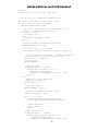
This example shows how one might process incoming MODBUS commands. The code acts as a
MODBUS slave device.
For the purposes of this example, this code responds only to Read Output Status commands
addressed to MODBUS address 17. All other commands and addresses are ignored.
The example returns a simple bit pattern regardless of the address requested. In a real application,
you would obviously want to use the starting register address to determine what data gets sent.
This code assumes that the form contains:
•
A MODBUS ActiveX control called MB.
•
A hidden button called RTHidden.
Private Sub Form_Load()
'
' Start the serial port watcher by setting the AsyncButton property
' to the invisible button's window handle
'
MB.AsyncButton = RTHidden.hWnd
End Sub
Private Sub RTHidden_Click()
'
' Read commands
'
Dim rc As Integer
Dim addr As Integer, cmd As Integer
Dim startCoil As Long, ct As Integer
Dim hp As Integer
rc = MB.ReceiveAutoParse(addr, cmd)
If addr <> 17 Or cmd <> 1 Then
Exit Sub
' Not a command we care about
MB.AsyncButton = RTHidden.hWnd ' Reset watcher
End If
startCoil = MB.AutoParse(0)
ct = MB.AutoParse(1)
' Read starting coil number
' Read count
hp = ct / 16
' Make array for bit values
ReDim bits(hp + 1) As Integer
For n = 0 To hp
If n And 1 Then
bits(n) = &HC0C0
Else
bits(n) = &H505
' Set up simple bit pattern
12
MODBUS
Driver ActiveX Control
End If
Next n
hp = ct / 8
If ct And 7 Then
hp = hp + 1
End If
MB.AutoParse(0) = hp
MB.AutoParse(1) = bits
' Calculate byte count
' Set byte count
' Set data array
MB.UserSendAutoParse addr, cmd ' Send the reply
MB.AsyncButton = RTHidden.hWnd
' Reset watcher
End Sub
The example code is quite simple. The forms Load method initializes the serial port watcher so
that any incoming command frame will cause the RTHidden_Click event handler to start.
The event handler begins by retrieving the incoming command with the ReceiveAutoParse
method. If the command is not Read Output Status or the address is not 17, the handler resets the
watcher and exits.
Next, the handler reads the starting coil number and coil count. In a real application, the starting
coil number should have some effect on the data being returned with the reply; the example always
returns the same data.
The handler creates an array of pattern data of the correct size, then calculates the byte count (the
first parameter in the reply). It sets the AutoParse property array elements to generate the
correct reply, then sends the reply.
Once the reply is on its way, the handler re-enables the serial port watcher.
13
MODBUS
Driver ActiveX Control
Variants
The MODBUS Driver ActiveX control makes extensive use of the OLE Variant data type. The major
reason for this is that there is no other standard way to safely pass arrays between the host application
and the control.
Variants can contain virtually any kind of data, including arrays. Since a Variant containing an array
provides information about the dimensions of the array, the control can avoid reading or writing
“past the end” of the array. This prevents a class of severe and irretrievable crashes (Illegal Page
Faults).
The Variant data type is not as familiar to programmers as more common types, such as strings and
integers. However, it is very versatile and well suited to passing data to and from the Driver ActiveX
control.
OLE provides standard ways to change the type of a Variant, to detect “empty” Variants, and so on.
For example, if you pass an “empty” Variant to the Driver’s ReadInputRegisters method, the control
will automatically “fill” the Variant with an integer array containing the register values you’ve
requested.
Visual Basic supports the Variant type directly; simply Dim a variable As Variant. MFC includes
the COleVariant class, which is a simple wrapper of a Variant.
If your programming language supports ActiveX controls (OCXes), it must provide support for the
Variant data type. You should consult your language’s documentation for more information.
14
MODBUS
Driver ActiveX Control
User Frame Example
This example is intended to demonstrate two of the MODBUS Driver ActiveX control’s more
advanced capabilities, incoming command processing and user command frames.
Note.
You do not need to use the Receive or User commands to issue and receive standard
MODBUS commands. Use the dedicated methods for this.
For this example, let’s assume that we need to write an application that will let a PC pass
information to a large plant-wide control system, such as a Honeywell TDC 3000. The PC will act
as an operator terminal that allows plant personnel to change recipe variables for a process.
The PC will maintain a set of recipe variables that can be altered by the program’s operator; the
TDC will retrieve these values and use them to operate the process it controls.
Rather than trying to write the recipes into the controller, we’ve decided to let the TDC poll the PC
for recipe values at its own convenience. This makes the operator terminal program look like any
other device under the TDC’s control.
To do this, we’ll need to accept requests for recipe values from the TDC and send back properly
formatted replies. Further, our program should only accept and reply to commands it “understands”
that have been sent to its assigned address.
Let’s set some parameters. We’ll say that the PC has the MODBUS address 27, and that the values
the TDC will retrieve are “stored” in registers 34040 through 34060. The TDC will be programmed
to request these registers from the PC at a regular interval and incorporate the values into the process
control logic.
The TDC will use the MODBUS command Read Input Registers (function 4) to retrieve the recipe
values from the PC, so we need to “listen” for this command. The Read Input Registers command is
formatted as follows in the MODBUS protocol specification:
MODBUS
address
1 byte
Function number
1 byte = 4
Starting Register address
1 word
Register count n
1 word
The reply message looks like this:
MODBUS
address
1 byte
Function number
1 byte = 4
Byte count
1 byte
Data values
n words
Here’s the code fragment that will handle the data requests from the TDC:
Dim addr As Integer, cmd As Integer, clen As Integer
Dim stat As Integer, startReg As Long
Dim nregs As Integer, n As Integer, subsc As Integer
While Not cancelFlag
15
MODBUS
Driver ActiveX Control
DoEvents
stat = MB.Receive(addr, cmd, clen, 100)
'
' See if this is a command we should process
'
If stat = 0 And addr = 27 And cmd = 4 Then
' Retrieve the starting address
MB.ReceiveGetInteger addr
' addr is a signed integer, so convert to a long
' VB has no unsigned 16-bit integer...
If addr >= 0 Then
startReg = addr
Else
startReg = &H10000& + addr
End If
' Read the number of registers requested
MB.ReceiveGetInteger nregs
' Is this a legal register range?
If startReg < 34040 Or startReg + nregs > 34060 Then
' No, send back Error Frame 2, Illegal Data Address
' Error frame is function number or 80H
MB.UserInit 27, &H80 Or 4
' Error code 2
MB.UserAddByte 2
' Send the code...
If MB.UserSend() <> 0 Then
MsgBox "Error sending error: " +
MB.LastErrorString(), _
vbOKOnly or vbExclamation, "Data Poll"
End If
Else
' Request is legal, send data
' Begin by setting up
MB.UserInit 27, 4
' Add byte count
MB.UserAddByte nregs * 2
' Figure out offset into value array
subsc = startReg – 34040
For n = 1 To nregs
' Add a value from the master array
MB.UserAddInteger RegisterValues(subsc)
' Next subscript
subsc = subsc + 1
Next n
' Send the values...
If MB.UserSend() <> 0 Then
MsgBox "Error sending values: "
+ MB.LastErrorString(), _
vbOKOnly or vbExclamation, "Data Poll"
16
MODBUS
Driver ActiveX Control
End If
' Legal register range
End If
' Command we should answer
End If
' "Listening" loop
Wend
This example code fragment makes several assumptions:
•
The variable cancelFlag will be set to True elsewhere in the program when the “listening”
loop is to exit.
•
The recipe values are stored in an array called RecipeValues.
•
There is an instance of the MODBUS Driver ActiveX control called MB on the current form.
The code in this example should be fairly easy to understand. Basically, there is a main loop that
waits for incoming commands until the cancelFlag variable becomes True. In order to allow the
application’s user interface to continue to update, the loop waits only 100 milliseconds (1/10 second)
and executes a DoEvents call with every iteration.
If a command is received, the code checks to see if it is addressed to the PC. It also checks to make
sure the command is Read Input Registers (the only MODBUS command we are supporting) and that
the registers requested fall inside the range that we have values for, that is, 34040 to 34060.
Assuming the incoming command passes all these tests, the code constructs an outgoing reply in the
correct format and sends it.
17
MODBUS
Driver ActiveX Control
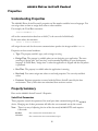
Properties
Understanding Properties
The MODBUS Driver ActiveX controls properties act like member variables in most languages. You
can assign values to them or assign their values to other variables.
For example, the Visual Basic statement:
control.BaudRate = 7
will set the communications baud rate to 9600 (7 is the rate code for 9600 baud).
By the same token, the statement:
intvar = control.BaudRate
will assign the rate code for the current communications speed to the integer variable intvar.
Properties can have several attributes:
•
Type. The property variables type, such as integer or string.
•
Design Time. The property is available when you are designing your application. The exact
meaning of design time and run time varies somewhat depending on your development
language. In Visual Basic, design time is when the application is stopped and the tool palette
is presented.
•
Run Time. The property is available when the application is running.
•
Read-only. You cannot assign new values to read-only properties. You can only read their
values.
•
Persistent. Persistent properties are stored with the Driver ActiveX control by the host
environment. That is, their values are maintained from session to session.
Property Summary
Here are the MODBUS ActiveX control’s Properties:
Serial Port Parameters
These properties control the operation of the serial port when communicating with the MODBUS
device. Changing one of these parameters will affect the next command sent by the control.
Note.
There is no way of adjusting the size of the data word; MODBUS RTU mode requires
8 bit words.
BaudRate
Sets or retrieves the communications rate.
CommPort
Sets or retrieves the current communications port.
18
MODBUS
Driver ActiveX Control
Parity
Sets or retrieves the current Parity setting.
StopBits
Sets or retrieves the Stop Bits setting
Timeouts
The Timeout properties control when the Driver determines that an incoming MODBUS frame has
completed and how long the control will wait for an incoming message to begin.
CharTimeout
Sets or retrieves the character timeout, which tells the Driver when an incoming frame has
been completely received.
FrameTimeout
Sets or retrieves the frame timeout, the length of time the Driver waits for an incoming
message to begin arriving.
MODBUS
Communications Tracing
Communications tracing allows you to track every byte sent or received by the Driver ActiveX
control.
TraceEnable
Turn communications tracing on or off.
TraceFile
Specify the output text file that is to receive the communications tracing information.
User Frames and Asynchronous Operation
AsyncButton
Designates a button to be clicked by the asynchronous notification system when an
incoming frame arrives.
AsyncHandshake
Enables or disables changes in the serial port RTS signal during asynchronous
receiving.
AsyncMessage
Specifies the Windows message used to signal incoming command frames when in
asynchronous mode.
AutoParse
Property array used to interpret incoming frames and construct replies.
Other Properties
IOMapping
Sets or retrieves the I/O Mapping mode.
LastError
Retrieves the last error code encountered by the Driver.
LastErrorString
Translate the last error code (or any error code) to a string.
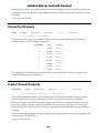
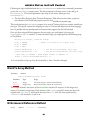
AsyncButton Property
Long Integer
Property
! Design Time
" Run Time
! Read Only
! Persistent
oldHandle = control.AsyncButton
control.AsyncButton = newHandle
Intended for advanced users.
#$
This property allows you to respond asynchronously to incoming commands.
Using the Receive method in the traditional way, your program would have to poll for incoming
19
MODBUS
Driver ActiveX Control
commands. That is, you would have to set up a loop that would call the Receive method repeatedly
until an incoming command was detected.
This is obviously an inefficient approach, especially in a GUI application. In languages like Visual
Basic, the application will become unresponsive if you put the program into a tight loop on the
Receive method. Languages that dont support multithreading can have serious difficulties
handling this sort of situation.
The AsyncButton property is designed to permit your application to invoke the Receive method
only when you know that a command is actually arriving. Until a command is detected, your program
can go about its business.
The AsyncButton property is intended for languages such as Visual Basic and Delphi that have no
inherent support for multithreading and no easy way to accept arbitrary messages from the operating
system.
Technically, AsyncButton sets up a worker thread that watches the serial port. When an incoming
command is detected, this thread sends a message to your application that has the effect of clicking a
button on your programs form. When your application gets this message, its time to invoke the
Receive or ReceiveAutoParse method to accept and reply to an incoming command.
During the interval when no commands are arriving, the MODBUS ActiveX controls watcher thread
consumes no CPU time. Using AsyncButton is a very efficient way to create an application that
operates as a MODBUS slave, especially when coupled with the ReceiveAutoParse and
UserSendAutoParse methods.
To use AsyncButton, begin by creating a button on your applications form, then make the button
invisible. You dont want your users to be able to see the button because only the MODBUS ActiveX
control will click it. In Visual Basic, you make a button invisible by setting its Visible property
to False.
Within your program, when you are ready to start watching for incoming commands, set your
MODBUS ActiveX controls AsyncButton property to the invisible buttons window handle. The
window handle is an arbitrary 32-bit integer that has meaning only to Windows. In Visual Basic, this
handle is exposed via the buttons hWnd property; Delphi uses the Handle property.
As soon as your program sets the AsyncButton property to the buttons window handle, the
MODBUS ActiveX control will begin watching for incoming commands. When an incoming
command is detected, the control will click the invisible button.
Your program will handle incoming commands using code attached to the invisible buttons click
event. Within this code, you might, for example, retrieve the command using the
ReceiveAutoParse method, then transmit a reply using the UserSendAutoParse method.
Note.
The AsyncButton property must be reset after each incoming command
notification. This is to protect your program from having the invisible buttons click
event handler called during processing of a command.
To re-enable the serial port watcher, simply reset the AsyncButton property to the invisible
buttons window handle, just as you did initially.
•
To disable the serial port watcher, set the AsyncButton property to zero.
20
MODBUS
Driver ActiveX Control
#$See also AutoParse Property Array, ReceiveAutoParse, UserSendAutoParse, AsyncMessage,
AsyncHandshake
AsyncHandshake Property
Boolean
Property
" Design Time
" Run Time
! Read Only
" Persistent
control.AsyncHandshake = True (default) or False
Intended for advanced users.
#$
When operating in asynchronous mode, the MODBUS ActiveX control normally provides the signals
needed for hardware handshaking. When an incoming frame has been detected, the control lowers
the RTS signal until your code returns to the asynchronous listening mode.
When used with a device that supports hardware handshaking, this feature permits you to avoid
receiving additional incoming frames while you are processing a frame. The RTS signal tracks your
applications handling of the incoming command: it will be true when you are ready to receive an
incoming frame and false while you are processing a frame.
This type of handshaking will have no effect on MODBUS devices that dont support RTS/CTS
handshaking. In fact, many MODBUS devices are connected using a three-wire (transmit data, receive
data, ground) cable.
However, if you are writing a program that operates as a MODBUS slave, you may find it worthwhile
to investigate hardware handshaking. This will enable you to process commands more reliably,
especially if your application performs extensive processing or screen updates in response to incoming
commands.
If you set the AsyncHandshake property to False, the serial ports RTS signal will always be true.
See also AsyncButton, Slave / AutoParse Example
#$
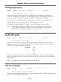
AsyncMessage Property
Long Integer
Property
" Design Time
" Run Time
! Read Only
" Persistent
control.AsyncMessage = Windows Message Number
Intended for advanced users.
#$
This property determines what Windows message the MODBUS Driver ActiveX control sends when
it wishes to notify your application that an incoming command frame has arrived. It applies only
when you have set up asynchronous listening with the AsyncButton property.
By default, the control uses the message WM_COMMAND. It reads the control ID of the button passed
to AsyncButton property and uses that as the command number in the message. This approach
should work for all Microsoft languages.
21
MODBUS
Driver ActiveX Control
You should only need to change this property if you are using a non-Microsoft language that doesnt
interpret WM_COMMAND properly. Unfortunately, Borland Delphi is such a language. It does not obey
this standard Windows message. For Delphi, you should use WM_LBUTTONDOWN.
You could also change this message if you wish to use a private application-specific message that you
have defined. Advanced programmers who use languages like C++ frequently use this technique.
The Driver ActiveX handles messages in the following way:
•
WM_COMMAND. The default message. When this message is set, the ActiveX control reads the
Control ID of the button passed to the AsyncButton property. When an incoming frame is
detected, the Driver ActiveX sends a WM_COMMAND message to the indicated target window
with the command ID equal to the Control ID retrieved previously. Use with Microsoft
languages.
•
WM_LBUTTONDOWN. This setting causes the Driver ActiveX to simulate a mouse click on
the control specified with the AsyncButton property. When an incoming frame is detected,
the Driver sends a WM_LBUTTONDOWN / WM_LBUTTONUP pair to the target control.
Note.
•
The WM_LBUTTONDOWN mode is highly inefficient. In this mode, the Driver
ActiveX must send two messages to your application for each incoming frame.
Also, the WM_LBUTTONDOWN message is transmitted with SendMessage
rather than the more efficient PostMessage. This mode is provided only to
support Borland Delphi users; Delphi is not responsive enough to handle more
traditional methods like the default (posted WM_COMMAND).
Other messages. For all other messages, the Driver ActiveX will simply post the specified
message to the control set using AsyncButton. This approach would typically be used when
your application wishes to use a private user-defined message for incoming frame notification.
See also AsyncButton, Slave / AutoParse Example
#$
AutoParse Property
Integer
Property
! Design Time
" Run Time
! Read Only
! Persistent
oldValue = control.AutoParse(index)
control.AutoParse(index) = newValue
This is a property array is designed to hold several parameters of varying types. The exact meaning of
each parameter depends on the MODBUS command being processed; there is a table below that
describes the parameters in detail.
Assuming oldValue and newValue are both Variants or Variant-compatible types, you can
retrieve or assign values to or from the property array using the syntax above. The index variable is a
16-bit integer that can range from 0 to 4, allowing five parameters in total.
Note that not all MODBUS commands use all five parameters. Many commands need only one or two
parameters.
22
MODBUS
Driver ActiveX Control
Both the ReceiveAutoParse and UserSendAutoParse methods use the AutoParse array.
The ReceiveAutoParse method will decode incoming command frames and put the
information that it finds into elements of the AutoParse property array. The
UserSendAutoParse method uses information from the property array to construct replies to
incoming commands.
The exact use of these commands is demonstrated and explained in the Slave Mode example.
Note.
The IOMapping property affects register addresses in the AutoParse property
array. If IOMapping is True, the MODBUS Driver ActiveX control will
automatically translate register addresses.
23
Driver ActiveX Control
MODBUS
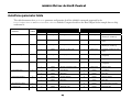
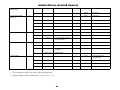
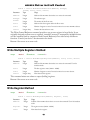
AutoParse parameter table
This table documents the AutoParse parameter configuration for all the MODBUS commands supported by the
ReceiveAutoParse and UserSendAutoParse methods. Compare the table to the Read Output Status example above to help
understand it.
Receiving
Command
Read Output Status
Read Input Status
Read Output Registers
Read Input Registers
Force Single Coil†
Write Single Register†
Number
Element
Type
1
0
Integer
1
2
3
4
5
6
Element
Type
Starting coil number*
0
Integer
Integer
Number of coils to read
1
Integer Array
0
Integer
Starting coil number*
0
Integer
1
Integer
Number of coils to read
1
Integer Array
Coil values, packed into 16-bit
words
0
Integer
Starting register number*
0
Integer
Byte count (twice the number
of registers)
1
Integer
Number of registers to read
1
Integer Array
0
Integer
Starting register number*
0
Integer
1
Integer
Number of registers to read
1
Integer Array
0
Integer
Coil address*
0
Integer
Coil address
1
Integer
New value
1
Integer
New value
0
Integer
Register address*
0
Integer
Register address
1
Integer
New value
1
Integer
New value
-
0
Integer
Exception status coil value
Diagnostic code
0
Integer
Diagnostic data
Read Exception Status
7
-
-
Loopback Test
8
0
Integer
Description
Replying
25
Description
Byte count (number of coils
divided by 8, rounded up)
Coil values, packed into 16-bit
words
Byte count (number of coils
divided by 8, rounded up)
Register values
Byte count (twice the number
of registers)
Register values
Driver ActiveX Control
MODBUS
Fetch Communications
Event Counter
Fetch Communications
Event Log
Force Multiple Coils
Write Multiple Registers
Report Slave ID
11
12
15
16
17
-
-
-
-
-
-
Integer
Status
1
Integer
Event count
0
Integer
Byte count
1
Integer
Status
2
Integer
Event count
3
Integer
Message count
4
Integer Array
Event bytes
0
Integer
Starting coil address*
0
Integer
Starting coil address*
1
Integer
Number of coils to write
1
Integer
Number of coils written
2
Integer Array
0
Integer
Starting register address*
0
Integer
Starting coil address*
1
Integer
Number of registers to write
1
Integer
Number of registers written
2
Integer
Byte count (twice the number
of registers)
3
Integer Array
-
-
0
Integer
Byte count for devicedependent data
1
Integer
Slave ID
2
Integer
Run Light
3
Integer Array
Coil values to write, packed
into 16-bit integers
Register values
-
Notes:
†
0
The commands reply is the same as the incoming frame.
* Register address will be translated if IOMapping is True.
26
Device dependent data
MODBUS
Driver ActiveX Control
Baud Rate Property
Integer
Property
" Design Time
" Run Time
! Read Only
" Persistent
control.BaudRate = Rate Code
Sets or retrieves the current baud rate used for communications with the MODBUS device. The Rate
Code must be one of the integer values below:
Rate Code
Baud Rate
0
110
1
150
2
300
3
600
4
1200
5
2400
6
4800
7
9600
8
19200
9
38400
10
57600
11
115200
Char Timeout Property
Long Integer
Property
" Design Time
" Run Time
! Read Only
" Persistent
control.CharTimeout = Timeout in Milliseconds
The MODBUS protocol has no explicit framing, that is, it does not have codes that indicate when a
message begins or ends. Instead, the protocol relies on time. Specifically, the protocol says that the
end of each message is marked by a “silent” period lasting for at least the length of time required to
transmit two and one half characters at the current baud rate.
The CharTimeout property tells the Driver how long it should wait before determining that an
incoming message is complete. In most cases, the default value of 50 milliseconds should be
adequate.
Note.
This is a 32-bit quantity.
However, if you frequently have problems receiving replies from the MODBUS device, or if you are
communicating at low baud rates, you may need to increase this value.
Note that the CharTimeout value is only used once an incoming message has started to arrive. The
FrameTimeout property determines how long the Driver will wait for an incoming message to begin.
27
MODBUS
Driver ActiveX Control
Reducing the CharTimeout value may provide increased throughput if you are trying to sample at the
maximum possible rate. However, values below 50 milliseconds may cause erratic operation on some
computers.
See also Frame Timeout
#$
Comm Port Property
Integer
Property
" Design Time
" Run Time
! Read Only
" Persistent
control.CommPort = Port Number
Sets or retrieves the current port used for communications with the MODBUS device. The port
number must be one of the integer values below:
Port Number
Port
Constant
0
COM1
mbdCom_1
1
COM2
mbdCom_2
2
COM3
mbdCom_3
3
COM4
mbdCom_4
4
COM5
mbdCom_5
5
COM6
mbdCom_6
6
COM7
mbdCom_7
7
COM8
mbdCom_8
The number of communications ports supported by your system will vary. Many computers don’t
support COM ports beyond number 4.
Frame Timeout Property
Long Integer
Property
" Design Time
" Run Time
! Read Only
" Persistent
control.FrameTimeout = Timeout in Milliseconds
This property determines how long the control waits for an incoming MODBUS message to begin,
either in response to an outgoing command or while “listening” for an incoming command.
When you transmit a MODBUS command using any of the Driver’s command methods, it will wait
for a reply to begin arriving for the time specified by the FrameTimeout property. Once the reply
begins to arrive, the control uses the CharTimeout property to detect when the incoming message is
complete.
If no incoming message begins arriving during the time specified by the FrameTimeout property, the
control returns a Timeout Error.
See also Char Timeout
#$
28
MODBUS
Driver ActiveX Control
I/O Mapping Property
Boolean
Property
" Design Time
" Run Time
! Read Only
" Persistent
control.IOMapping = { True | False }
Normally, the Driver ActiveX control maps the Register and Coil addresses that you pass to
conform to the Protocols specifications. For example, if you refer to Holding Register 40127, the
actual binary address transmitted by the Driver will be 126, as defined by the Protocol.
However, if you are not working with Gould equipment, or if you need to control the actual
transmitted addresses, you can disable address mapping with this command.
I/O Mapping is enabled by default. To disable it, set the IOMapping property to False.
Note.
If you disable I/O Mapping, the Driver ActiveX control will perform no address range
checking. When I/O Mapping is disabled, you are responsible for supplying register
and point addresses exactly as the MODBUS device will receive them.
Key Port Property
Integer
Property
" Design Time
" Run Time
! Read Only
" Persistent
control.KeyPort = Port Number
For copies of the Driver ActiveX control that are protected by a Hardware Lock, this command
changes the printer port that the Driver searches for the hardware key. The default is 0, which selects
LPT1. Use one of the port number codes below:
Port Number
Port
0
LPT1
1
LPT2
2
LPT3
The Driver will periodically check for the presence of the Hardware Lock on the port indicated by
the KeyPort property. If the key is not found, the Driver will return an error code of -4, “Hardware
Key not found.”
Note.
This property is not used for OEM versions of the Driver.
Last Error Property
Integer
Property
! Design Time
" Run Time
! Read Only
! Persistent
IntegerVariable = control.LastError
Retrieves or sets the integer number of the last error reported by the Driver ActiveX control or zero if
no error occurred during the last operation.
29
MODBUS
Driver ActiveX Control
Last Error String Property
Integer
Property
! Design Time
" Run Time
" Read Only
! Persistent
StringVariable = control.LastErrorString()
or
StringVariable = control.LastErrorString(errorNumber)
Retrieves the last error reported by the Driver ActiveX control in string format. If you supply the
optional argument errorNumber, the Driver will return the string equivalent of the specified error
number.
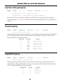
Parity Property
Integer
Property
" Design Time
" Run Time
! Read Only
" Persistent
control.Parity = Parity Code
This property determines whether any parity bits are used during communications with the MODBUS
device. The Parity Code must be one of the values in the table below. The default value of 0 (No
Parity) should be used in most situations.
Parity Code
Port Parity
Constant
0
None
mbdParity_None
1
Odd
mbdParity_Odd
2
Even
mbdParity_Even
3
Mark
mbdParity_Mark
4
Space
mbdParity_Space
Stop Bits Property
Integer
Property
" Design Time
" Run Time
! Read Only
" Persistent
control.StopBits = Stop Bits Code
This property determines the number of stop bits that are used during communications with the
MODBUS device. The Stop Bits Code must be one of the values in the table below. The default value
of 0 (1 stop bit) should be used in most situations.
Stop Bits Code
Stop Bits
Constant
0
1
mbdStops_1
1
1.5
mbdStops_15
2
2
mbdStops_2
30
MODBUS
Driver ActiveX Control
Trace Enable Property
Boolean
Property
! Design Time
" Run Time
! Read Only
! Persistent
control.TraceEnable = { True | False }
This property enables or disables communications tracing, which is disabled by default.
Communications tracing allows you to see all the data that passes through the communications link
in both directions. It can be very useful for diagnosing difficult communications problems.
When communications tracing is enabled, all bytes that are sent and received are recorded to the
ASCII text file specified in the TraceFile property. You can enable and disable tracing repeatedly as
needed during a session. For example, you can set the TraceEnable property to True just before
sending a MODBUS command that isn’t working properly, then set the TraceEnable property back to
False before sending other commands.
Note.
The TraceFile property must be set to a legal filename before communications tracing
will work. Your program must also explicitly set the TraceEnable property to True
before tracing will begin; the TraceEnable property is not stored from session to
session.
Tip.
You can annotate the Trace File contents using the TraceString method.
See also TraceFile Property, TraceString
#$
Trace File Property
String
Property
" Design Time
" Run Time
! Read Only
" Persistent
control.TraceFile = "Legal filename.txt"
The TraceFile property specifies the output file that the Driver ActiveX control will use to save
communications tracing output. Once you have set this file and enabled tracing by setting the
TraceEnable property to True, the Driver will “print” every byte that passes through the
communications port under its control to the specified file.
Once your program exits, you can examine this file to see what exactly was sent and received for every
issued by your program. The file will contain ASCII text in a simple tabular
format.
MODBUS command
Tip.
You can annotate the Trace File contents using the TraceString method.
See also TraceEnable Property, TraceString
#$
31
MODBUS
Driver ActiveX Control
Methods
Understanding Methods
Methods act like subroutines and functions. Invoking a MODBUS Driver ActiveX control method is
very like calling a function within your own application. For example, the Visual Basic statement:
status = control.ReadInputRegisters(14, 30014, 5, v)
sends a Read Input Registers command to the MODBUS device whose address is 14. The command
frame will request 5 registers starting at register 30014. The register values will be stored in the
Variant v, and the error code, if any, will be returned in the variable status.
Methods can have several attributes:
•
Return type. This specifies the type of the value returned by the method. For communications
methods, this is always an integer.
•
Broadcast. Some MODBUS commands allow you to transmit in broadcast mode. This means
that all connected devices will receive and act on the command. Note that the official MODBUS
protocol specifies that only a handful of commands permit broadcast mode.
•
Command number. Methods that transmit MODBUS commands show the decimal command
number that will actually be sent. Some MODBUS devices specify the commands they accept by
number rather than by name.
Note.
In the method descriptions below, variables that will be modified by the MODBUS
Driver ActiveX control appear in underlined type.
Conversion Functions
Convenience functions for manipulating data:
ArrayToWord
Converts an array of 16 integers to a 16-bit word.
WordToArray
Converts a 16-bit word to a 16-element integer array.
Diagnostics
Detecting the state of the MODBUS device and discovering error conditions:
FetchEventCounter
Retrieves the count of successfully executed MODBUS commands.
FetchEventLog
Retrieves a log of information about all MODBUS transactions.
Loopback
Test communications link and/or retrieve diagnostic information.
ReadExceptionStatus
Retrieves the state of the device’s special status coils.
ReportSlaveID
Determines the slave device’s type and run state.
ReleaseCommPort
Terminates the Driver’s control of any serial port it is currently
using.
TraceString
Writes a text annotation to the Communications Tracing file.
32
MODBUS
Driver ActiveX Control
Receiving and Interpreting Commands
Accepting MODBUS commands from a remote device:
Receive
Waits for an incoming MODBUS command frame.
ReceiveAutoParse
Wait for and interpret an incoming MODBUS command frame.
ReceiveGetByte
Extract a byte or bytes from the incoming command.
ReceiveGetInteger
Extract an integer or integers from the incoming command.
Reading Values
Obtaining process data from the MODBUS device:
ReadGeneralReference
Read data from “extended memory” files.
ReadInputRegisters
Retrieve values from one or more input registers.
ReadInputStatus
Read the status of discrete inputs.
ReadOutputRegisters
Read values from one or more output (holding) registers.
ReadOutputStatus
Read the status of discrete outputs (coils).
Sending User Commands
Creating and sending commands not directly supported by the MODBUS Driver ActiveX control:
UserAddByte
Adds a byte or bytes to a User command being constructed.
UserAddInteger
Adds an integer or integers to a User command being constructed.
UserInit
Sets up the Driver ActiveX control for transmission of a user
command.
UserSend
Transmits a user command frame.
UserSendAutoParse
Constructs and transmits a reply to an incoming MODBUS
command.
Writing Values
Transmitting values to registers and points on the MODBUS device:
ForceCoil
Writes a value to a single coil.
ForceMultipleCoils
Writes values to a series of consecutive coils.
WriteGeneralReference
Writes data to “extended memory” files
WriteMultipleRegisters
Writes new values to a series of consecutive registers.
WriteRegister
Writes a new value to a single register.
Optional arguments in C
C, C++, and C-like languages support “optional” OLE parameters only indirectly. You cannot simply
omit an optional parameter and expect the program to work properly.
Technically, optional OLE parameters are passed as const FAR VARIANT &, that is, a reference
to a Variant. You must supply a Variant whether you want to use the parameter or not.
33
MODBUS
Driver ActiveX Control
To indicate that an optional parameter is omitted, you should set the Variant’s type to VT_EMPTY
or VT_ERROR. Officially, Microsoft recommends, “If an optional argument to an Automation
method is left blank, do not pass a VARIANT of type VT_EMPTY. Instead, pass a VARIANT of type
VT_ERROR with a value of DISP_E_PARAMNOTFOUND (0x80020004L).”
Array To Word Method
(no return)
Method
control.ArrayToWord Values, Word
Parameter
Type
Usage
Values
Integer Array
Bit values to combine. Must have at least 16 elements.
Word
Integer
Variable to contain combined bits.
Combines the bits in the input array Values into the single 16-bit integer Word. Element 0 of
Values becomes bit 0 of Word; element 15 of Values becomes bit 15 of Word.
Note.
Any non-zero element of Values will become a 1 in the output word.
Fetch Event Counter Method
Integer
Method
" Broadcast
Command 11
Status = control.FetchEventCounter(Address, Busy, Events)
Parameter
Type
Usage
Address
Integer
Address of the MODBUS device that is to receive the command. Use 0 for broadcast
mode (addressed to all devices).
Busy
Boolean
Flag indicates that a previous command is still being processed.
Events
Integer
Count of MODBUS commands successfully processed by the device.
Retrieves the MODBUS device’s Busy flag and Event counter. You can use the Event counter to tell
when commands have completed successfully. This is a good way to detect when commands that
require substantial processing time have finished.
Returns 0 for success or an error code.
Fetch Event Log Method
Integer
Method
" Broadcast
Command 12
Status = control.FetchEventLog(Address, Busy, EventCt, MsgCt, Log)
Parameter
Type
Usage
Address
Integer
Address of the MODBUS device that is to receive the command. Use 0 for
broadcast mode (addressed to all devices)
34
MODBUS
Driver ActiveX Control
broadcast mode (addressed to all devices).
Busy
Boolean
Flag indicates that a previous command is still being processed.
EventCt
Integer
Count of MODBUS commands successfully processed by the device.
MsgCt
Integer
Number of events in the Event Log.
Log
Integer Array
Contents of the event log, one byte per element.
Retrieves a MODBUS device’s Event Log. Each entry in the log will occupy one element of the Log
array.
The exact meaning of these entries will depend on the device. Usually, but not always, these are bytewide bitmaps.
Returns 0 for success or an error code.
Force Coil Method
Integer
Method
" Broadcast
Command 05
Status = control.ForceCoil(Address, Coil, Value)
Parameter
Type
Usage
Address
Integer
Address of the MODBUS device that is to receive the command. Use 0 for broadcast
mode (addressed to all devices).
Coil
Integer
Address of the coil to force (1 – 9999).
Value
Boolean
Value to apply to coil.
Changes an output to a specific value.
Returns 0 for success or an error code.
Force Multiple Coils Method
Integer
Method
" Broadcast
Command 15
Status = control.ForceMultipleCoils(Address, Start, Count, Values)
Parameter
Type
Usage
Address
Integer
Address of the MODBUS device that is to receive the command. Use 0 for
broadcast mode (addressed to all devices).
Start
Integer
Address of the first coil to force (1 – 9999).
Count
Integer
Number of coils to force.
Values
Integer Array
Values to apply to coils.
Changes a group of outputs to specific values. The new values are supplied to the method packed
into 16-bit words. Bit 0 of Values(0) will supply the value for Start; Bit 1 will set Start + 1,
and so on. Bit 0 of Values(1) will set Start + 16. The ArrayToWord method can be very handy
for building the Values array.
35
MODBUS
Driver ActiveX Control
Returns 0 for success or an error code.
See also ArrayToWord
#$
Loopback Method
Integer
Method
" Broadcast
Command 08
Status = control.Loopback(Address, DiagCode, Info)
Parameter
Type
Usage
Address
Integer
Address of the MODBUS device that is to receive the command. Use 0 for broadcast
mode (addressed to all devices).
DiagCode
Integer
Code indicating diagnostic to run.
Info
Integer
Parameter value for diagnostic.
Runs a diagnostic on the MODBUS device. The DiagCode parameter specifies which diagnostic to
run; the Info parameter may be used by some diagnostic operations and ignored by others. Some
diagnostic functions will return information via the Info parameter.
The specific diagnostics available vary from device to device, but diagnostic 0, the Loopback test, is
always implemented. This test simply sends back the Info value unchanged.
Returns 0 for success or an error code.
Read Exception Status Method
Integer
Method
! Broadcast
Command 07
Status = control.ReadExceptionStatus(Address, Value)
Parameter
Type
Usage
Address
Integer
Address of the MODBUS device that is to receive the command.
Value
Integer
Returns the contents of the Exception register.
Reads the MODBUS device’s Exception register. Depending on the device, this bits in this register
may reflect error or status conditions. On Programmable Logic Controllers, this register is usually
linked to certain specific special coils.
Returns 0 for success or an error code.
Read General Reference Method
Integer
Method
! Broadcast
Command 20
36
MODBUS
Driver ActiveX Control
Status = control.ReadGeneralReference(Address, _
RefType, FileNo, Start, Count, Values)
Parameter
Type
Usage
Address
Integer
Address of the MODBUS device that is to receive the command.
RefType
Integer
The reference type.
FileNo
Integer
The number of the file to read.
Start
Integer
Address of the first register within the file to read.
Count
Integer
Number of registers to read. Limited to 120 or less on most MODBUS devices.
Values
Integer Array
Returns the requested registers.
The Read General Reference command provides a way to retrieve registers in large blocks. It was
originally designed to allow access to optional “extended” memory. Contemporary MODBUS devices
use this command (and its companion, Write General Reference) for a wide variety of different
functions. Consult your device’s documentation for details.
Returns 0 for success or an error code.
Read Input Registers Method
Integer
Method
! Broadcast
Command 04
Status = control.ReadInputRegisters(Address, Start, Count, Values)
Parameter
Type
Usage
Address
Integer
Address of the MODBUS device that is to receive the command.
Start
Integer
The first register to read (30001 – 39999).
Count
Integer
Number of registers to read. Limited to 120 or less on most devices.
Values
Integer Array
Returns the requested registers.
Reads the contents of input registers.
Returns 0 for success or an error code.
For an example, see Sending MODBUS Commands
#$
Read Input Status Method
Integer
Method
! Broadcast
Command 02
Status = control.ReadInputStatus(Address, Start, Count, Values)
Parameter
Type
Usage
Address
Integer
Address of the MODBUS device that is to receive the command.
Start
Integer
The first input to read (10001 – 19999).
Count
Integer
Number of inputs to read. Limited to 2000 or less on most devices.
37
MODBUS
Integer Array
Values
Driver ActiveX Control
Returns the requested inputs.
Reads the status of discrete inputs. The input states are returned packed into 16-bit integers. Bit 0
(the least significant bit) of Values(0) will contain the state of the input designated by Start;
Bit 1 will contain the state of (Start + 1), and so on. You can use the WordToArray method to
break the elements of Values into individual bits if that is more convenient.
Returns 0 for success or an error code.
See also WordToArray
#$
Read Output Registers Method
Integer
Method
! Broadcast
Command 03
Status = control.ReadOutputRegisters(Address, Start, Count, Values)
Parameter
Type
Usage
Address
Integer
Address of the MODBUS device that is to receive the command.
Start
Integer
The first register to read (40001 – 49999).
Count
Integer
Number of registers to read. Limited to 120 or less on most devices.
Values
Integer Array
Returns the requested registers.
This command reads the current contents of output (holding) registers.
Returns 0 for success or an error code.
Read Output Status Method
Integer
Method
! Broadcast
Command 01
Status = control.ReadOutputStatus(Address, Start, Count, Values)
Parameter
Type
Usage
Address
Integer
Address of the MODBUS device that is to receive the command.
Start
Integer
The first output to read (1 – 9999).
Count
Integer
Number of outputs to read. Limited to 2000 or less on most devices.
Values
Integer Array
Returns the requested outputs.
Reads the status of discrete outputs (coils). The output states are returned packed into 16-bit
integers. Bit 0 (the least significant bit) of Values(0) will contain the state of the output
designated by Start; Bit 1 will contain the state of (Start + 1), and so on. You can use the
WordToArray method to break the elements of Values into individual bits if that is more convenient.
Returns 0 for success or an error code.
See also WordToArray
#$
38
MODBUS
Driver ActiveX Control
Receive Method
Integer
Method
Status = control.Receive(Address, Command, Length, Wait)
Parameter
Type
Usage
Address
Integer
Returns the address the incoming command was sent to.
Command
Integer
The MODBUS command number in the incoming message.
Length
Integer
Total length in bytes of the incoming command.
Wait
Long Integer
Optional length of time in milliseconds to wait for an incoming command.
Intended for advanced users.
#$
This method allows your application to receive commands from other MODBUS devices.
Most applications that use the MODBUS driver will act as “masters.” They will send commands to
MODBUS devices using methods like ReadInputStatus that automatically wait for and process the
error and information frame sent back by the “slave” device.
However, you can use the Receive method to cause your application to act as a MODBUS slave. The
Receive method waits for a correctly formatted MODBUS command. If such a command arrives, the
Receive method will return its MODBUS address, command number, and frame length in the variables
listed above. If no MODBUS command arrives within the time allotted, the Receive method will
return a Timeout error.
By default, the Receive method waits for the length of time specified in the FrameTimeout property.
You can choose another wait interval by specifying the optional Wait parameter.
Note.
You do not need to use the Receive method to obtain results from “master” methods
like ReadInputStatus. Use this method only if you want to wait for incoming
commands from another device or retrieve replies from a User command.
Once a command has arrived, you can check the Address and Command variables to see if your
application should process the message. You can use the ReceiveGetByte and ReceiveGetInteger
methods to “break” the incoming message into parameters.
If the application needs to send a reply, it can employ the User methods.
Note.
If the Receive method successfully captures an incoming frame, the “current position”
used by both ReceiveGetByte and ReceiveGetInteger will be set to the first byte of
user data in the frame (just after the MODBUS address and command numbers).
Returns 0 for success or an error code.
Receive method Technical Note
When you call the Receive method, the calling thread will block until a command is received or until
the allotted timeout elapses. This means no CPU time will be used, but it also means that the thread
will not respond to Windows messages. If you use your application’s main thread to call Receive, and
use a long timeout value, the application’s user interface won’t update until the Receive method
exits.
39
MODBUS
Driver ActiveX Control
If your application is going to spend most of its time waiting for incoming commands, you may want
to place the code that calls the Receive method on an alternate thread, leaving your application’s
main thread to handle GUI updates.
If you are using a language like Visual Basic, which doesn’t directly permit multithreading, you may
want to use construct like this:
While control.Receive(Address, Cmd, Length, 100) = mbdError_Timeout
DoEvents
Wend
' Process the incoming command
While this example considerably oversimplifies what would be done in a real application, it gives the
idea. This performs a GUI update (uses the VB DoEvents command to process messages) every
tenth of a second (the Wait value is 100 milliseconds). That will permit the application to be
responsive to the user while continuing to “listen carefully” for incoming MODBUS commands.
A future version of the Driver ActiveX control will support asynchronous notification of incoming
MODBUS commands, but this version supports only polled reception.
See also ReceiveGetByte, ReceiveGetInteger
#$
See also User Frame Example
#$
ReceiveAutoParse Method
Integer
Method
status = control.ReceiveAutoParse(Command, Address, Wait)
Parameter
Type
Usage
Command
Integer
The MODBUS command number in the incoming message.
Address
Integer
Returns the address the incoming command was sent to.
Wait
Long Integer
Optional length of time in milliseconds to wait for an incoming command.
Intended for advanced users.
#$
The ReceiveAutoParse method is an extension of the controls standard Receive method. It
functions in the same general way as the Receive method, except that incoming frames are subject
to additional processing.
The optional WaitTimeout parameter has exactly the same effect as it does on the Receive
method. It tells the control how long to wait for an incoming command frame. If this parameter is
not supplied, the method will wait for length of time specified by the current value of the
FrameTimeout property.
The Command and Address parameters, both 16-bit integers, describe the incoming frame if one
is received. After a successful receive operation, the Command variable will contain the frames
command number, and the Address variable will contain the MODBUS node number that the
command was addressed to.
40
MODBUS
Driver ActiveX Control
As always, the functions return code (assigned to the variable status in this case) will be zero for a
successful operation or an error code otherwise.
If the control successfully receives a MODBUS command during execution of the
ReceiveAutoParse method, it will examine that command. The control has built-in templates
that tell it how to interpret the most popular commands.
These templates tell the control the construction of each MODBUS command. As an example, lets
take the ReadOutputStatus command.
Oversimplifying a bit, at the binary level, a ReadOutputStatus command looks something like
this:
Sample Value (hex)
Type
Description
11
Byte
Destination address
01
Byte
Function code
0013
Word
Starting coil number
0025
Word
Number of coils to read
If this command were received by the ReceiveAutoParse method, the command parameter
would be set to 1 for Read Output Status, and the address parameter would be set to 17 (11 hex).
From this information, your application will know how to process the command. For example, if
your application has the address 17 decimal, you might process the command; otherwise, you might
ignore it. Once you decide to process the command, the function code 1 tells you that the remote
device sent the Read Output Status command. This would presumably tell your program what kind
of data to include in the reply.
To create a reply, your program will need to know what coils the remote device is requesting, and
how many. To get this information, youll use the AutoParse property array.
The ReceiveAutoParse method uses its templates to examine incoming commands. The
template tells the method the number of parameters included in the command and the type of each
parameter. In our example (the Read Output Status command), there are two parameters: the
starting coil number, and the number of coils to read.
The ReceiveAutoParse method assigns each parameter in the incoming command frame to a
member of the AutoParse property array. In this case, AutoParse(0) would get the value 19
(13 Hex), which is the starting coil number. AutoParse(1) would get the value 37 (25 Hex), the
number of coils to read.
ReceiveAutoParse works the same way with all the commands that it has templates for: each
parameter in the incoming command is assigned to a successive element of the AutoParse property
array. This means that you can interpret any supported incoming command just by reading the
command number (which will tell you how to act on what you get) and by accessing elements of the
AutoParse property array.
•
The AutoParse Received Parameters table shows what information appears in each member of
the AutoParse property array for each MODBUS command.
41
MODBUS
Driver ActiveX Control
Obviously, youll need to send a reply to the incoming command. To do that, youll use the
UserSendAutoParse method.
See also AutoParse Property Array, Slave / AutoParse Example, UserSend Auto Parse Method
#$
Receive Get Byte Method
(no return)
Method
control.ReceiveGetByte Value, Count, Position
Parameter
Type
Usage
Value
Integer
Returns byte(s) from the incoming message.
Count
Integer
Optional. The number of bytes to retrieve. Defaults to 1.
Position
Integer
Optional. Offset from the beginning of the frame. Defaults to the current position.
Intended for advanced users.
#$
Retrieves one or more bytes from an incoming MODBUS message captured by the Receive method.
Note. You must use the Receive method to capture an incoming command frame before using the
ReceiveGetByte method. If you call this method with no received frame in memory, the Driver
ActiveX control will throw an exception.
The ReceiveGetByte method (and its companion ReceiveGetInteger) allows you to step through a
received MODBUS command frame one parameter at a time. By default, if you supply neither a
Count nor a Position argument, the ReceiveGetByte method retrieves a single byte from the
“current” position and advances the “current” position by one byte.
The “current position” used by both ReceiveGetByte and ReceiveGetInteger starts at the first byte
of user data in the frame (just after the MODBUS address and command numbers).
If you supply a Count value greater than 1, Value will be returned as an integer array with one byte
from the incoming command in each element. Value(0) will contain the byte at the “current”
position, Value(1) the next byte, and so on, until Count bytes have been copied. When the
method returns, the “current” position will be increased by Count.
If you want to retrieve bytes from a position other than the “current” position maintained by the
Driver, you can supply a Position argument. If you supply this argument, the Driver ActiveX
control will begin retrieving bytes at the specified position. When the method returns, the “current”
position will point just after the last byte retrieved.
Normally, you will probably want to step through the incoming frame in order, breaking out bytes
and integers as needed to understand the command. However, you can override this “stepping”
process by supplying a Position argument.
Note. If you supply a Count or Position that would cause the control to try to retrieve data from
before the beginning of the frame or after its end, the control will throw an exception.
See also Receive, ReceiveGetInteger
#$
See also User Frame Example
#$
42
MODBUS
Driver ActiveX Control
Receive Get Integer Method
(no return)
Method
control.ReceiveGetInteger Value, Count, Position
Parameter
Type
Usage
Value
Integer
Returns integer(s) from the incoming message.
Count
Integer
Optional. The number of integers to retrieve. Defaults to 1.
Position
Integer
Optional. Offset in bytes from the beginning of the received frame. Defaults to the
current position.
Intended for advanced users.
#$
Operates in exactly the same way as ReceiveGetByte, except (obviously) it extracts integers instead of
bytes.
Note.
This method returns a signed integer. If you are extracting an unsigned integer value,
you will need to perform the necessary conversion (usually to a long integer).
See also Receive, ReceiveGetByte
#$
See also User Frame Example
#$
Release Comm Port Method
(no return)
Method
control.ReleaseCommPort
The first time that you invoke a Driver method that requires the use of the serial port, the MODBUS
Driver ActiveX control will automatically connect to the port and stay connected. The Driver will
normally maintain control of the serial port until the host application ends.
If you need to release the serial port (perhaps so another application can use it) you can invoke the
ReleaseCommPort method. This method causes the Driver to immediately terminate its connection
to the serial port and free the port.
Note.
If you change the port that the Driver is using (via the CommPort property), it will
automatically release any connection it is currently maintaining and open the new
port on the next method invocation that requires serial port access.
Report Slave ID Method
Integer
Method
! Broadcast
Command 17
43
MODBUS
Driver ActiveX Control
Status = control.ReadOutputRegisters(Address, SlaveID,
RunMode, DDataCount, DeviceData)
Parameter
Type
Usage
Address
Integer
Address of the MODBUS device that is to receive the command.
SlaveID
Integer
Returns the MODBUS device’s Slave ID.
RunMode
Boolean
Device is running.
DdataCount
Integer
Number of items in the DeviceData array.
DeviceData
Integer Array
Device-dependent status information.
This command reads the MODBUS device’s Slave ID and run state. It also returns an array of devicedependent data, one byte per element.
The meaning of the values in the DeviceData array is completely dependent on the MODBUS
device. In some cases, you may need to “assemble” two bytes into a word to get the “actual” value.
Consult your device’s documentation for details.
Returns 0 for success or an error code.
Trace String Method
(no return)
Method
control.TraceString "StringExp"
Parameter
Type
Usage
StringExp
Integer
String to write to trace file.
If you have enabled communications tracing using the TraceEnable and TraceFile properties, you can
use the TraceString method to send any arbitrary string to the communications tracing output file.
This gives you a way to place “comments” into the trace file so you can identify the command traces.
See also TraceEnable, TraceFile
#$
User Add Byte Method
Integer
Method
length = control.UserAddByte(Value, Count)
Parameter
Type
Usage
Value
See below
Byte or bytes to add to user command.
Count
Integer
Optional. Number of bytes to add. Defaults to 1.
Intended for advanced users.
#$
This command is used to add bytes to a User command that you are building. These bytes are taken
44
MODBUS
Driver ActiveX Control
from the Value parameter, which is a Variant. Since Variant parameters can contain a wide variety of
data types, the actual type used here depends on your application. You can pass a single byte, a single
integer, a byte array, or an integer array.
The Count parameter determines how the Value parameter is interpreted. If Count is 1 or
omitted, the Driver will treat Value as a scalar, adding its Least Significant Byte to the frame. If
Value is an array, the Driver will add the Least Significant Byte of Value(0) to the user
command frame.
If Count is greater than 1, then Value must be an array of integers or bytes. The Driver ActiveX
control will add the Least Significant Byte of Count elements of the array to the user command
frame.
Returns the new length of the outgoing command frame.
Note.
You must set up the User command frame with the UserInit method before you can
use the UserAddByte method. If you call the UserAddByte method before UserInit,
the control will throw an exception.
See also UserAddInteger, UserInit, and UserSend.
#$
See also User Frame Example
#$
User Add Integer Method
Integer
Method
length = control.UserAddInteger(Value, Count)
Parameter
Type
Usage
Value
See below
Integer or integers to add to user command.
Count
Integer
Optional. Number of integers to add. Defaults to 1.
Intended for advanced users.
#$
Works in exactly the same way as the UserAddByte method, but adds integers (words). For this
method, the Value parameter can contain only a single integer or an integer array.
Returns the new length of the outgoing command frame.
Note.
You must set up the User command frame with the UserInit method before you can
use the UserAddInteger method. If you call the UserAddInteger method before
UserInit, the control will throw an exception.
See also UserAddByte, UserInit, and UserSend.
#$
See also User Frame Example
#$
45
MODBUS
Driver ActiveX Control
User Init Method
(no return)
Method
length = control.UserInit(Address, Command)
Parameter
Type
Usage
Address
Integer
The address to receive the MODBUS command. Use 0 for broadcast mode.
Command
Integer
The MODBUS command number (0 – 255).
Intended for advanced users.
#$
The UserInit method sets up the MODBUS Driver ActiveX control for the construction and
transmission of a user command frame. You must call this method before you can call any of the
other user command methods, such as UserAddByte, UserAddInteger, and UserSend.
The user command methods allow you to construct MODBUS commands that are not natively
supported by the Driver. You may need to use this method if your device requires nonstandard
commands, or if you need to reply to an incoming MODBUS command captured with the Receive
method.
Calling the UserInit method establishes what MODBUS command you want to send and what address
you want to send the command to. After calling UserInit, you can use the UserAddByte and
UserAddInteger methods to append data to the end of the command frame, if any additional data is
needed. Once the frame is complete, use the UserSend command to transmit it.
Note.
The user command methods are needed only to transmit MODBUS commands not
already supported by the driver. You do not need to call the User methods to use
MODBUS protocol commands like Read Input Status. Such commands have their own
dedicated methods (e.g., ReadInputStatus).
See also UserAddByte, UserAddInteger, and UserSend.
#$
See also User Frame Example
#$
User Send Method
Integer
Method
Status = control.UserSend()
Intended for advanced users.
#$
Sends a user command frame that has been built with the UserInit, UserAddByte, and
UserAddInteger commands.
Returns 0 for success or an error code.
Note.
You must set up the User command frame with the UserInit method before you can
use the UserSend method. If you call the UserSend method before UserInit, the
control will throw an exception.
46
MODBUS
Note.
Driver ActiveX Control
The UserSend method does NOT wait for a reply from the MODBUS device. It
simply transmits the command frame and returns. If you expect a reply from the
MODBUS device, and you want to examine this reply, you must capture and interpret
it with the Receive method. Note that you can simply choose to ignore any reply if
you wish; the MODBUS protocol doesn’t require you to acknowledge incoming
frames.
See also UserInit, UserAddByte, and UserAddInteger
#$
See also User Frame Example
#$
UserSendAutoParse Method
Integer
Method
length = control.UserSendAutoParse(Address, Command)
Parameter
Type
Usage
Address
Integer
Address of destination MODBUS
device
Command
Integer
Command number to send
Intended for advanced users.
#$
The UserSendAutoParse method is the converse of the ReceiveAutoParse method. It creates a
reply frame based on the destination address, MODBUS command number, and parameters you
supply. Youll supply these parameters by assigning values to the AutoParse property array.
Lets look at the Read Output Status command. A reply might look like this at the binary level:
Sample Value (hex)
Type
Description
11
Byte
Destination address
01
Byte
Function code
05
Byte
Byte count
CD6B
Word
Coils 20-35
B20E
Word
Coils 36-51
1B
Byte
Coils 52-56
As youll remember, we were asking for 37 coils beginning with coil 20. The reply contains a byte
count, which tells the remote device how much data to expect. The coil values follow packed into 16bit words.
47
MODBUS
Driver ActiveX Control
Following the logic established with the ReceiveAutoParse method, the commands parameters
go into the AutoParse property array. The first parameter is the byte count, so that will go in
AutoParse(0). The second parameter is the array of coil values, which goes into
AutoParse(1).
•
The AutoParse Property Array Transmit Parameters Table tells you what values to place in
each element of the AutoParse property array for each MODBUS command reply.
This works because the AutoParse property is an array of Variants, which can contain virtually any
data type. The specific method for assigning an array to a Variant will depend on the host language,
but it is possible with any development environment that supports the ActiveX standard.
Once you have assigned all the parameters for your reply, you can dispatch it by using the
UserSendAutoParse method. To create the above reply, you might perform the following steps
in Visual Basic:
Dim bv(3) As Integer, status As Integer
bv(0) = &HCD6B
bv(1) = &HB20E
bv(2) = &H1B
' Assign coil values to an integer array
control.AutoParse(0) = 5
control.AutoParse(1) = bv
' Set the first parameter, byte count
' Set the second parameter, the value array
' Send reply to command 1 (Read Output Status) to address 17
status = control.UserSendAutoParse(17, 1)
See also AutoParse Property Array, ReceiveAutoParse, Slave / AutoParse Example
#$
Word To Array Method
(no return)
Method
control.WordToArray Word, Values
Parameter
Type
Usage
Word
Integer
The 16-bit integer to break into individual bits.
Values
Integer Array
Returns the bits that make up the source word.
This simple method is the reverse of the ArrayToWord method. It accepts a 16-bit integer and
returns a 16-element integer array. Each element of the Values array will contain one bit of the
original word. Values(0) will contain the state of Word’s bit 0 (the least significant bit),
Values(1) will contain bit 1, and so on.
Write General Reference Method
Integer
Method
! Broadcast
Command 21
48
MODBUS
Driver ActiveX Control
Status = control.WriteGeneralReference(Address, RefType,
FileNo, Start, Count, Values)
Parameter
Type
Usage
Address
Integer
Address of the MODBUS device that is to receive the command.
RefType
Integer
The reference type.
FileNo
Integer
The number of the file to write.
Start
Integer
Address of the first register within the file to write.
Count
Integer
Number of registers to write. Limited to 120 or less on most MODBUS devices.
Values
Integer Array
Contains the data values to write.
The Write General Reference command provides a way to store registers in large blocks. It was
originally designed to allow access to optional “extended” memory. Contemporary MODBUS devices
use this command (and its companion, Read General Reference) for a wide variety of different
functions. Consult your device’s documentation for details.
Returns 0 for success or an error code.
Write Multiple Registers Method
Integer
Method
" Broadcast
Command 16
Status = control.WriteMultipleRegisters(Address, Start, Count, Values)
Parameter
Type
Usage
Address
Integer
Address of the MODBUS device that is to receive the command. Use 0 for
broadcast mode.
Start
Integer
The first register to write (40001 – 49999).
Count
Integer
Number of registers to write. Limited to 120 or less on most devices.
Values
Integer Array
New values for the registers.
This command writes new values to output (holding) registers.
Returns 0 for success or an error code.
Write Register Method
Integer
Method
" Broadcast
Command 06
Status = control.WriteRegisters(Address, Register, Value)
Parameter
Type
Usage
Address
Integer
Address of the MODBUS device that is to receive the command. Use 0 for broadcast
mode.
Register
Integer
The register to write (40001 – 49999).
Value
Integer
New values for the register.
49
MODBUS
Driver ActiveX Control
This command writes a new value to a single output (holding) register.
Returns 0 for success or an error code.
50
MODBUS
Driver ActiveX Control
Index
A
AutoParse parameter table ................................................................................................ 25
B
Building MODBUS Driver Applications............................................................................... 4
C
Cabling ................................................................................................................................ 7
E
Error Codes ....................................................................................................................... 10
Exceptions ......................................................................................................................... 11
H
Hardware Lock.................................................................................................................... 9
I
Introduction......................................................................................................................... 3
M
Methods
Array to Word................................................................................................................ 34
Fetch Event Counter ..................................................................................................... 34
Fetch Event Log ............................................................................................................ 34
Force Coil....................................................................................................................... 35
Force Multiple Coils ...................................................................................................... 35
Loopback........................................................................................................................ 36
Read Exception Status ................................................................................................... 36
Read General Reference................................................................................................. 36
Read Input Registers...................................................................................................... 37
Read Input Status........................................................................................................... 37
Read Output Registers................................................................................................... 38
Read Output Status........................................................................................................ 38
Receive ........................................................................................................................... 39
Receive Get Byte............................................................................................................ 42
Receive Get Integer ....................................................................................................... 43
ReceiveAutoParse .......................................................................................................... 40
51
MODBUS
Driver ActiveX Control
Release Comm Port ....................................................................................................... 43
Report Slave ID ............................................................................................................. 43
Trace String.................................................................................................................... 44
User Add Byte................................................................................................................ 44
User Add Integer ........................................................................................................... 45
User Init ......................................................................................................................... 46
User Send ....................................................................................................................... 46
User SendAutoParse ...................................................................................................... 47
Word To Array .............................................................................................................. 48
Write General Reference ............................................................................................... 48
Write Multiple Registers ............................................................................................... 49
Write Register................................................................................................................ 49
O
Optional arguments in C .................................................................................................. 33
P
Properties........................................................................................................................... 18
AsyncButton .................................................................................................................. 19
AsyncHandshake ........................................................................................................... 21
AsyncMessage ................................................................................................................ 21
AutoParse....................................................................................................................... 22
Baud Rate....................................................................................................................... 27
Char Timeout ................................................................................................................ 27
Comm Port .................................................................................................................... 28
Frame Timeout .............................................................................................................. 28
I/O Mapping.................................................................................................................. 29
Key Port ......................................................................................................................... 29
Last Error....................................................................................................................... 29
Last Error String............................................................................................................ 30
Parity .............................................................................................................................. 30
Stop Bits......................................................................................................................... 30
Trace Enable .................................................................................................................. 31
Trace File ....................................................................................................................... 31
S
Software License ................................................................................................................. 1
U
User Frame Example......................................................................................................... 15
52
MODBUS
Driver ActiveX Control
V
Variants.............................................................................................................................. 14
53