1
MODBUS™
Communications
Driver DLL
User’s Manual
Version 2.210 --- June 6, 1998
Copyright © 1988 - 2000, Automation Consulting Services, Inc. All rights reserved.
Subject to change without notice.
SOFTWARE LICENSE AGREEMENT
IMPORTANT! The enclosed materials are provided to you on the express condition that you agree to
this Software License. By opening the diskette envelope or using any of the enclosed diskette(s) you
agree to the following provisions. If you do not agree with these license provisions, return these
materials to Automation Consulting Services, Inc., in original packaging with seals unbroken, within 3
days from receipt, for a refund.
1.
This software and the diskette on which it is contained (the “Licensed Software”), is licensed to you, the end user, for your own internal use. You do not obtain title to the
Licensed Software or any copyrights or proprietary rights in the Licensed Software.
You may not transfer, sub-license, rent, lease, convey, copy, modify, translate, convert
to another programming language, decompile, or disassemble the Licensed Software for
any purpose.
2.
The Licensed Software is provided “as-is”. All warranties and representations of any
kind with regard to the Licensed Software are hereby disclaimed, including the implied
warranties of merchantability and fitness for a particular purpose. Under no
circumstances will the Manufacturer or Developer of the Licensed Software be liable
for any consequential, incidental, special, or exemplary damages even if apprised of the
likelihood of such damages occurring. Some states do not allow the limitation or
exclusion of liability for incidental or consequential damages, so the above limitation or
exclusion may not apply to you.
Incorporated (OEM) Driver Amendment
If you own the ACS MODBUS driver (Incorporated Version), this license is amended to
provide for the free or for-profit distribution of software incorporating MODBUS Driver
code as follows: you may distribute executable programs using the complete and
unaltered ACS MODBUS Driver DLL (Incorporated Version). No royalties or additional
licenses are required to distribute such standalone programs. Note that you may not
transfer or duplicate the documentation or other materials in such a way to enable end
users to use the DLL in their own products without acquiring a license from ACS.
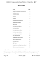
Table of Contents
SOFTWARE LICENSE AGREEMENT.......................................................................................... 1
New in Version 2.1........................................................................................................................... i
Introduction...................................................................................................................................... 1
Copy Protection............................................................................................................................... 2
Hardware Lock.................................................................................................................... 2
Cabling ............................................................................................................................................ 3
PC Serial Port...................................................................................................................... 3
AT Serial Port ..................................................................................................................... 4
The Cable ............................................................................................................................ 4
Interfaces ......................................................................................................................................... 5
C/C++.................................................................................................................................. 5
Visual Basic......................................................................................................................... 6
Important DLL Usage Notes............................................................................................................. 7
Broadcast Mode............................................................................................................................... 9
Error Codes ................................................................................................................................... 10
Function Summary.......................................................................................................................... 11
ArrayToWord: Assemble Array into Word ....................................................................... 12
Delays: Get/Set Communications Delays........................................................................... 13
ForceCoil: Write (Force) Single Coil ............................................................................... 15
ForceMultipleCoils: Write (Force) Multiple Coils ........................................................... 16
IOMapping: Control I/O Mapping ..................................................................................... 17
KeyPort: Get/Set Hardware Key port................................................................................ 18
Loopback: Loopback Test.................................................................................................. 19
PortSetup: Get/Set Communications Parameters................................................................ 20
ReadInputRegisters: Read Input Registers......................................................................... 22
ReadInputStatus: Read Input Status.................................................................................... 23
ReadOutputRegisters: Read Output Registers.................................................................... 24
ReadOutputStatus: Read Output Status............................................................................... 25
SendText: Send Text to Port .............................................................................................. 26
WordToArray: Break Word into Array ............................................................................. 27
WriteMultipleRegisters: Write Multiple Registers............................................................ 28
WriteRegister: Write Single Register ................................................................................ 29
Revision 2.210
June 6, 1998
Page i
MODBUS
Communications Driver
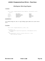
New in Version 2.1
SentinelC Key
In order to improve reliability, we have changed to a new type of hardware key manufactured by
Rainbow Technologies. Unlike previous keys, this key can be used on parallel ports other than LPT1.
To change the port where the Driver will look for the key, call MBDRV with the function synopsis:
MB_SetKeyport(PORTN);
where PORTN is the integer number of the parallel port where the key is located (1 to 3).
If you are using the default port, LPT1, there is no need to call the SetKeyport function. Rather than
checking the key once upon loading, the Driver now checks the key at random intervals. The Driver
will return a status of -2 if the key is not detected.
The SetKeyport command is described in more detail on page 18.
Support for “software key” protection has been discontinued.
MODBUS
Communications Driver
Introduction
The MBDRV Communications Driver is a Windows Dynamic Link Library (DLL) that enables Windows
programs to communicate with devices that understand the Gould MODBUS™ Process Control Protocol.
The driver provides an easy way for the user to develop programs that access a MODBUS device’s
points and registers. Information is passed using standard variables in the user’s host language. The
MODBUS driver handles all protocol formatting and variable conversion in both directions. MBDRV
always operates in “RTU” (Binary) mode.
The MODBUS driver can be used with any language that supports calls to external DLLs, including
Microsoft Access, Microsoft Visual Basic, Microsoft Visual C/C++, and Borland Delphi.
“Include” files
Many languages (such as C) have facilities for “include” or “unit” files that can establish constants and
function definitions. Wherever possible, ACS has supplied appropriate include files to make
programming easier.
Sample Files
Each version of the Driver is supplied with one or more demonstration programs. Please take the time
to examine and run these demonstrators; a few minutes with the samples can save you a lot of
frustration. Since the sample programs are known to run, you can use them to test your hardware setup.
If the demonstration programs won’t run, your own code probably won’t either. Also, since we wrote
the samples, it will be easy for us to diagnose problems encountered while working with them.
The sample programs can give you a head start on your own application by showing you proven ways
to construct an application program. In fact, you may wish to simply “cannibalize” the Demonstrator
programs to fit your own application.
Help!
If you have trouble, have any questions about how the driver works, or want advice about special
applications, please be sure to contact us... a two minute phone call could save you hours of frustration.
We are more than willing to help you use any unmodified software provided by ACS. We will also
answer questions about your programs (and help you debug programs that use MBDRV) as time permits.
If you find a bug in MBDRV, be sure to let us know. To help us fix the bug, document it as completely as
possible. If you are not sure whether the bug is in your program or the driver, please ship us your
program on an IBM compatible disk with documentation of the problem. If the problem is in the driver,
we will locate and repair it and return your disk as quickly as we can.
Revision 2.210
June 6, 1998
Page 1
MODBUS
Communications Driver
Copy Protection
Unfortunately, software piracy is a problem that plagues all program developers: the temptation to copy
an unprotected disk is great, and there is little actual danger to the pirate. But copy protection often offends users and sometimes involves unnecessary “hassles”. In order to keep everyone honest with a
minimum of trouble for the user, ACS has decided to issue all of its single-user Driver products in
copy-protected form.
Note. OEM versions of the Driver are not copy protected.
Hardware Lock
A Hardware Lock protects the single-user Driver. Programs protected with a Hardware Lock come on
ordinary floppy diskettes. You can (and should) make backup copies of the protected files, using the
DOS diskcopy command if you wish. The protection is incorporated into the files themselves and into
the locking device.
The Hardware Lock itself is a small device resembling a “gender changer.” It has two 25-pin
connectors on it, one male and one female.
When you run a program protected with a Hardware Lock, the software will periodically examine your
computer’s parallel printer port. If the correct Hardware Lock is found, the program runs normally. If
the locking device is not present, the program will not operate.
To use the Hardware Lock, simply copy the original program diskettes into a directory on your hard
disk. Next, plug the male end of the Hardware Lock device into your computer’s parallel printer port
(LPT1). If there is a printer already attached to your system, simply plug its cable into the female end
of the Hardware Lock.
Once you have attached the locking device, you are ready to run the software. Your computer should
operate just as before; the device is only active when the software specifically queries it. The Lock is
also transparent to printing.
By default, the Driver looks for the Hardware Key on printer port LPT1. To change the port where the
Driver will look for the key, call MBDRV with the function synopsis:
MB_SetKeyport(PORTN);
where PORTN is the integer number of the parallel port where the key is located (1 to 3). See the
description of the SetKeyport command below (page 18) for more details.
If you are using the default port, LPT1, there is no need to call the SetKeyport function. The Driver
will return a status of -2 if the key is not detected.
Page 2
June 6, 1998
Revision 2.210
MODBUS
Communications Driver
Cabling
Normally, your ACS software will be supplied with a cable suitable for connecting the IBM PC or
compatible to the MODBUS device.
However, some of our customers find that they need to make their own cables. This section describes
the cable and pinouts at each end of the connection. The serial port pinouts are included for reference,
since they are not often described in computer manuals.
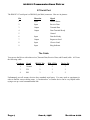
PC Serial Port
The IBM PC serial port is a DB25M (25-pin Male) connector. Here are its pinouts (pins not listed are
No Connection):
Pin
Direction
1
Shield Ground
2
Output
Transmit Data
3
Input
Receive Data
4
Output
Request to Send
5
Input
Clear to Send
6
Input
Data Set Ready
7
Signal
Ground
8
Input
Carrier Detect
9
Output+
Transmit Current Loop
11
Output-
Transmit Current Loop
18
Input+
Receive Current Loop
20
Output
Data Terminal Ready
22
Input
Ring Indicator
25
Input-
Receive Current Loop
Signal
Note: Only strictly IBM-compatible serial ports implement the 20ma current loop
interface.
Revision 2.210
June 6, 1998
Page 3
MODBUS
Communications Driver
AT Serial Port
The IBM PC AT serial port is a DB9M (9-pin Male) connector. Here are its pinouts:
Pin
Direction
Signal
1
Input
Carrier Detect
2
Input
Receive Data
3
Output
Transmit Data
4
Output
Data Terminal Ready
5
Ground
6
Input
Data Set Ready
7
Output
Request to Send
8
Input
Clear to Send
9
Input
Ring Indicator
The Cable
You can use the Driver with a three-wire (Transmit Data, Receive Data, and Ground) cable. ACS uses
the following cable:
Conductor
Signal
IBM PC Pin
IBM AT Pin
Device Pin
1
Ground
7
5
7
3
TD
2
3
3
4
RD
3
2
2
Unfortunately, not all MODBUS devices have standard serial ports. You may need to experiment in
order to find the correct cabling setup. A “breakout box” or similar device can be very helpful while
trying to set up a serial communications link.
Page 4
June 6, 1998
Revision 2.210
MODBUS
Communications Driver
Interfaces
C/C++
Calling the Driver from C is straightforward. Each
the Driver Dynamic Link Library.
MODBUS
command has its own function call within
To be able to call the Driver, you must add its import library to your C or C++ project. The import
library is called MBDRVDLL.LIB. This file tells the C linker which functions are contained in the Driver
DLL and how to find them.
In Microsoft Visual C++, you can add the import library by selecting the “Project / Add to Project /
Files” command, changing the “Files of type” selection to “Library files (.lib),” and then browsing to
MBDRVDLL.LIB.
You must also include the Driver DLL header file to be able to call Driver functions. This header file,
called MBDRVDLL.H, declares all the functions in the DLL. This is normally done with a directive like:
#include "mbdrvdll.h"
at the top of the C file.
The above steps will make the Driver DLL functions callable from within your program.
A typical C Driver call
Most MODBUS Driver calls follow the same general form. Calls that cause a
sent will include a MODBUS address and one or more parameters:
MODBUS
command to be
status = MB_ReadOutputStatus(Address, Start, Count, Values);
This command will read the status of digital outputs (coils) on the MODBUS device. The Address
parameter specifies the MODBUS device’s address on the network (a number from 1 to 255). The Start
parameter indicates the first coil to be read, and the Count parameter tells the Driver how many coils to
read. Lastly, the Values parameter is an array that will contain the coil states retrieved from the
MODBUS device.
Most MODBUS Driver DLL commands return a status code (assigned to the variable status in the
above example). This will be zero if the function completed successfully or nonzero in the event of an
error. Error codes can be interpreted from the table below, or you can get a text description using the
MB_ErrorString function.
Revision 2.210
June 6, 1998
Page 5
MODBUS
Communications Driver - Function QRF
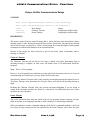
Visual Basic
Visual Basic provides good support for calling external DLLs like the MODBUS Driver. To define the
Driver’s function calls for your VB program you’ll need to add the file MBDEFS.BAS to your Visual
Basic project.
Once the definitions file has been added to your project, you can call the Driver as you would any other
function. For example, consider this code fragment:
Dim rc As Integer
Dim v(64) As Integer
rc = MB_ReadInputRegisters(6, 30010, 3, v(0))
These statements will read three Input Registers starting at address 30010 from MODBUS node 6 into the
array v. The Driver will return a status code (0 for success or an error code) that VB will assign to the
variable rc.
If the call completes successfully, then v(0) will contain the contents of register 30010, v(1) the
contents of 30011, and so on. The rest of the Driver’s functions are used in the same way.
Page 6
June 6, 1998
Revision 2.210
MODBUS
Communications Driver
Important DLL Usage Notes
MODBUS Integers
MODBUS is a 16-bit protocol. Accordingly, most of the integer variables used by the
DLL are 16-bit integers (short in most 32-bit Windows C compilers).
MODBUS
Driver
This is especially important when working with arrays. All arrays used by the Driver contain 16-bit
integers! Compiler type checking should help to protect you from inadvertent use of 32-bit integers (the
standard C int in 32-bit mode).
The only exception is register addresses, which can exceed the 16-bit integer limit of 32767. In a
typical C program, these would be passed as unsigned short. However, Visual Basic has no
unsigned integer type. Since many Driver developers use VB, register addresses are passed as long to
accommodate that language.
Loading the DLL
When creating a program that uses the MODBUS Driver DLL, you need to make sure that the DLL itself
is accessible, both during development and when installing your finished program on an end-user’s
machine. This means that the DLL must be in the application directory, the Windows System directory
(SYSTEM32 for Windows NT), or the Windows directory.
If Windows cannot find the Driver DLL file (called MBDRVDLL.DLL for the 32 bit version and
MBDRV16.DLL for the 16 bit version) when it is launching your application, it will close the program
after displaying a cryptic error message.
Programmers familiar with Windows API calls can make sure that Windows can find the DLL before
attempting to use it. This can help prevent a type of error that is often frustrating and confusing to endusers.
The “Missing” DLL
Users of the Windows 95 and NT platforms occasionally call ACS to report that we have shipped them
a disk containing no Driver DLL. Actually, the DLL is on the installation disk, but it can be “invisible”
due to settings in the Windows Explorer.
By default, the Windows Explorer hides certain “system” file types, presumably to protect those files
from accidental deletion. Among others, the Explorer considers any file with a .DLL extension to be a
system file.
To make system files visible, open an Explorer window and select the “View / Options…” dialog box.
In the “Hidden Files” frame, select the “Show All Files” radio button and click “OK.” This will make
the Driver DLL visible.
Revision 2.210
June 6, 1998
Page 7
MODBUS
Communications Driver - Function QRF
Differences between 16 and 32 bit DLLs
Though the code inside them is quite different, the 16 and 32-bit Driver DLLs function in much the
same way. For the developer, the key differences are in the file names:
16-bit
32-bit
Driver DLL
MBDRV16.DLL
MBDRVDLL.DLL
Driver Import Library
MBDRV16.LIB
MBDRVDLL.LIB
It’s worth repeating that all integers used by the Driver (except register addresses) are 16-bit integers
on both 16-bit and 32-bit platforms.
The 16-bit Driver can be used (though generally with reduced performance) on 32-bit platforms, but
the 32-bit Driver can only be used on Windows 95 or Windows NT. It cannot be used on 16-bit
Windows.
Page 8
June 6, 1998
Revision 2.210
MODBUS
Communications Driver
Broadcast Mode
Some MODBUS commands support “broadcast mode.” This mode essentially addresses the specified
command to all devices on the network.
To send a command in broadcast mode, specify an Address of zero.
Attempting to use an Address of zero with a command that does not support broadcast mode will cause
the Driver to return an error. Consult your MODBUS device’s documentation to see if it supports
broadcast mode, and if so, for which commands.
Revision 2.210
June 6, 1998
Page 9
MODBUS
Communications Driver - Function QRF
Error Codes
Error
Code
Sentinel key missing (copy protection)
-4
Could not receive
-3
Could not transmit
-2
Timeout
-1
No Error
0
Broadcast Mode not allowed
3
Illegal MODBUS address
4
Illegal count
5
Bad output (coil) address
6
Bad input address
7
Bad output register address
8
Bad input register address
9
Return frame check failed
10
User frame not ready
11
No incoming frame to dissect
12
Illegal command number
13
Bad return frame
14
CRC error
15
Bad pointer (e.g., illegal array address)
18
Illegal communications parameter
19
Any function that returns a nonzero value indicates an error condition.
MODBUS error return codes come back with 100 decimal added to them. MBDRV supports error codes
greater than 4 (if your device’s implementation of the MODBUS protocol uses them) in the same way.
Page 10
June 6, 1998
Revision 2.210
MODBUS
Communications Driver - Functions
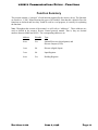
Function Summary
This section contains a “synopsis” of each function supported by the MODBUS driver. The functions
are listed in a “C-like” format showing the types of all variables. Note that this a hybrid of how the
functions are declared and how they would be used in a real program; it is strictly for explaining
the functions.
Note: Throughout this section of the manual, we will refer to “addresses”. These addresses are
used as defined in the MODBUS Process Control protocol manual. That is, they are decimal
numbers between 00000 and 49999. The corresponding addresses are:
Address
Writable
Type
0xxxx
Yes
Internal Discretes (digital points) and
Discrete Outputs (Coils)
1xxxx
No
Discrete (digital) Inputs
3xxxx
No
Input Registers
4xxxx
Yes
Holding Registers
Revision 2.210
June 6, 1998
Page 11
MODBUS
Communications Driver - Functions
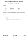
ArrayToWord: Assemble Array into Word
SYNOPSIS
void MB_ArrayToWord(const short Values[], short *Word);
Values
Word
Input Array
Output Value
Integer Array
Integer (by reference)
DESCRIPTION
This function is the converse of MB_WordToArray. It packs the first sixteen elements of the source
array Values into the destination integer Word. Element 0 of Values determines the status of Bit 0
of the destination integer.
MB_ArrayToWord checks each of the first 16 elements of the source array in turn. If the element is
nonzero, that bit of the target integer will be set. If the element is zero, the target bit will be
cleared.
Page 12
June 6, 1998
Revision 2.210
MODBUS
Communications Driver - Functions
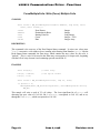
Delays: Get/Set Communications Delays
SYNOPSIS
short status = MB_GetDelays(long *charDelay, long *frameDelay);
short status = MB_SetDelays(long charDelay, long frameDelay);
status
charDelay
frameDelay
Error Return
Character Timeout
Frame Timeout
Integer
Long Integer (milliseconds)
Long Integer (milliseconds)
DESCRIPTION
The MODBUS protocol has no explicit framing, that is, it does not have codes that indicate when a
message begins or ends. Instead, the protocol relies on time. Specifically, the protocol says that the
end of each message is marked by a “silent” period lasting for at least the length of time required
to transmit two and one half characters at the current baud rate.
Because of this design, the Driver must use a pair of time delay values to determine when a
message is complete.
Character Timeout
The Character Timeout tells the Driver how long it should wait before determining that an
incoming message is complete. In most cases, the default value of 50 milliseconds should be
adequate.
Note. This is a 32-bit quantity.
However, if you frequently have problems receiving replies from the MODBUS device, or if you are
communicating at low baud rates, you may need to increase this value.
Note that the Character Timeout value is only used once an incoming message has started to arrive.
The Frame Timeout value determines how long the Driver will wait for an incoming message to
begin.
Reducing the Character Timeout value may provide increased throughput if you are trying to
sample at the maximum possible rate. However, values below 50 milliseconds may cause erratic
operation on some computers.
Frame Timeout
This value determines how long the control waits for an incoming MODBUS message to begin,
either in response to an outgoing command or while “listening” for an incoming command.
When you transmit a MODBUS command using any of the Driver’s command methods, it will wait
for a reply to begin arriving for the time specified by the Frame Timeout value. Once the reply
Revision 2.210
June 6, 1998
Page 13
MODBUS
Communications Driver - Functions
begins to arrive, the control uses the Character Timeout value to detect when the incoming message
is complete.
If no incoming message begins arriving during the time specified by the Frame Timeout value, the
DLL returns a Timeout Error.
EXAMPLE
MB_SetDelays(30, 4000);
This example sets the Character Timeout to 30 milliseconds and the Frame Timeout to 4000
milliseconds (4 seconds). This means that the Driver will wait up to 4 seconds for an incoming
frame to begin (either in response to an outgoing command, or when waiting for an unsolicited
incoming command). Once the frame has begun to arrive, any pause of 30 milliseconds or more
will mark the end of the frame.
Page 14
June 6, 1998
Revision 2.210
MODBUS
Communications Driver - Functions
ForceCoil: Write (Force) Single Coil
SYNOPSIS
short status = MB_ForceCoil(short Address, long Coil, short Value);
status
Address
Coil
Value
Error Return
Destination Address
Coil Number
New Value
Integer
Integer
Integer
Integer
DESCRIPTION
Writes a new value to a single Output coil (address 0xxxx). The Driver will set the Coil to 0 if
"New Value" is zero, or to 1 otherwise.
EXAMPLE
short status = MB_ForceCoil(3, 122, 1);
if (status != 0)
MessageBox(NULL, MB_ErrorString(status), "ForceCoil Error",
MB_OK);
else
MessageBox(NULL, "Coil 122 set to 1", "Force Coil",
MB_OK);
Revision 2.210
June 6, 1998
Page 15
MODBUS
Communications Driver - Functions
ForceMultipleCoils: Write (Force) Multiple Coils
SYNOPSIS
short status = MB_ForceMultipleCoils(short Address, long Start, short
Count, short Values[]);
status
Address
Start
Count
Values
Error Return
Destination Address
Starting Point No.
Count
Data
Integer
Integer
Long Integer
Integer < 1950
Integer Array
DESCRIPTION
This command is the converse of the Read Output Status command. It writes new values onto
"Count" consecutive coils (address 0xxxx) starting at the Starting Point Number (Start). Like the
Read Output Status command, the Data array, which contains the new values for the coils, is
"packed". This is, each 16-bit word in the Data array corresponds to 16 Output coils, beginning
with the LSb of array element 0 and continuing upwards toward Bit 15.
EXAMPLE
short bits[10];
// Value array
bits[0] = 0x27CD;
bits[1] = 127;
// Set up bit values
short status = MB_ForceMultipleCoils(11, 144, 23, bits);
if (status != 0)
MessageBox(NULL, MB_ErrorString(status), "ForceMultipleCoils Error",
MB_OK);
This sample will write a total of 23 coil values. The least significant bit of bits[0] will
determine the new value of Coil 144, Bit 1 of bits[0] corresponds to Coil 145, and so on,
through Bit 7 of bits[1], which corresponds to Coil 166.
Page 16
June 6, 1998
Revision 2.210
MODBUS
Communications Driver - Functions
IOMapping: Control I/O Mapping
SYNOPSIS
short status = MB_GetIOMapping(short *flag);
short status = MB_SetIOMapping(short flag);
status
flag
Error Return
Flag
Integer
Integer
DESCRIPTION
Normally, the MODBUS Driver DLL "maps" the Register and Coil addresses that you pass to
conform to the Protocol's specifications. For example, if you refer to Holding Register 40127, the
actual binary address transmitted by MBDRV will be 136, as defined by the Protocol.
However, if you are not working with Gould equipment, or if you need to control the actual
transmitted addresses, you can disable address mapping with this command.
Address Mapping is enabled by default. To disable Address Mapping, call MB_SetIOMapping
with flag equal to 0. Any nonzero value enables mapping.
Note. When I/O Mapping is on, the Driver DLL enforces proper register ranges
for all commands. For example, any command that takes an Input Register
address for an argument will return an error if the supplied address is not
between 30001 and 39999.
EXAMPLE
MB_SetIOMapping(0);
Revision 2.210
// Turn off I/O Mapping
June 6, 1998
Page 17
MODBUS
Communications Driver - Functions
KeyPort: Get/Set Hardware Key port
SYNOPSIS
short status = MB_GetKeyport(short *keyport);
short status = MB_SetKeyport(short keyport);
status
keyport
Return Code
Hardware Key Port
Integer
Integer
DESCRIPTION
By default, the Driver assumes that the Hardware Key is located on LPT1. However, you
can tell the Driver to look for the Key on another parallel printer port with this command.
keyport selects the port where the Key is located and can range from 1 (for LPT1) to the
highest port number supported by your system (usually 3).
EXAMPLE
// Select LPT2 for Hardware Key
MB_SetKeyport(2);
Page 18
June 6, 1998
Revision 2.210
MODBUS
Communications Driver - Functions
Loopback: Loopback Test
SYNOPSIS
short status = MB_Loopback(short Address, short *Diagnostic, short
*Info);
status
Address
DiagCode
Info
Error Return
Destination Address
Test to run
Test parameter
Integer
Integer
Integer (by reference)
Integer (by reference)
DESCRIPTION
Runs a diagnostic on the MODBUS device. The DiagCode parameter specifies which diagnostic to
run; the Info parameter may be used by some diagnostic operations and ignored by others. Some
diagnostic functions will return information via the Info parameter.
The specific diagnostics available vary from device to device, but diagnostic 0, the Loopback test,
is always implemented. This test simply sends back the Info value unchanged (so Info should be
the same before and after the call).
Returns 0 for success or an error code.
EXAMPLE
short dcode, dval;
dcode = 0;
dval = 1234;
// Run the the basic Loopback test
// Test value for loopback
short status = MB_Loopback(3, &dcode, &dval);
if (status != 0)
MessageBox(NULL, MB_ErrorString(status), "Loopback Error",
MB_OK);
else
MessageBox(NULL, (dval == 1234) ? "Device 3 Loopback OK" :
"Device 3 Loopback failed!",
"Loopback", MB_OK);
Revision 2.210
June 6, 1998
Page 19
MODBUS
Communications Driver - Functions
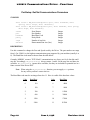
PortSetup: Get/Set Communications Parameters
SYNOPSIS
short status = MB_GetPortSetup(short *port, short *baudcode, short
*parity, short *stops, short *datasize);
short status = MB_SetPortSetup(short port, short baudcode, short parity,
short stops, short datasize);
Error Return
Port Number
Baud Rate Code
Parity Mode
Number of stop bits
Data transmission size (bits)
status
port
baudcode
parity
stops
datasize
Integer
Integer
Integer
Integer
Integer
Integer
DESCRIPTION
Use this command to change the Port and Speed used by the Driver. The port number can range
from 1 (for COM1:) to the highest communications port supported by your machine (usually 4 or
8). The Baud Rate code must be chosen from the table below.
Currently, MBDRV MODBUS "RTU Mode" communications are always set for 8 data bits and 1
stop bit. Accordingly, MB_GetPortSetup always returns 1 and 8 for the stop bits and data size
variables. MB_SetPortSetup ignores these variables, but they are included for potential use in a
future version of the Driver DLL.
Note. When using the MB_GetPortSetup function, you can supply NULL pointers
for any values you don’t want to retrieve.
The Baud Rate code must be an integer from 0 to 11. Here is a table of the baud rate values:
Code
Page 20
Baud Rate
Code
Baud Rate
0
110
6
4800
1
150
7
9600
2
300
8
19200
3
600
9
38400
4
1200
10
57600
5
2400
11
115200
June 6, 1998
Revision 2.210
MODBUS
Communications Driver - Functions
The Parity code must be one of the following values (“No Parity” is the default):
Code
Parity
0
None
1
Odd
2
Even
3
Mark
4
Space
Note: Not all PC serial ports support parity with 8 data bits (8 data bits are
required for RTU mode).
EXAMPLE
MB_SetPortSetup(2, 7, 0, 1, 8);
MessageBox(NULL, "Port 2 selected at 9600 baud.", "SetPortSetup",
MB_OK);
Revision 2.210
June 6, 1998
Page 21
MODBUS
Communications Driver - Functions
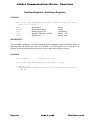
ReadInputRegisters: Read Input Registers
SYNOPSIS
short status = MB_ReadInputRegisters(short Address, long Start, short
Count, short Values[]);
status
Address
Start
Count
Values
Error Return
Destination Address
Starting Register No.
Number of Registers to Read
Return Array
Integer
Integer
Long Integer
Integer < 120
Integer Array
DESCRIPTION
This command is analogous to the Read Output Registers command, except it returns the values of
Input Registers, one register per return array element. The Driver permits you to read up to 120
registers in one operation, though your MODBUS device may require shorter requests.
EXAMPLE
short regs[10];
// Return value array
short status = MB_ReadInputRegisters(5, 30227, 3, regs);
if (status != 0)
MessageBox(NULL, MB_ErrorString(status), "ReadInputRegisters Error",
MB_OK);
Page 22
June 6, 1998
Revision 2.210
MODBUS
Communications Driver - Functions
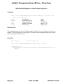
ReadInputStatus: Read Input Status
SYNOPSIS
short status = MB_ReadInputStatus(short Address, long Start, short
Count, short Values[]);
status
Address
Start
Count
Values
Error Return
Destination Address
Starting Input No.
Number of Inputs to Read
Return Array
Integer
Integer
Long Integer
Integer < 1950
Integer Array
DESCRIPTION
This routine is similar to RDOS (Read Output Status), except it reads the status of Input points
(address like 1xxxx). The Input values will be packed 16 bits per return array element, just as in
the Read Output command.
The MODBUS Driver allows you to read up to 1950 bits in one operation, but your MODBUS device
may have a lower transaction length limit.
EXAMPLE
short bits[10];
short status = MB_ReadOutputStatus(7, 10020, 23, bits);
Revision 2.210
June 6, 1998
Page 23
MODBUS
Communications Driver - Functions
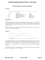
ReadOutputRegisters: Read Output Registers
SYNOPSIS
short status = MB_ReadOutputRegisters(short Address, long Start, short
Count, short Values[]);
status
Address
Start
Count
Values
Error Return
Destination Address
Starting Register No.
Number of Registers
Return Array
Integer
Integer
Long Integer
Integer < 120
Integer array
DESCRIPTION
This command returns the values of Output registers (address 4xxxx), one register per return array
element. The Driver permits you to read up to 120 registers in one operation, though your MODBUS
device may require shorter requests.
EXAMPLE
short regs[10];
// Return value array
short status = MB_ReadOutputRegisters(5, 40115, 3, regs);
if (status != 0)
MessageBox(NULL, MB_ErrorString(status), "ReadOutputRegisters Error",
MB_OK);
Page 24
June 6, 1998
Revision 2.210
MODBUS
Communications Driver - Functions
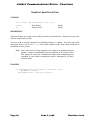
ReadOutputStatus: Read Output Status
SYNOPSIS
short status = MB_ReadOutputStatus(short Address, long Start, short
Count, short Values[]);
status
Address
Start
Count
Values
Error Return
Destination Device Address
Starting Coil Number
Number of Coils to Read
Return Array
Integer
Integer
Long Integer
Integer < 1950
Integer Array
DESCRIPTION
This function reads the status of Output Coils (address 0xxxx) on the MODBUS device. The coil
status values are returned in a "packed" format, with each bit in the return array corresponding to
one output coil. If the number of coils requested is not evenly divisible by 16, unused return array
bits will be set to 0.
The MODBUS Driver allows you to read up to 1950 bits in one operation, but your MODBUS device
may have a lower transaction length limit.
EXAMPLE
short bits[10];
// Return value array
short status = MB_ReadOutputStatus(12, 20, 23, bits);
if (status != 0)
MessageBox(NULL, MB_ErrorString(status), "ReadOutputStatus Error",
MB_OK);
This example reads a total of 23 bits starting at Output Coil Number 20 from the MODBUS device
with address 12. In the return array bits, element 0 will contain the current values of coils 20 35, with Bit 0 (the LSb) corresponding to Coil 20 and Bit 15 (the MSb) corresponding to Coil 35.
Element 1 of bits will contain Coils 36 - 42, with Bit 0 for Coil 36, Bit 7 for Coil 42, and Bits 8
- 15 set to 0.
If the function fails, the code sample displays an error Message Box, getting a string equivalent for
the error code using the MB_ErrorString function.
Revision 2.210
June 6, 1998
Page 25
MODBUS
Communications Driver - Functions
SendText: Send Text to Port
SYNOPSIS
short status = MB_SendText(const char *txt);
status
txt
Error Return
String to Send
Integer
String
DESCRIPTION
Sends an arbitrary text string to the serial port at the current baud rate. Strings are always sent
with one stop bit and no parity.
You may wish to use this command to send dialing strings to a modem. Any reply sent by the
destination device will be lost. Status will return a nonzero value if the string could not be
transmitted for some reason.
Note. Your code must wait long enough for the string to be transmitted before
issuing a MODBUS command that uses the serial port. The MODBUS Driver
DLL purges the serial port’s transmission buffer before transmitting each
command, so your string’s transmission could be interrupted if you don’t
include a delay.
EXAMPLE
if (MessageBox(NULL, "Dial phone?", "Send Text test",
MB_YESNO) == IDYES)
MB_SendText("AT D 1 800 555 1212\r\n");
Page 26
June 6, 1998
Revision 2.210
MODBUS
Communications Driver - Functions
WordToArray: Break Word into Array
SYNOPSIS
void MB_WordToArray(short Word, short Values[]);
Word
Values
Input Value
Output Array
Integer
Integer Array
DESCRIPTION
This command splits an integer into its 16 component bits. It stores the bits in the first sixteen
elements of the target array. Bit 0 (the least significant bit) is assigned to element 0 of the array.
EXAMPLE
short bits[16];
MB_WordToArray(0xCC55, bits);
char wrk[32];
char *p = wrk;
short *vp = bits + 15;
for (int n=15; n>=0; n--)
{
*p++ = (*vp--) ? '1' : '0';
if (!(n & 7)) *p++ = ' ';
if (!(n & 3)) *p++ = ' ';
}
// Add digits
// Add spacing
// Add spacing
*p = 0;
MessageBox(NULL, wrk, "0xCC55 as Binary is...", MB_OK);
Revision 2.210
June 6, 1998
Page 27
MODBUS
Communications Driver - Functions
WriteMultipleRegisters: Write Multiple Registers
SYNOPSIS
short status = MB_WriteMultipleRegisters(short Address, long Start,
short Count, short Values[]);
status
Address
Start
Count
Values
Error Return
Destination Address
Starting Register No.
Count
Data
Integer
Integer
Long Integer
Integer < 120
Integer Array
DESCRIPTION
Assigns values from Values to Count consecutive Holding registers (address 4xxxx) starting with
the register specified by Start. The Driver permits you to transmit up to 120 registers in one
operation, but your MODBUS device may have a lower limit.
EXAMPLE
short regs[10];
// Value array
regs[0] = 10;
regs[1] = 20;
regs[2] = 30;
// Set up register values
short status = MB_WriteMultipleRegisters(7, 40118, 3, regs);
if (status != 0)
MessageBox(NULL, MB_ErrorString(status),
"WriteMultipleRegisters Error", MB_OK);
Page 28
June 6, 1998
Revision 2.210
MODBUS
Communications Driver - Functions
WriteRegister: Write Single Register
SYNOPSIS
short status = MB_WriteRegister(short Address, long Register, short
Value);
status
Address
Register
Value
Error Return
Destination Address
Target Register
New Value
Integer
Integer
Long Integer
Integer
DESCRIPTION
This command changes the value of a single Holding register (address 4xxxx) on the
device.
MODBUS
EXAMPLE
short status = MB_WriteRegister(5, 40116, 120);
if (status != 0)
MessageBox(NULL, MB_ErrorString(status), "WriteRegister Error",
MB_OK);
else
MessageBox(NULL, "Device 5 register 40116 set to 120",
"Write Register", MB_OK);
Revision 2.210
June 6, 1998
Page 29