1
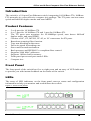
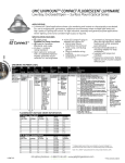
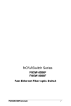
5-Port and 8-Port Compact Size Fast Ethernet Switch
Table of Contents
Table of Contents ........................................... 1
Packing List .................................................... 2
FCC Statement ............................................... 2
Introduction .................................................... 3
Product Features ....................................................... 3
Front Panel ................................................................ 3
LEDs .......................................................................... 3
Installation ...................................................... 4
Selecting a Site for the Switch ................................... 4
Connecting to Your Network ...................................... 5
Specifications................................................. 5
User’s Manual
1
5-Port and 8-Port Compact Size Fast Ethernet Switch
Packing List
Please inspect the contents and report any apparent damage or missing items
immediately to our authorized reseller.
•
•
•
The switch
User’s manual
One AC power cord
FCC Statement
The FCC (Federal Communications Commission) restricts the amount of radio
frequency emission and radiation coming from computer equipment. The Ethernet
switch stated in this manual has been tested and found to comply with the limits for
a Class A digital device pursuant to Part 15 of the FCC rules. These limits are
designed to provide reasonable protection against harmful interference when the
equipment is operated in a commercial environment. This equipment generates, uses,
and can radiate radio frequency energy, and if not installed and used in accordance
with the instruction manual, may cause harmful interference to radio
communications. Operation of this equipment in a residential area is likely to cause
harmful interference in which case the user is required to correct the interference at
his/her own expense. Any changes or modifications not expressly approved by the
manufacture would void the user’s authority to operate the equipment.
2
User’s Manual
5-Port and 8-Port Compact Size Fast Ethernet Switch
Introduction
The switch is a 5/8-port Fast Ethernet switch, integrating 10/100Base-TX (100BaseFX) networks in a cost-effective compact size package. The TX ports can auto sense
speed and half/full duplex modes and auto-MDIX.
Product Features
•
•
•
•
•
•
•
•
•
•
•
•
•
5 or 8-port for 10/100Base-TX.
4 or 7-port for 10/100Base-TX and 1-port for 100Base-FX.
The TX ports auto negotiate for 10/100Mbps speed, auto detect full/half
duplex mode, and auto-MDIX.
Choices of SC, ST, MT-RJ, VF-45, or LC connectors for FX ports.
Broadcast storming filter function.
True non-blocking architecture.
Full wire-speed forwarding rate.
Store-and-forward mechanism.
Back pressure and IEEE802.3x compliant flow control.
Supports 2048 MAC addresses.
Supports 1M bits buffer memory.
Front panel power and port status LEDs.
Compact size.
Front Panel
The front panel of the switch has five or eight ports and an array of LED indicators
to provide you with instant feedback on the status of the switch.
LEDs
The array of LED indicators on the front panel conveys status and configuration
information to help you monitor and troubleshoot the switch.
Figure 1: Front & rear panels
User’s Manual
3
5-Port and 8-Port Compact Size Fast Ethernet Switch
n Power This LED comes on when the switch is connected to the power.
o Port Status Each port has a LED, indicating the port status.
p Power Adapter Connect the supplied AC power cord to the receptacle on the
back of the switch, then plug the cord into a standard AC outlet with a voltage range
from 100 to 240 VAC.
Table 1: Port Status
LED
LNK/
ACT
State
Steady
Flashing
Indication
The port has established a valid network connection.
LNK stands for LINK.
The port is transmitting or receiving data.
ACT stands for ACTIVITY.
Installation
Selecting a Site for the Switch
As with any electronic device, you should place the switch where it will not be
subject to extreme temperatures, humidity, or electromagnetic interference.
Specifically, the site you select should meet the following requirements:
• The ambient temperature should be between 32 and 113 degrees Fahrenheit (0 to
45 degrees Celsius).
• The relative humidity should be less than 95 percent, non-condensing.
• Surrounding electrical devices should not exceed the electromagnetic field (RFC)
standards for IEC 801-3, Level 2 (3V/M) field strength.
• Make sure that the switch receives adequate ventilation. Do not block the
ventilation holes on the side of the switch or the fan exhaust port on the rear of the
switch.
• The power outlet should be within 1.8meter (6 feet) of the switch.
4
User’s Manual
5-Port and 8-Port Compact Size Fast Ethernet Switch
Connecting to Your Network
Connect network cables from computers or network segments to the TX (FX) ports
on the back of the unit.
Table 2: Cabling Information
Speed
Connector
Port Speed
Half/Full Duplex
Cable
100Base-TX
RJ-45
100/200 Mbps
100 m, Category 5 STP/UTP
10Base-T
RJ-45
10/20 Mbps
100 m, Category 3, 4, or 5
STP/UTP
100Base-FX
SC, ST, MTRJ, VF-45, or
LC
100/200 Mbps
Up to 2km, 50 or 62.5/125µm
Multi-mode fiber cable
SC
100/200 Mbps
Up to 75km, 9 or 10/125µm
Single-mode fiber cable
Multi-mode
100Base-FX
Single-mode
Specifications
Applicable Standards
LED Indicators
Cable
Switching Methods
Forwarding Rate
AC Input
Power consumption
Operating Temperature
IEEE 802.3, 10Base-T,
IEEE 802.3u, 100Base-TX/FX
Per unit – Power Status
Per Port – LNK/ACT
10Base-T 2-pair UTP/STP Cat. 3,4,5, up to 100m
100Base-TX 2-pair UTP/STP Cat.5, up to 100m
100Base-FX 50 or 62.5/125µm Multi-mode fiber optic cable,
up to 2km
100Base-FX 9 or 10/125µm Single-mode fiber optic cable,
up to 75km
Store-and-Forward
14,880pps for 10Mbps
148,810pps for 100Mbps
100~240VAC, 50-60Hz
3.22W Max.
0℃~45℃ (32℉~113℉)
Storage Temperature
-10℃~70℃ (14℉~158℉)
Humidity
Emissions
Dimensions
5%~95%, non-condensing
FCC Part 15 Class A, CE Mark Class A
252mm (W) x 134.3mm (D) x 35mm (H)
(9.92” (W) x 5.28” (D) x 1.38” (H))
compact size
1.6Kg (3.52lbs.)
Weight
User’s Manual
5
5-Port and 8-Port Compact Size Fast Ethernet Switch
Table of Contents
Table of Contents ........................................... 1
Packing List .................................................... 2
FCC Statement ............................................... 2
Introduction .................................................... 3
Product Features ....................................................... 3
Front Panel ................................................................ 3
LEDs .......................................................................... 3
Installation ...................................................... 4
Selecting a Site for the Switch ................................... 4
Connecting to Your Network ...................................... 5
Specifications................................................. 5
User’s Manual
1
5-Port and 8-Port Compact Size Fast Ethernet Switch
Packing List
Please inspect the contents and report any apparent damage or missing items
immediately to our authorized reseller.
•
•
•
The switch
User’s manual
One AC power cord
FCC Statement
The FCC (Federal Communications Commission) restricts the amount of radio
frequency emission and radiation coming from computer equipment. The Ethernet
switch stated in this manual has been tested and found to comply with the limits for
a Class A digital device pursuant to Part 15 of the FCC rules. These limits are
designed to provide reasonable protection against harmful interference when the
equipment is operated in a commercial environment. This equipment generates, uses,
and can radiate radio frequency energy, and if not installed and used in accordance
with the instruction manual, may cause harmful interference to radio
communications. Operation of this equipment in a residential area is likely to cause
harmful interference in which case the user is required to correct the interference at
his/her own expense. Any changes or modifications not expressly approved by the
manufacture would void the user’s authority to operate the equipment.
2
User’s Manual
5-Port and 8-Port Compact Size Fast Ethernet Switch
Introduction
The switch is a 5/8-port Fast Ethernet switch, integrating 10/100Base-TX (100BaseFX) networks in a cost-effective compact size package. The TX ports can auto sense
speed and half/full duplex modes and auto-MDIX.
Product Features
•
•
•
•
•
•
•
•
•
•
•
•
•
5 or 8-port for 10/100Base-TX.
4 or 7-port for 10/100Base-TX and 1-port for 100Base-FX.
The TX ports auto negotiate for 10/100Mbps speed, auto detect full/half
duplex mode, and auto-MDIX.
Choices of SC, ST, MT-RJ, VF-45, or LC connectors for FX ports.
Broadcast storming filter function.
True non-blocking architecture.
Full wire-speed forwarding rate.
Store-and-forward mechanism.
Back pressure and IEEE802.3x compliant flow control.
Supports 2048 MAC addresses.
Supports 1M bits buffer memory.
Front panel power and port status LEDs.
Compact size.
Front Panel
The front panel of the switch has five or eight ports and an array of LED indicators
to provide you with instant feedback on the status of the switch.
LEDs
The array of LED indicators on the front panel conveys status and configuration
information to help you monitor and troubleshoot the switch.
Figure 1: Front & rear panels
User’s Manual
3
5-Port and 8-Port Compact Size Fast Ethernet Switch
n Power This LED comes on when the switch is connected to the power.
o Port Status Each port has a LED, indicating the port status.
p Power Adapter Connect the supplied AC power cord to the receptacle on the
back of the switch, then plug the cord into a standard AC outlet with a voltage range
from 100 to 240 VAC.
Table 1: Port Status
LED
LNK/
ACT
State
Steady
Flashing
Indication
The port has established a valid network connection.
LNK stands for LINK.
The port is transmitting or receiving data.
ACT stands for ACTIVITY.
Installation
Selecting a Site for the Switch
As with any electronic device, you should place the switch where it will not be
subject to extreme temperatures, humidity, or electromagnetic interference.
Specifically, the site you select should meet the following requirements:
• The ambient temperature should be between 32 and 113 degrees Fahrenheit (0 to
45 degrees Celsius).
• The relative humidity should be less than 95 percent, non-condensing.
• Surrounding electrical devices should not exceed the electromagnetic field (RFC)
standards for IEC 801-3, Level 2 (3V/M) field strength.
• Make sure that the switch receives adequate ventilation. Do not block the
ventilation holes on the side of the switch or the fan exhaust port on the rear of the
switch.
• The power outlet should be within 1.8meter (6 feet) of the switch.
4
User’s Manual
5-Port and 8-Port Compact Size Fast Ethernet Switch
Connecting to Your Network
Connect network cables from computers or network segments to the TX (FX) ports
on the back of the unit.
Table 2: Cabling Information
Speed
Connector
Port Speed
Half/Full Duplex
Cable
100Base-TX
RJ-45
100/200 Mbps
100 m, Category 5 STP/UTP
10Base-T
RJ-45
10/20 Mbps
100 m, Category 3, 4, or 5
STP/UTP
100Base-FX
SC, ST, MTRJ, VF-45, or
LC
100/200 Mbps
Up to 2km, 50 or 62.5/125µm
Multi-mode fiber cable
SC
100/200 Mbps
Up to 75km, 9 or 10/125µm
Single-mode fiber cable
Multi-mode
100Base-FX
Single-mode
Specifications
Applicable Standards
LED Indicators
Cable
Switching Methods
Forwarding Rate
AC Input
Power consumption
Operating Temperature
IEEE 802.3, 10Base-T,
IEEE 802.3u, 100Base-TX/FX
Per unit – Power Status
Per Port – LNK/ACT
10Base-T 2-pair UTP/STP Cat. 3,4,5, up to 100m
100Base-TX 2-pair UTP/STP Cat.5, up to 100m
100Base-FX 50 or 62.5/125µm Multi-mode fiber optic cable,
up to 2km
100Base-FX 9 or 10/125µm Single-mode fiber optic cable,
up to 75km
Store-and-Forward
14,880pps for 10Mbps
148,810pps for 100Mbps
100~240VAC, 50-60Hz
3.22W Max.
0℃~45℃ (32℉~113℉)
Storage Temperature
-10℃~70℃ (14℉~158℉)
Humidity
Emissions
Dimensions
5%~95%, non-condensing
FCC Part 15 Class A, CE Mark Class A
252mm (W) x 134.3mm (D) x 35mm (H)
(9.92” (W) x 5.28” (D) x 1.38” (H))
compact size
1.6Kg (3.52lbs.)
Weight
User’s Manual
5