1
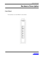
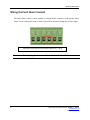
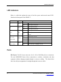
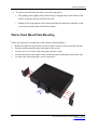
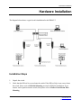
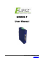
EIR405-T User Manual i Manual Documentation Number EIR405-T – 0912m www.bb-elec.com www.bb-europe.com EIR405 - T Documentation Number: EIR405 - T- 0912m Using domestic and imported parts by International Headquarters B&B Electronics Mfg. Co. Inc. 707 Dayton Road Ottawa, IL 61350 USA Phone (815) 433-5100 -- General Fax (815) 433-5105 Website: www.bb-elec.com European Headquarters B&B Electronics Ltd. Westlink Commercial Park Oranmore, Co. Galway, Ireland Phone +353 91-792444 -- Fax +353 91-792445 Website: www.bb-europe.com ©2008 B& B Electronics Mfg. Co. Inc. No part of this publication may be reproduced or transmitted in any form or by any means, electronic or mechanical, including photography, recording, or any information storage and retrieval system without written consent. Information in this manual is subject to change without notice, and does not represent a commitment on the part of B&B Electronics Mfg. Co. Inc. B&B Electronics Mfg. Co. Inc. shall not be liable for incidental or consequential damages resulting from the furnishing, performance, or use of this manual. All Brand names used in this manual are the registered trademarks of their respective owners. The use of trademarks or other designations in this publication is for reference purposes only and does not constitute an endorsement by the trademark holder ii Manual Documentation Number EIR405-T – 0912m www.bb-elec.com www.bb-europe.com Table of Contents Table of Contents 1. Overview ............................................................................................................................................................ 1 Introduction ....................................................................................................................................................... 1 Features ............................................................................................................................................................ 2 Packing List....................................................................................................................................................... 2 2. Hardware Description ....................................................................................................................................... 3 Front Panel ....................................................................................................................................................... 3 Top View ........................................................................................................................................................... 4 Wiring the Power Inputs .................................................................................................................................... 4 Wiring the Fault Alarm Contact ......................................................................................................................... 5 LED Indicators .................................................................................................................................................. 6 Ports.................................................................................................................................................................. 6 Cabling.............................................................................................................................................................. 8 3. Mounting Installation ...................................................................................................................................... 11 DIN-Rail Mounting........................................................................................................................................... 11 Wall Mount Plate Mounting ............................................................................................................................. 13 4. Hardware Installation ...................................................................................................................................... 14 Installation Steps............................................................................................................................................. 14 5. Troubleshooting .............................................................................................................................................. 16 6. Technical Specification................................................................................................................................... 17 iii Manual Documentation Number EIR405-T – 0912m www.bb-elec.com www.bb-europe.com Overview Overview Introduction The EIR405-T is an industrial DIN mount, unmanaged 5 port Gigabit Ethernet switch. High-Speed Transmissions The EIR405-T includes a switch controller that can automatically sense transmission speeds (10/100/1000 Mbps). The RJ-45 interface can also be auto-detected, so MDI or MDI-X is automatically selected and a crossover cable is not required. All Ethernet ports have memory buffers that support the store-and-forward mechanism. This assures that data is properly transmitted Dual Power Input To reduce the risk of power failure, the EIR405-T provides two 12 to 48 VDC power inputs. If the power fails, the switch will automatically switch to the secondary power input. Also if the power goes out the corresponding P1 or P2 LED will go out and the Fault LED will light. The contacts for the alarm output will also open. Flexible Mounting The EIR405-T can be DIN or Panel mounted. The compact design is suitable for space-constrained environment such as a small cabinet. Advanced Protection The power line input on the EIR405-T supports up to 3,000 VDC EFT protection, which secures the equipment against unregulated voltages and makes the system safer and more reliable. The Ethernet ports support up to 6,000 VDC ESD protections which makes the switch suitable for harsh environments. Wide Operating Temperature The operating temperature of the EIR405-T is -40 to 75oC. This wide range allows the switch to be used in some of the harshest industrial environments that exist. 1 Manual Documentation Number EIR405-T – 0912m www.bb-elec.com www.bb-europe.com Overview Easy Troubleshooting LED indicators make troubleshooting quick and easy. There are 2 LED’s for each port that display the link status and transmission speed. Three LED’s P1, P2 and Fault help you diagnose if power is present. Features • • • • Provides 5 x 10/100/1000Base-T Mbps Ethernet ports. Supports full/half duplex flow control Supports auto-negotiation (10/100/1000) Supports MDI/MDI-X auto-crossover • • • • • • Supports Jumbo Frame of 9Kbytes Supports surge (EFT) protection 3,000 VDC for power input Supports 6,000 VDC Ethernet ESD protection Supports redundant 12 to 48 VDC power inputs Provides flexible mounting: DIN-rail or Panel Mounting Supports operating temperatures from -40 to 75oC Packing List • • • • 2 (1) EIR405-T, 5 Port Gigabit Industrial Ethernet Switch (1) Quick Start Guide (1) CD ROM with User Manual (2) Wall Mounting Bracket and Screws Manual Documentation Number EIR405-T – 0912m www.bb-elec.com www.bb-europe.com Hardware Description Hardware Description Front Panel The Front Panel view of the EIR405-T is shown below. 3 Manual Documentation Number EIR405-T – 0912m www.bb-elec.com www.bb-europe.com Hardware Description Top View The top panel view of the EIR405-T is equipped with one terminal block connector that consists of two 12 to 48 VDC power inputs and the fault alarm output. Wiring the Power Inputs Follow the steps below to insert the power wires. 1. Insert the positive and negative wires into the V+ and V- contacts on the terminal block connector. 2. Tighten the wire-clamp screws to prevent the wires from becoming loose. 4 Manual Documentation Number EIR405-T – 0912m www.bb-elec.com www.bb-europe.com Hardware Description Wiring the Fault Alarm Contact The fault alarm contact is in the middle of terminal block connector as the picture shows below. If one of the power sources fails a fault will be detected causing the circuit to open. Insert the wires into the fault alarm contact (No. 3 & 4) Note 5 The wire gauge for the terminal block should be 12 to 24 AWG. Manual Documentation Number EIR405-T – 0912m www.bb-elec.com www.bb-europe.com Hardware Description LED Indicators Below is a table that explains the status of each the power and network status LED’s found on the front panel of the EIR405-T. LED Color P1 Green P2 Fault Green Description On Power input 1 is active Off Power input 1 is inactive On Power input 2 is active Off Power input 2 is inactive On Power input 1 or 2 is inactive Red Off Ports 1 to 5 (Upper LED) Ports 1 to 5 (Lower LED) Green Green Power inputs 1 and 2 are both active, or no power is present On Connected to network Flashing Networking is active Off Not connected to network On Connected to network at speed of 1000Mbps Off Not connected to 1000Mbps network Ports RJ-45 ports: The RJ-45 ports auto-sense for 10, 100 or 1000 Mbps devices connections. The auto MDI/MDIX feature allows connections to switches, workstation and other equipment without changing straight through or crossover cabling. The charts below show the cable pin assignments for straight through and crossover cables. 6 Manual Documentation Number EIR405-T – 0912m www.bb-elec.com www.bb-europe.com Hardware Description RJ-45 Pin Assignments Pin Number Assignment 1 Tx+ 2 Tx- 3 Rx+ 6 Rx- “+” and “-” signs represent the polarity of each wire pair. Note All ports on the EIR405-T support automatic MDI/MDI-X operation, you can use straight-through cables (See Figure below) for all network connections to PCs or servers, or to other switches or hubs. In straight-through cables, pins 1, 2, 3, and 6, at one end of the cable, are connected straight through to pins 1, 2, 3 and 6 at the other end of the cable. The table below shows the 10BASE-T / 100BASE-TX MDI and MDI-X port pin outs. Pin MDI-X Signal Name MDI Signal Name 1 Receive Data plus (RD+) Transmit Data plus (TD+) 2 Receive Data minus (RD-) Transmit Data minus (TD-) 3 Transmit Data plus (TD+) Receive Data plus (RD+) 6 Transmit Data minus (TD-) Receive Data minus (RD-) Straight Through Cable Schematic 7 Manual Documentation Number EIR405-T – 0912m www.bb-elec.com www.bb-europe.com Hardware Description Cross Over Cable Schematic Cabling Use unshielded twisted-pair (UTP) or shielded twisted-pair (STP) cable. 10Mbps: Use category 3, 4, 5 or greater cable 100Mbps: Use category 5 or greater 1000Mbps: Use category 5e or greater cable Cable distances should be less than 100 meters (328 ft.) long. 8 Manual Documentation Number EIR405-T – 0912m www.bb-elec.com www.bb-europe.com Hardware Description RJ-45 Male Plug 87 6 5 4 321 1 23 4 5 6 78 1 23 4 5678 RJ-45 Female Color standard EIA!TIA T568A T><+ T><- RX+lt27Zl RX- c=::J Ethernet Patch Cable RJ45 Pin# Green!White Tracer 1 Green 2 Orange!White Tracer 3 Blue 4 Blue!White Tracer 5 Orange 6 Brown!White Tracer 7 Brown 8 Color standard EIA!TIA T568A Pin# RJ45 1 Green!White Tracer 2 Green 3 Orange!White Tracer 4 Blue 5 Blue!White Tracer 6 Orange 7 Brown!White Tracer 8 Brown Ethernet Crossover Cable Green!White Tracer Green Orange!White Tracer Blue 1 2 3 4 1 2 3 4 5 Orange!White Tracer Orange Green!White Tracer Brown!White Tracer Brown Brown!White Tracer 7 Brown 8 "A" is earlier 9 Manual Documentation Number EIR405-T- 0912m 'MMN.bb-elec.com 'MMN.bb-europe.com Hardware Description Color standard EIA!TIA T568B Ethernet Patch Cable RJ45 Pin# TX+ [?ZZl] Orange!White Tracer 1 TX- c=::J Orange 2 Green!White Tracer J RX+ PJiilll"'... Blue 4 Blue!White Tracer 5 PJiilll"'... Green 6 RX- PJiilll"'... Brown!White Tracer 78 Brown - Color standard Pin# RJ45 1 Orange!White Tracer 2 Orange J Green!White Tracer 4 Blue 5 Blue!White Tracer 6 Green 7 Brown!White Tracer 8 Brown Ethernet Crossover Cable Green!White Tracer J J Orange!White Tracer 7 7 Blue RJ45 Pin# EIA!TIA T568B Orange!White Tracer 1 Orange 2 Blue Blue!White Tracer Green Brown!White Tracer Brown "B" is most recent Pin# RJ45 1 Green!White Tracer 2 Green - lt'llZl PJiilll"'... 4 5 6 4 Brown!White Tracer 5 Brown 6 Orange PJiilll"'... 8 8 Blue!White Tracer PJiilll"'... Common Ethernet Cr ossover Cables may only cross connect the Orange & Green pairs c=::J Hardware Description 10 Manual Documentation Number EIR405-T- 0912m \fVININ. bb-elec.com \fVININ. bb-europe.com Mounting Installation Mounting Installation DIN-Rail Mounting The DIN rail clip comes screwed on to the switch, from the factory. If the DIN rail clip is not screwed on the switch, please see the following figure to re-attach the DIN-Rail clip. Then follow the steps below to hang the switch onto a DIN rail. Rear Panel of the switch DIN-Rail 1. Use the screws to screw the DIN rail clip onto the switch. 2. To remove the DIN rail clip, reverse step 1. 11 Manual Documentation Number EIR405-T – 0912m www.bb-elec.com www.bb-europe.com Mounting Installation 3. First, insert the top of DIN rail clip onto the piece DIN rail track. 4. Then, lightly push the bottom of the switch so it can snap the rest of the way onto the DIN rail track. 5. Check that the switch is held tightly to the DIN rail track. 12 Manual Documentation Number EIR405-T – 0912m www.bb-elec.com www.bb-europe.com Mounting Installation 6. To remove the switch from the track, reverse the steps above. • First pushing down lightly on the switch will give enough room for the bottom of the switch to clear the bottom of the DIN rail track. • Pulling slowly at the bottom of the switch will bring the switch out so that the switch can now be carefully lifted off the DIN rail track. Wall or Panel Mount Plate Mounting Follow the steps below to mount the switch with the wall mount plates. 1. Remove the DIN rail clip from the switch; loosen the screws to remove the DIN rail clip. 2. Place the wall mount plate on the side panels of the switch. 3. Use the screws to screw the wall mount plate onto the switch. 4. Use the hook holes at the corners of the wall mount plates to hang the switch on the wall. 5. To remove the wall mount plate, reverse steps above. 13 Manual Documentation Number EIR405-T – 0912m www.bb-elec.com www.bb-europe.com Hardware Installation Hardware Installation The diagram below shows a typical switch installation for the EIR405-T. Installation Steps 1. 2. 14 Unpack the switch. Check that the DIN rail is screwed onto the switch. If the DIN rail clip is not screwed onto the switch. Please refer to DIN-Rail Mounting section for DIN-Rail installation. If you want to wall or panel mount the switch, then please refer to Wall or Panel Mount Plate Mounting. Manual Documentation Number EIR405-T – 0912m www.bb-elec.com www.bb-europe.com Hardware Installation 3. Apply power to the switch. If you need help with this please refer to the Wiring the Power Inputs section. The power LED on the switch will light up. Please refer to the LED Indicators section for meaning of LED lights. 4. 5. Prepare the twisted-pair, Ethernet cable for connection. Insert one side of cable into one of the switches Ethernet ports and the other side of the cable to the network device you want connected ex: switch, PC or Server. The port LED on the Industrial switch will light up when the cable is connected to the network device. Please refer to the LED Indicators section for LED light meaning. 6. When all connections are made and the LED lights show normal activity the installation is complete. 15 Manual Documentation Number EIR405-T – 0912m www.bb-elec.com www.bb-europe.com Troubleshooting Troubleshooting 16 • Verify that you are using a power supply ranging from 12 to 48VDC. than 48VDC could cause damage to the switch. • Be sure the proper cable is used in your network. manual for help. • Diagnosing LED Indicators: The switch can be monitored through the LED indicators on the front panel of the switch. The LED’s can help describes common problems you may encounter and where you may find possible solutions, to assist in identifying problems. • If the power indicators do not light on when power is applied, you may have a problem with the power supply. Check for loose power connections, power losses or surges at the power outlet. • If the switch LED’s represent normal operating mode and the cable connections are correct and no data is transmitted or received through the switch, contact your Network Administrator for network configuration and status help. Applying more Refer to the Cabling section of this Manual Documentation Number EIR405-T – 0912m www.bb-elec.com www.bb-europe.com Technical Specification Technical Specification Communications Compatibility IEEE 802.3, 802.3u, 802.3ab IEEE 802.3x LAN Transmission Distance Transmission Speed 10/100/1000Base-T Up to 100 m Up to 1000 Mbps 7,926pps (default) Broadcast Storm Rate Limit Interface Connectors 5 x RJ-45 (5-port 10/100/1000TX) 6-pin removable screw terminal (power input & fault relay output) LED Indicators Unit: P1, P2, Fault Ethernet port: Link/Active (100Mbps) Link (1000Mbps) Power Power Consumption Power Input Fault Output 4.6 W 2 x Unregulated 12 to 48 VDC 1 Relay Output Mechanism 17 Dimensions (WxDxH) 30 x 95 x 140 mm (1.2 x 3.7 x 5.5 inches) Enclosure IP30, Metal shell with solid mounting kits Manual Documentation Number EIR405-T – 0912m www.bb-elec.com www.bb-europe.com Technical Specification Protection ESD (Ethernet) Surge (EFT for power) Reverse Power 6,000 VDC 3,000 VDC Yes Environment Operating Temperature Operating Humidity -40 to 75oC (-40 to 167oF) 5% to 95% (non-condensing) Storage Temperature -40 to 85oC (-40 to 185oF) Certifications Safety EMC UL, cUL, CE EN60950-1 FCC Class A, CE EN61000-4-2 (ESD) CE EN61000-4-3 (RS) CE EN61000-4-4 (EFT) CE EN61000-4-5 (Surge) CE EN61000-4-6 (CS) CE EN61000-4-8 CE EN61000-4-11 CE EN61000-4-12 CE EN61000-6-2 CE EN61000-6-4 Free Fall Shock Vibration 18 IEC60068-2-32 IEC60068-2-27 IEC60068-2-6 Manual Documentation Number EIR405-T – 0912m www.bb-elec.com www.bb-europe.com