1
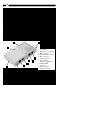
Wiring Tester
Remote Cable Tester for RJ45 RJ11 and BNC
Installation Manual
REMOTETEST
1
Overview
The StarTech.com REMOTETEST cable tester is a palm-sized unit with four kinds of
connectors: RJ45, RJ11, USB and BNC, for the testing of today’s most popular media.
This unit can be used to verify the condition of cables, both before and after their
installation. The separable passive module is connected to the remote end of the
installed network cabling.
The tester also offers easy operating; the user begins by testing by simply pushing a
button. Multiple LEDs give a clear indication of testing status and go off automatically,
to maximize power saving.
Features
• Detachable module for testing remote points
• Open/Short wiring testing
• Connected wires display
• Ethernet 10Base2/10Base5 termination value detector
• No wire or termination indicator
• Wrong connection/Non-parallel connection
Specifications
Indicators
Battery Good/Battery Low
(Green/Yellow)
No Connection/No Terminator LED
(Yellow)
Non-Parallel/50 Ohm LED (Yellow)
Connected/25 Ohm LED (yellow)
Short LED (Red)
S, C/a, 2, 3, 4, 5, 6, 7, 8 LEDs (Yellow)
Connectors
RJ45 x 2, RJ11 x 2, USB A x 1, USB B x 1,
BNC x 1
Cable Length
200m for all connectors
Power
9V Alkeline battery
Size
145 x 86 x 26 mm (5.7 x 3.39 x 1.03")
Weight
185g (6.53 oz)
Getting Started
Operating Instruction
To test the cable not installed (RJ45, RJ11, USB, and BNC):
1. Connect one end of the cable to the master’s proper connector, and the other end to
the remote module.
2. Press the test button.
3. When the LEDs stop flashing the result is ready to be read.
2
To test the cables already installed (RJ45, RJ11, USB and BNC):
1. Connect one end of the cable to the master’s proper connector.
2. Separate the remote module, then connect it to the cable’s remote point.
3. Press the test button.
4. When the LEDs stop flashing the result is ready to be read.
Note 1: Do not connect the tester to a live circuit.
Note 2: Do not test more than one cable simultaneously.
To test Ethernet 10Base2/10Base5 terminator value (BNC):
1. Disconnect any one of the T-connectors from its attached node on the 10Base2
segment that you want to test, and link the T-connector to the testers BNC port.
2. Press the test button.
3. When the LEDs stop flashing the result is ready to be read.
Note 1: Before conducting the test, verify there isn’t any activity on the 10Base2 segment.
Note 2: If testing LED fails to light after pressing the test button, replace the battery.
Key components
7
3
1
4
6
B
2
C
A
5
1. Start button
2. Battery cover (on back)
3. BNC connector
4. Shielded RJ45 connector
5. RJ11 connector
6. USB B connector
7. LED indicator
(Refer to Appendix A)
A. Shielded RJ45
connector
B. RJ11 connector
C. USB A connector
How to Read the Results
Testing RJ45, RJ11, USB and BNC
Short Test
When LEDs for Short, S, and 3 are on and the tester beeps four times, it means the Wire
number 3, 4 and 5 are short.
3
Connected Test
When LEDs for Connected, S, and 1...8 LED are on and the tester beeps three times, it
means the shielding and indicated wires are pin-to-pin connected between cable’s two
ends. For instance, if a standard Ethernet 10BaseT unshielded twisted-paired cable (UTP)
are tested, the LEDs for Connected, Wire 1, 2, 3 and 6 will turn on.
Note: If there is only one wire connected inside a cable between the cable’s two ends, the
tester will state no wire connected.
Connected and Non-parallel Test
LEDs for both Connected and Non-parallel, and LEDs for Wire S, 1, 2, ...8 turn on and
the tester beeps twice, it means the shielding and indicated wires are connected between
cable’s two ends, but not pin-to-pin straight connection. It is possibly a wrong connection
cable or a cross-over cable.
Note: If there are only two wires connected inside a cable between the cable’s two ends,
the tester cannot detect whether these two wires are pin-to-pin connected or not. It only
indicates two wires connected.
No Connection Test
When the No Connection LED turns on and the tester beeps once, it means there is no
connection between the master and the remote module. It happens when no cable is
connected with the tester.
Testing BNC Connector
LED for Short, S and C
When LEDs for Short, S and C, turn on and the tester beeps four times, it means the
shield and the center of the BNC connector is short.
LED for 25 OHM, S and C
When the LEDs for the 25 OHM, S and C turn on and the tester beeps three times, it
means the tested cable it terminated with correct terminated resister value.
LED for 50 OHM, S and C
When the LEDs for 50 OHM, S and C turn on and the tester beeps twice, it means a
single ending terminated resister value is detected. It may be caused by a broken cable,
or the terminator at one end is not linked well.
LED for No Terminator
When the LED for No Terminator turns on and the tester beeps once, it means no resister
value detected between shielding and center. The cable is probably not terminated
(all open).
4
Appendix A - LED Indicators
The Remote Cable Tester has a total of 14 LEDs, 9 horizontal indicating each individual
wire inside a cable, and 5 vertical displaying a cable connection status. You can read the
result from the combination of lit horizontal and vertical LEDs.
• S (Yellow) Shielding
• C/1 (Yellow) Center of coaxial cable (BNC) or wire a of TP cable (RJ45), telephone cord
(RJ11) or USB
• 2, 3, 4, ...8 (Yellow) Wire 2, 3, 4, ...8
• Short (Red) Short condition between wires, or between shielding and center of BNC
connector.cable are detected.
• Connected or 25 Ohm (Green) A straight-through connection cable is detected. Or a
standard Ethernet 10Base2 and 10Base5 terminated with 25 Ohm cable is detected.
• Non-parallel or 50 Ohm A non-straight-through connection cable is detected. Or an
Ethernet 10Base2 and 10BAse5 cable with one end termination value (50 Ohm)
is detected.
• No connection/no terminator (Yellow) No cable or terminator is scanned.
• Battery good/battery low (Yellow/Green) It shows the battery status. If LED is green
the battery condition is good, if the LED is yellow the battery condition is poor.
Replace the old battery with a new one when the LED fails to remain lit during
normal operation.
Appendix B
UTP Colour Code
Pair 1
Pair 2
Pair 3
Pair 4
White-Blue (W-BL)
Blue (BL)
White-Orange (W-O)
Orange (O)
White-Green (W-G)
Green (G)
White-Brown (W-BR)
Brown (BR)
Wiring Scheme
T568A
1 W-G
2 G
3 W-O
4 BL
5 W-BL
6 O
7 W-BR
8 BR
T568B
1 W-O
2 O
3 W-G
4 BL
5 W-BL
6 G
7 W-BR
8 BR