1
OPERATION MANUAL FA-9520 (FA-9520 Mode) Frame Synchronizer FA-95PS FA-95DACBL FA-95AIO FA-95CO FA-95D-D/DE-E FA-95ALA FA-95RU* FA-10DCCRU* 3rd Edition - Rev.2 SOFT Ver. 2.03 – higher Edition Revision History Edit. Rev. 1 2 3 3 3 1 2 Date 2013/03/15 2013/05/15 2013/05/31 2014/06/02 2014/07/08 Description Where First edition (V0100) Added FA-95ALA, FA-95AIO, FA-95D-D/DE-E, FA-95CO options and Auto Video Optimizer feature. Added FA-95RU option Corrected SNMP List Added FA-10DCCRU option. 6-10-6, etc. 18 7-3, 9-8-2, 24-1, etc Software Versions and Supported Options Version *1 FPGA1: 1.00 or higher FPGA2: 1.00 or higher FPGA3: 1.00 or higher SOFT: 1.00 or higher FPGA1:1.10 or higher FPGA2:1.10 or higher FPGA3:1.00 or higher SOFT:1.10 or higher Supported Feature/Option FA-95PS FA-95DACBL Note First edition FA-95ALA FA-95AIO (FA-95AVO) FA-95D-D FA-95DE-E FA-95CO Supports FA-95ALA, FA-95AIO, FA-95DE/DE-E, FA-95CO options and Auto Video Optimizer feature. FA-95D-D and FA-95DE-E communication methods with the main unit modified to support FA-95ALA. Supported FA-95D-D/FA-95DE-E versions: FPGA1: 1.00 FPGA2: 2.00 (1.10 or lower is inoperative in this unit.) FPGA1:1.10 or higher FPGA2:1.10 or higher FPGA3:1.00 or higher SOFT:2.00 or higher FA-95RU FPGA1: 1.12 or higher FPGA2: 1.10 or higher FPGA3: 1.00 or higher SOFT: 8.03 or higher FA-10DCCRU Modified FA-95RU to add FA-9520 support FA-95RU Ver. 6.00 or higher-compatible Added BY-PASS function to FA-95AIO GPI Added option slot change warning feature Enhanced FA-95ALA measurement accuracy FPGA1: 1.00 FPGA2: 1.10 Modified FA-10DCCRU to add FA-9520 support FA-10DCCRU SOFT Ver. 1.00, FPGA1/2 Ver 1.00 or higher-compatible *1 Version information can be seen as described in section 7-8 “UNIT Ver.”. 2 Precautions Important Safety Warnings [Power] Operate unit only on the specified supply voltage. Caution Disconnect power cord by connector only. Do not pull on cable portion. Stop Do not place or drop heavy or sharp-edged objects on power cord. A damaged cord can cause fire or electrical shock hazards. Regularly check power cord for excessive wear or damage to avoid possible fire / electrical hazards. [Grounding] Ensure unit is properly grounded at all times to prevent electrical shock hazard. Caution Hazard Do not ground the unit to gas lines, units, or fixtures of an explosive or dangerous nature. Ensure power cord is firmly plugged into AC outlet. Caution [Operation] Hazard Hazard Do not operate unit in hazardous or potentially explosive atmospheres. Doing so could result in fire, explosion, or other dangerous results. Do not allow liquids, metal pieces, or other foreign materials to enter the unit. Doing so could result in fire, other hazards, or unit malfunction. If foreign material does enter the unit, turn power off and disconnect power cord immediately. Remove material and contact authorized service representative if damage has occurred. [Transportation] Caution Handle with care to avoid shocks in transit. Shocks may cause malfunction. When you need to transport the unit, use the original packing materials or alternate adequate packing. 3 [Circuitry Access] Do not remove covers, panels, casing, or access circuitry with power applied to the unit! Turn power off and disconnect power cord prior to removal. Internal servicing / adjustment of unit should only be performed by qualified personnel. Stop Do not touch any parts / circuitry with a high heat factor. Capacitors can retain enough electric charge to cause mild to serious shock, even after power is disconnected. Capacitors associated with the power supply are especially hazardous. Avoid contact with any capacitors. Hazard Unit should not be operated or stored with cover, panels, and / or casing removed. Operating unit with circuitry exposed could result in electric shock / fire hazards or unit malfunction. [Potential Hazards] Caution If abnormal smells or noises are noticed coming from the unit, turn power off immediately and disconnect power cord to avoid potentially hazardous conditions. If problems similar to above occur, contact authorized service representative before attempting to again operate unit. [Rack Mount Brackets, Ground Terminal, and Rubber Feet] Caution To rack mount or ground the unit, or to install rubber feet, do not use screws or materials other than those supplied. Otherwise, it may cause damage to the internal circuits or components of the unit. If you remove the rubber feet attached on the unit, do not reinsert the screws securing the rubber feet. [Consumables] Caution The consumables used in unit must be replaced periodically. For further details on which parts are consumables and when they should be replaced, refer to the specifications at the end of the Operation Manual. Since the service life of the consumables varies greatly depending on the environment in which they are used, they should be replaced at an early date. For details on replacing the consumables, contact your dealer. 4 Upon Receipt Unpacking FA-9520 units and their accessories are fully inspected and adjusted prior to shipment. Operation can be performed immediately upon completing all required connections and operational settings. Check your received items against the packing lists below. FA-9520 ITEM FA-9520 AC Cord Rack Mount Brackets CD-ROM Quick Setup Guide QTY 1 1 set 1 set 1 1 REMARKS (Incl. ladder strap/retaining clip assembly) EIA standard type (Including 4 screws.) FA-9520/FA-9500 User Manuals (PDF) Option ITEM REMARKS Remote Control Unit Redundant power supply unit (with AC cord and FA-95PS 1 set AC cord retaining clip) Digital audio expansion cable (to expand digital audio I/O up to 8 inputs and 8 outputs.) FA-95DACBL * 1 Normally installed in slot B. FA-95D-D * 1-2 Dolby E/Digital decoder Dolby E encoder FA-95DE-E* 1-2 FA-95D-D option required for FA-95DE-E installation. Analog component I/O expansion card FA-95AIO * 1-2 (with dedicated connection cable: PC-3307-1) FA-95ALA * 1-2 Automatic Loudness Adjustment card FA-10DCCRU 1 Remote Control Unit for color correction. * In FA-9520 mode, FA-95D-D, FA-95DE-E, FA-95AIO and FA-95ALA option cards can be installed into either or both option slots A and B. In FA-9500 mode, only the card in slot A is effective, if 2 of the same option cards are installed into both slots. Also, only the card in slot A is effective, when FA-95D-D and FA-95DE-E are installed into both slots. The FA-95DACBL option can be installed into either option slot A or B, however, not into both slots. FA-95RU QTY 1 Software Option ITEM QTY REMARKS FA-95CO * 1 Changeover * FA-95CO is effective only in FA-9500 mode. Software installation can be verified in the “SOFT OPTION1” and “SOFT OPTION2” menus. IMPORTANT The FA-9520 has 2 operational modes; FA-9500 mode, in which the unit operates/functions almost the same as the former FA-9500, and FA-9520 mode with 2 independently operational frame synchronizers. After purchase, select an FA-9520 operational mode for the first time. Refer to section 7-1 “MU OPERATION” for details on the mode selection procedure. This operation manual describes the operation in FA-9520 mode. When operating in FA-9500 mode, refer to the separate FA-9520 operation manual (FA-9500 mode). 5 Check Check to ensure no damage has occurred during shipment. If damage has occurred, or items are missing, inform your supplier immediately. Trademark Microsoft and Windows are either registered trademarks or trademarks of Microsoft Corporation in the United States and/or other countries. Pentium and Intel Core are trademarks of Intel Corporation in the U.S. and/or other countries. Firefox is a registered trademark of the Mozilla Foundation. Dolby is a trademark of Dolby Laboratories. All other trademarks are trademarks or registered trademarks of their respective owners. Rack Mounting FA-9520/RPS can be mounted to EIA standard rack units. When rack mounting a unit, remove the rubber feet and use the accessory rack mount brackets (rack ears). Installing the AC Cord Retaining Clip Secure the AC cord with the supplied ladder strap/retaining clip assembly to prevent accidental removal from the FA-9520. Installing the clip 1) Wrap the retaining clip around the AC cord. (with the anchor of the ladder strap toward the unit.) 2) Insert the anchor into the hole next to the AC IN socket. 3) Lightly fasten the clip around the AC cord. 4) Plug in the power cord. 5) Slide the clip on the ladder strap toward the plug. 6) Fasten the clip tightly. 7) Gently pull on the AC cord to ensure it is secured. 5) 6) 2) 4) 1) 2) 3) 3) Unpluging the AC cord Push the tab on the retaining up to unfasten the clip. Push the tab on the ladder strap up and slide the clip back. Unplug the AC cord. 1) 2) 6 Table of Contents 1. Prior to Starting ....................................................................................................................... 15 1-1. Welcome .......................................................................................................................... 15 1-2. Features ........................................................................................................................... 15 1-3. FA-95LG GUI Download .................................................................................................. 15 2. Panel Descriptions .................................................................................................................. 16 2-1. Front Panel ...................................................................................................................... 16 2-2. Rear Panel ....................................................................................................................... 18 2-3. Internal Settings ............................................................................................................... 21 2-3-1. Dipswitch Settings..................................................................................................... 21 3. Connections ............................................................................................................................ 22 3-1. For 2-Channel Frame Synchronizer Use ......................................................................... 22 3-2. For HD/SD-SDI Simul Output........................................................................................... 23 3-3. To Embed AES Input Signals on SDI Signals .................................................................. 24 3-4. To Embed Analog Audio Signals on SDI Signals ............................................................. 25 3-5. Connecting a Computer ...................................................................................................26 3-6. Connecting to the REMOTE (GPI) Connector.................................................................. 27 4. Front Panel Operation ............................................................................................................. 28 4-1. Powering ON.................................................................................................................... 28 4-2. Basic Operation ............................................................................................................... 28 4-2-1. Accessing Menus ...................................................................................................... 29 4-2-2. Menu Buttons ............................................................................................................ 30 4-2-3. Arrow Buttons ........................................................................................................... 32 4-2-4. Consecutive Viewing of Settings ............................................................................... 32 4-2-5. Page Jump Feature .................................................................................................. 33 4-2-6. Changing Setting Values .......................................................................................... 34 4-2-7. Resetting to Default ..................................................................................................35 4-2-8. Switching Between 2-Channel Frame Synchronizers ............................................... 35 5. VIDEO Menus ......................................................................................................................... 37 5-1. VIDEO PROC AMP (PROCESS) ..................................................................................... 37 5-2. COLOR CORRECTOR (C.C.).......................................................................................... 37 5-2-1. WHITE LEVEL .......................................................................................................... 37 5-2-2. BLACK LEVEL .......................................................................................................... 38 5-2-3. GAMMA LEVEL ........................................................................................................ 38 5-2-4. COLOR CORRECT (C.C.) ........................................................................................ 39 5-2-5. Color Corrector and AVO Modes .............................................................................. 40 5-3. CONV (UP/DOWN/CROSS CONVERTER) ..................................................................... 41 5-3-1. CONV MODE ............................................................................................................ 42 5-3-2. CONV Conversion Table .......................................................................................... 43 5-3-3. CONV SIZE/POS ...................................................................................................... 43 5-3-4. CONV CROPPING ................................................................................................... 44 5-3-5. CONV IMPROVE ...................................................................................................... 45 7 5-3-6. CONV SIDE RGB ..................................................................................................... 46 5-4. Auto Video Optimizer (AVO)............................................................................................ 47 5-4-1. AVO SETTING ......................................................................................................... 47 5-4-2. AVO SETUP ............................................................................................................. 48 5-4-2-1. About Scene Cut Detection and Frame Delay Settings ..................................... 49 5-4-3. USER1 - 5 LEVEL SET ............................................................................................ 50 5-4-4. USER1, 2 AREA SET ............................................................................................... 53 5-4-4-1. Manual Level Adjustment .................................................................................. 54 5-5. CLIP (VIDEO CLIP) ......................................................................................................... 55 5-5-1. YPbPr/RGB CLIP ..................................................................................................... 55 5-5-2. COMPOSITE CLIP ................................................................................................... 56 5-5-3. VIDEO CLIP Setting Ranges .................................................................................... 56 5-6. VIDEO INPUT SELECT (IN SEL) .................................................................................... 58 5-6-1. FS INPUT SELECT .................................................................................................. 58 5-6-2. VIDEO INPUT SET .................................................................................................. 59 5-6-3. ANC DETECT LINE ................................................................................................. 60 5-6-4. ANC DETECT SEL................................................................................................... 60 5-6-5. AIO A IN MODE ....................................................................................................... 61 5-6-6. AIO B IN MODE ....................................................................................................... 61 5-7. VIDEO OUT SELECT (OUT SEL) ................................................................................... 62 5-7-1. OUTPUT ASSIGN .................................................................................................... 62 5-7-2. AIO A ASSIGN ......................................................................................................... 63 5-7-3. AIO B ASSIGN ......................................................................................................... 64 5-7-4. ANC DATA EMBED ................................................................................................. 65 5-7-5. ANC EMBED LINE ................................................................................................... 66 5-8. VIDEO OPTION (VIDEO OP) .......................................................................................... 68 5-8-1. Logo Generator ........................................................................................................ 68 5-8-1-1. LOGO SELECT ................................................................................................. 68 5-8-1-2. KEYER SET ...................................................................................................... 69 5-8-1-3. Logo Position Setting Range ............................................................................. 69 5-9. VIDEO SYSTEM (VIDEO SYS) ....................................................................................... 70 5-9-1. FS MODE SET ......................................................................................................... 70 5-9-2. HD PHASE SET ....................................................................................................... 71 5-9-3. SD PHASE SET ....................................................................................................... 72 5-9-4. VIDEO POSITION .................................................................................................... 73 5-9-5. FREEZE SET ........................................................................................................... 73 5-9-6. ANC SET .................................................................................................................. 74 5-9-7. ANC LOSS SET ....................................................................................................... 75 5-9-8. WSS AFD ERROR ................................................................................................... 76 5-9-9. AUDIO GROUP ........................................................................................................ 76 5-9-10. TEST SIGNAL ........................................................................................................ 77 5-9-11. BY-PASS SETTING ............................................................................................... 77 5-9-12. AIO BY-PASS SET................................................................................................. 78 5-9-13. SD LINE MASK ...................................................................................................... 79 5-9-14. COMPOSITE SET1 ................................................................................................ 80 8 5-9-15. COMPOSITE SET2 ................................................................................................ 80 5-10. Various Signal Status Display (STATUS) ...................................................................... 81 5-10-1. UNIT ALARM .......................................................................................................... 81 5-10-2. VIDEO IN STATUS ................................................................................................. 82 5-10-3. VIDEO OPTION INPUT .......................................................................................... 83 5-10-4. VIDEO OUT STATUS ............................................................................................. 84 5-10-5. VIDEO OPTION OUTPUT ...................................................................................... 84 5-10-6. AUDIO IN DETECT1 ............................................................................................... 85 5-10-7. AUDIO IN DETECT2 ............................................................................................... 85 5-10-8. AUDIO OUTPUT1 ................................................................................................... 86 5-10-9. AUDIO OUTPUT3 ................................................................................................... 86 5-10-10. EMB 1 IN AUDIO .................................................................................................. 87 5-10-11. EMB 2 IN AUDIO .................................................................................................. 88 5-10-12. AES IN AUDIO ...................................................................................................... 89 5-10-13. ANALOG IN AUDIO .............................................................................................. 89 5-10-14. SDI 1/2 OUT AUDIO ............................................................................................. 90 5-10-15. SDI 3/4 OUT AUDIO ............................................................................................. 91 5-10-16. AES OUT AUDIO .................................................................................................. 91 5-10-17. ANALOG OUT AUDIO .......................................................................................... 92 5-10-18. Dolby OPA AUX .................................................................................................... 92 5-10-19. Dolby OPB AUX .................................................................................................... 93 5-10-20. AFD IN STATUS ................................................................................................... 94 5-10-21. ANC1 IN STATUS................................................................................................. 94 5-10-22. ANC1 IN STATUS 1-2 .......................................................................................... 95 5-10-23. ANC OUT ..............................................................................................................95 5-10-24. S2016 OUT ...........................................................................................................95 5-10-25. VI OUT .................................................................................................................. 96 5-10-26. WSS OUT .............................................................................................................96 5-10-27. ANC OUT1 ............................................................................................................97 6. AUDIO Settings....................................................................................................................... 98 6-1. SDI AUDIO Settings (SDI AUDIO) ................................................................................... 98 6-1-1. EMB1 IN GAIN ..........................................................................................................98 6-1-2. EMB1 OUT MONO ................................................................................................... 98 6-1-3. EMB1 IN SET ...........................................................................................................99 6-1-4. EMB1 OUT CLOCK ................................................................................................ 100 6-1-5. EMB2 IN GAIN ........................................................................................................ 101 6-1-6. EMB2 OUT MONO ................................................................................................. 101 6-1-7. EMB2 IN SET ......................................................................................................... 102 6-1-8. EMB2 AUDIO CLOCK ............................................................................................ 103 6-2. AES AUDIO Settings (AES AUDIO) ............................................................................... 104 6-2-1. AES IN GAIN .......................................................................................................... 104 6-2-2. AES HYSTERESIS ................................................................................................. 104 6-2-3. AES OUT MONO .................................................................................................... 105 6-2-4. AES I/O SETUP ...................................................................................................... 105 9 6-3. ANALOG AUDIO Settings (ANALOG) ........................................................................... 106 6-3-1. ANALOG IN LEVEL................................................................................................ 106 6-3-2. ANALOG IN GAIN .................................................................................................. 106 6-3-3. ANALOG OUT LEVEL............................................................................................ 106 6-3-4. ANALOG OUT MONO ............................................................................................ 107 6-3-5. ANALOG IN SYSTEM ............................................................................................ 107 6-4. OUTPUT GAIN CONTROL ........................................................................................... 108 6-4-1. MASTER OUT GAIN .............................................................................................. 108 6-4-2. EMB1 OUT GAIN ................................................................................................... 108 6-4-3. EMB2 OUT GAIN ................................................................................................... 109 6-4-4. AES OUT GAIN ...................................................................................................... 109 6-4-5. ANALOG OUT GAIN .............................................................................................. 110 6-5. AUDIO MAPPING (MAPPING)...................................................................................... 111 6-5-1. EMB1 OUT REMAP ............................................................................................... 111 6-5-2. EMB2 OUT REMAP ............................................................................................... 112 6-5-3. AES OUT REMAP .................................................................................................. 113 6-5-4. ANALOG OUT REMAP .......................................................................................... 114 6-6. AUDIO DELAY Settings ................................................................................................ 115 6-6-1. EMB1 IN DELAY .................................................................................................... 115 6-6-2. EMB2 IN DELAY .................................................................................................... 115 6-6-3. AES IN DELAY ....................................................................................................... 115 6-6-4. ANALOG IN DELAY ............................................................................................... 116 6-7. DOWN MIX1 SET.......................................................................................................... 117 6-7-1. DOWN MIX1 ASSIGN ............................................................................................ 118 6-8. DOWN MIX2 SET.......................................................................................................... 119 6-8-1. DOWN MIX2 ASSIGN ............................................................................................ 120 6-9. AUDIO MODE SET (MODE) ......................................................................................... 121 6-9-1. EMB1 SRC MODE ................................................................................................. 121 6-9-2. EMB2 SRC MODE ................................................................................................. 121 6-9-3. AES SRC MODE .................................................................................................... 122 6-9-4. EMB1 POLARITY ................................................................................................... 122 6-9-5. EMB2 POLARITY ................................................................................................... 122 6-9-6. AES POLARITY ..................................................................................................... 123 6-9-7. ANALOG POLARITY.............................................................................................. 123 6-9-8. Dolby A POLARITY ................................................................................................ 124 6-9-9. Dolby B POLARITY ................................................................................................ 124 6-10. AUDIO OPTION (AUDIO OP) ..................................................................................... 125 6-10-1. FA-95D-D / FA-95DE-E ........................................................................................ 125 6-10-1-1. Dolby AUX OUT ............................................................................................ 125 6-10-1-2. Dolby DEC IN ................................................................................................ 126 6-10-1-3. Dolby DECODER REFERENCE ................................................................... 127 6-10-1-4. Dolby DOWNMIX .......................................................................................... 127 6-10-1-5. Dolby DECODER GAIN ................................................................................ 128 6-10-1-6. Dolby ENCODER INPUT .............................................................................. 129 6-10-1-7. Dolby ENCODER SETTING .......................................................................... 130 10 6-10-1-8. METADATA INPUT........................................................................................ 131 6-10-2. Automatic Loudness Adjustment (FA-95ALA) ....................................................... 132 6-10-2-1. LOUDNESS MEASUREMENT ...................................................................... 132 6-10-2-2. LOUDNESS CONTROL ENABLE.................................................................. 133 6-10-2-3. LOUDNESS CONTROL SETTINGS .............................................................. 134 6-10-2-4. LOUDNESS CHANNEL ASSIGNMENT ........................................................ 135 6-10-2-5. LOUDNESS STANDARD .............................................................................. 136 6-11. AUDIO SYSTEM Settings (AUDIO SYS) ..................................................................... 137 6-11-1. FADE IN / OUT ..................................................................................................... 137 6-11-2. DIGITAL AUDIO.................................................................................................... 138 6-11-3. AUDIO ERR SENSE ............................................................................................. 138 6-11-4. DIGITAL SILENCE................................................................................................ 140 7. Other Settings & Information (OTHER) ................................................................................. 141 7-1. FS1/FS2 COPY.............................................................................................................. 141 7-2. MU OPERATION ........................................................................................................... 142 7-2-1. Important Note on Changing the Operation Mode .................................................. 142 7-2-2. FA-9520 Operation Mode Change Procedure ........................................................ 142 7-3. CONTROL SETTING ..................................................................................................... 143 7-4. FRONT OPERATION ....................................................................................................143 7-5. FRONT PANEL SET ...................................................................................................... 143 7-6. GPI SETTING ................................................................................................................ 144 7-7. NETWORK INFO ........................................................................................................... 147 7-8. UNIT Ver. ....................................................................................................................... 147 7-9. OPTION A Ver. .............................................................................................................. 148 7-10. OPTION B Ver. ............................................................................................................ 148 7-11. OTHER OPTION.......................................................................................................... 149 7-12. SOFT OPTION1........................................................................................................... 149 7-13. SOFT OPTION2........................................................................................................... 149 8. Event Memory ....................................................................................................................... 150 8-1. EVENT LOAD ................................................................................................................ 150 8-2. EVENT SAVE ................................................................................................................ 151 8-3. EVENT SETUP ..............................................................................................................151 8-4. Parameters That Are Not Stored in Event Memories ..................................................... 152 8-5. Note on Event Memory Operation.................................................................................. 152 9. Control via WEB Browser...................................................................................................... 153 9-1. Connecting via a WEB Browser ..................................................................................... 153 9-2. VIDEO Settings .............................................................................................................. 154 9-2-1. FS Input Select .......................................................................................................155 9-2-2. Auto Video Optimizer (AVO) ................................................................................... 156 9-2-2-1. About Scene Cut Detection and Frame Delay Settings ................................... 158 9-2-2-2. User 1 - 5 LEVEL SET ..................................................................................... 159 9-2-2-3. User Area 1, 2 .................................................................................................. 161 9-2-3. Frame Delay ...........................................................................................................162 9-2-4. Proc Amp ................................................................................................................ 163 11 9-2-5. BY-PASS Setting.................................................................................................... 164 9-2-6. Converter ............................................................................................................... 165 9-2-7. Color Corrector ....................................................................................................... 169 9-2-8. Video Test Signal ................................................................................................... 172 9-2-9. YPbPr/RGB Clip ..................................................................................................... 173 9-2-10. Output Assign ....................................................................................................... 174 9-2-11. Composite Clip ..................................................................................................... 176 9-3. AUDIO Settings ............................................................................................................. 177 9-3-1. SDI Input ................................................................................................................ 178 9-3-2. AES Audio Input Settings ....................................................................................... 180 9-3-3. Analog Audio Input ................................................................................................. 182 9-3-4. Audio Delay (SDI / AES / Analog) .......................................................................... 183 9-3-5. SRC Mode (SDI / AES) .......................................................................................... 184 9-3-6. Audio Output Polarity (SDI / AES / Analog) ............................................................ 185 9-3-7. Audio Mapping ....................................................................................................... 186 9-3-8. Audio Master Gain Settings .................................................................................... 188 9-3-9. Down Mix Setting ................................................................................................... 189 9-3-10. SDI Audio Output Settings ................................................................................... 191 9-3-11. AES Audio Output Settings .................................................................................. 192 9-3-12. Analog Audio Output Settings .............................................................................. 192 9-3-13. Dolby E/Digital Decoder ....................................................................................... 193 9-3-14. Dolby AUX Output Select ..................................................................................... 196 9-3-15. Dolby E Encoder .................................................................................................. 197 9-3-16. Automatic Loudness Adjustment (FA-95ALA) ...................................................... 199 9-4. SYSTEM Settings.......................................................................................................... 202 9-4-1. FS1/FS2 Video System .......................................................................................... 202 9-4-2. Audio System ......................................................................................................... 207 9-4-3. ANC Settings .......................................................................................................... 210 9-4-4. Composite Settings ................................................................................................ 214 9-5. GPI ................................................................................................................................ 215 9-6. Utility Settings................................................................................................................ 217 9-6-1. Event Control.......................................................................................................... 218 9-6-2. Backup Parameter.................................................................................................. 219 9-6-3. Downloading a MIB File ......................................................................................... 220 9-6-4. Event Data Backup................................................................................................. 221 9-7. Status Display ............................................................................................................... 222 9-7-1. Unit/Video Status.................................................................................................... 222 9-7-2. Audio Status ........................................................................................................... 225 9-7-3. Unit Information ...................................................................................................... 227 9-7-4. ANC Status ............................................................................................................ 228 9-8. Network Settings ........................................................................................................... 231 9-8-1. Network Information ............................................................................................... 231 9-8-2. NETWORK SETTING ............................................................................................ 231 9-8-3. SNMP SETTING .................................................................................................... 232 9-8-4. TRAP SETTING ..................................................................................................... 234 12 9-8-5. USER SETTING ..................................................................................................... 235 9-8-6. Restart .................................................................................................................... 235 10. Downmix Block Diagram .....................................................................................................236 11. ANALOG/DIGITAL Audio Input/Output Level ...................................................................... 237 11-1. Analog Output Level Relative to the Digital Input Level ............................................... 237 11-2. Digital Output Level Relative to the Analog Input Level ............................................... 238 12. Analog Audio Connection....................................................................................................239 13. Dolby E Decoder/Encoder Channel Assignment Table ....................................................... 240 14. REMOTE............................................................................................................................. 241 14-1. REMOTE Connector ....................................................................................................241 14-2. GPI Input Circuit........................................................................................................... 241 14-3. GPI Input Control ......................................................................................................... 242 14-4. GPI Output Circuit ........................................................................................................ 243 15. How to Install the FA-95DACBL .......................................................................................... 244 15-1. Procedure .................................................................................................................... 244 15-2. Installation Confirmation ..............................................................................................245 16. FA-95AIO Option ................................................................................................................ 246 16-1. FA-95AIO Pin Assignments ......................................................................................... 246 16-2. FA-95AIO Switch Settings............................................................................................ 247 17. System Requirements ......................................................................................................... 248 18. About SNMP (Simple Network Management Protocol) ....................................................... 249 19. FA-9520 Ancillary Data Packet Name List .......................................................................... 262 20. About AFD (Active Format Description) .............................................................................. 264 20-1. AFD Codes .................................................................................................................. 265 20-2. Aspect Ratio Conversion with AFD .............................................................................. 267 20-3. AFD Supported Video Formats .................................................................................... 271 20-4. AFD Based Auto Aspect Conversion Settings ............................................................. 271 20-5. How to Insert AFD Data to Output Video Signals......................................................... 272 20-6. AFD Code Abbreviations ............................................................................................. 273 21. About Closed Captioning .................................................................................................... 275 21-1. Closed Captioning Setting Procedure .......................................................................... 275 22. Verification After Option Card Removal/Replacement ........................................................ 276 22-1. Alert ............................................................................................................................. 276 22-2. Verification After Dolby Option Removal/Replacement ................................................ 276 22-3. Verification After FA-95AIO Removal/Replacement..................................................... 276 22-4. Verification After FA-95ALA Removal/Replacement .................................................... 277 23. Expansion Slots A / B Alert ................................................................................................. 277 24. Specifications and Dimensions ........................................................................................... 278 24-1. Unit Specifications ....................................................................................................... 278 13 24-2. External Dimensions ................................................................................................... 281 Index ........................................................................................................................................ 282 14 1. Prior to Starting 1-1. Welcome Congratulations! By purchasing FA-9520 Frame Synchronizer you have entered the world of FOR-A and its many innovative products. Thank you for your patronage and we hope you will turn to FOR-A products again and again to satisfy your video and audio needs. FOR-A provides a wide range of products, from basic support units to complex system controllers, which have been increasingly joined by products for computer video based systems. Whatever your needs, talk to your FOR-A representative. We will do our best to be of continuing service to you. 1-2. Features The FA-9520 is a multipurpose signal processor loaded with all the functions you need for video production. 3G-SDI, HD/SD-SDI, and analog composite I/O is supported in addition to its functionality as a frame synchronizer. The unit provides dual up/down/cross/aspect converters, color corrector, and automatic video optimizer (AVO) as standard features, allowing for the conversion of many types of video and audio signals. Numerous additional optional features include analog component I/O, logo generator, Dolby E encoder and Dolby E decoder. By combining these varied options, a single unit can provide optimal functionality for all your video production scene requirements, including transmission, live production, news reporting, video production, editing and distribution. As long as you have the FA-9520, you will never need another piece of peripheral video equipment! Standard Features 3G-SDI/HD-SDI/SD-SDI/Analog Composite I/O Digital/Analog Audio I/O Main Converter (Up/Down/Cross/Aspect conversion) Second Converter (Up/Down/Cross/Aspect conversion) Color Corrector Auto Video Optimizer (AVO) Powerful Frame Synchronizer Performance Logo Generator Other Features Video delay 2D/3D comb filter for Y/C separator (composite) Web browser-based monitoring and control possible SNMP monitoring and partial control function Additional Features Redundant power supply unit Digital audio expansion cable Changeover function (in FA-9500 mode only) Dolby E/Digital decoder and Dolby E encoder Analog component I/O Automatic Loudness Adjustment Function Remote control unit via Ethernet 1-3. FA-95LG GUI Download The FA-9520 Logo generator function is designed to be used with logo management software, FA-95LG GUI, enabling logo data import to FA-9520 via Ethernet. The FA-95LG GUI can be downloaded from FOR-A’s website: http://www.for-a.com/products/fa9500/fa95lg_gui.zip. The operation manual for the FA-95LG GUI will download automatically along with the software. 15 2. Panel Descriptions 2-1. Front Panel POWER LOCK VIDEO IN FAN ALARM ON AUDIO IN DC POWER BY-PASS GENLOCK OFF EVENT No REMOTE F1 F2 F3 F4 DISPLAY AREA HD / SD FRAME S YS N C H R O N IZ E R FA-9500 Name F1 F2 F3 F4 UNITY UNITY UNITY UNITY PROCESS CC SDI AUDIO AES AUDIO AVO MAPPING CLIP DELAY VIDEO OP AUDIO OP VIDEO SYS AUDIO SYS CONV1 ANALOG CONV2 MASTER IN SEL DOWNMIX OUT SEL MODE STATUS OTHER VIDEO AUDIO Description Ref. Used to turn the unit ON / OFF. Pressing the "|" side turns on the 1 POWER switch power. 4-1 In FA-9500 mode: Lit when pressed, and the buttons and controls on the front panel except this LOCK button are disabled. To enable the disabled buttons and controls, press and hold this button down for several seconds. LOCK button (FA-9500 mode) In FA-9520 mode: Used to select FS1 or FS2. There are linked menus that can be 2 changed simultaneously by pressing the FS1/LOCK and FS2/LOCK FS1/LOCK buttons simultaneously. See 4-2-8 “2-channel frame synchronizer (FA-9520 mode) switching” for details. Disables operation only for FS1 when pressed and held down. Press and hold this button down again to unlock operation. * Both FS1 and FS2 LOCKs can be set simultaneously to disable all other buttons except themselves. In FA-9500 mode: Ineffective In FA-9520 mode: Used to select FS1 or FS2. There are linked menus that can be changed simultaneously by pressing FS1/LOCK and FS2/LOCK buttons simultaneously. See 4-2-8 “Switching Between 2-Channel FS2/LOCK 3 4-2-8 (FA-9520 mode) Frame Synchronizers” for details. Disables operation only for FS2 when pressed and held down. Press and hold this button down again to unlock operation. * Both FS1 and FS2 LOCKs can be set simultaneously to disable all other buttons except themselves. 4 EVENT button Used to save and load events. 8 5-6-1 Lit green Input signal is present in FS1 or FS2. 5-10-2 VIDEO IN 5-6-1 Unlit No input signal is present in FS1 or FS2. 5-10-2 One or more assigned audio output signals Lit green (FS1, FS2 embedded, AES and/or analog 6-5 audio) are present. AUDIO IN No assigned audio signal (FS1, FS2 embedded, AES and/or analog audio) is Unlit 6-5 present. Lit green Genlock signal input is present. 5-10-2 5 Status indicator GENLOCK Unlit No genlock signal input is present. 5-10-2 Lit green CONTROL SETTING is set to REMOTE. REMOTE 7-3 Unlit CONTROL SETTING is set to LOCAL. A power failure has occurred. Turn the power 5-10-1 DC POWER Lit red of the unit OFF, and contact your supplier. *1 Unlit Power supply is normal. 5-10-1 One or more fans have failed. Turn the power Lit red of the unit OFF, and replace the failed fans if 5-10-1 FAN ALARM needed. Unlit All fans are operating normally. 5-10-1 6 Menu display Used to display menus and make operational settings 4-2 16 Controls (F1-F4) Used to change operational settings. Turn and select values. The Unity buttons return the settings to the default values. UNITY buttons Used to move between parameters. Single-arrow buttons (Indicators light up to indicate the accessible direction.) 8 Arrow buttons Used to move between menus (same as the Double-arrow menu buttons). (Indicators light up to indicate the buttons accessible direction.) 9 Menu buttons Used to select menus. *1 The DC POWER indicator functions when the optional FA-95PS is installed. 7 17 4-2 4-2 4-2 4-2 2-2. Rear Panel FA-9520 B REMOTE AC100 - 240V 50/60 Hz IN2 LAN1 FAN1 IN1 OUT1 OUT2 IN2 OUT3 OUT4 IN SDI OUT1 OUT2 COMPOSITE 1/2 GENLOCK IN 3/4 5/6 LAN2 7/8 AC100 - 240V 50/60 Hz IN 1 ANALOG AUDIO SER. NO. A FAN2 DIGITAL AUDIO IN / OUT FA-9520 with the FA-95PS option installed B REMOTE AC100 - 240V 50/60 Hz IN2 LAN1 FAN1 IN1 OUT1 OUT2 IN2 SDI No 1 Name SDI IN 1 2 SDI OUT 1-2 3 SDI IN 2 4 SDI OUT 3-4 5 COMPOSITE IN 6 COMPOSITE OUT 1-2 7 GENLOCK IN 8 DIGITAL AUDIO IO 1/2 - 7/8 9 LAN1 10 LAN2 11 Ground Terminal OUT3 OUT4 IN OUT1 COMPOSITE OUT2 1/2 GENLOCK IN 3/4 5/6 7/8 LAN2 AC100 - 240V 50/60 Hz IN 1 ANALOG AUDIO SER. NO. A FAN2 DIGITAL AUDIO IN / OUT Description Used for HD/SD-SDI video input 1. Used for HD/SD-SDI video output 1. The input signal in SDI IN 1 is output from SDI OUT1 when BY-PASS is enabled or the unit is turned off. Used for HD/SD-SDI video input 2. Used for HD/SD-SDI video output 2. The input signal in SDI IN 2 is output from SDI OUT3 when BY-PASS is enabled or the unit is turned off. Used for analog composite video input. Used for analog composite video output. The input signal in COMPOSITE IN is output from COMPOSITE OUT1 when BY-PASS is enabled or the unit is turned off. Used for reference signal input (black burst or tri-level sync) to synchronize the system. The bottom connector is for a loop through. It must be terminated at 75 ohm when not in use. Used for digital audio inputs and outputs. Select whether to use for input or output as in section 6-2-4 “AES I/O SETUP”. Ref. 5-6 5-10-4 5-6 5-10-4 5-6 5-10-4 5-10-2 6-2-4 A 1000/100BASE-TX/10BASE-T Ethernet LAN port. Used to connect an external remote control unit or to 3-5 transfer data to an external device. RJ-45 A 1000/100BASE-TX/10BASE-T Ethernet LAN port. Used to connect an external remote control unit or to transfer data to an external device. RJ-45 (For future use) Used to ground the unit to protect operators against static electricity and electrical shock. 18 No Name 12 AC IN 2 13 FAN1 14 15 SLOT A SLOT B 16 ANALOG AUDIO 17 REMOTE 18 FAN2 19 AC IN1 Description Used to connect the unit to an AC power source. (AC100V-240V 50/60Hz) Enabled only when the optional redundant power unit FA-95PS is installed. The operation status can be viewed from the DC POWER 2 menu as described in section 5-10-1 “UNIT ALARM”. (The menu is displayed if the optional FA-95PS is installed.) Used to air-cool the unit to prevent overheating. Do not block the ventilation with other equipment or objects. The operation status can be viewed from the FAN1 menu as described in section 5-10-1 “UNIT ALARM”. OPTION SLOT A for an optional expansion card. OPTION SLOT B for an optional expansion card. Used for four-channel analog audio input and output. See section 12 “Analog Audio Connection” for details. Used for remote control. Assign functions to each pin. See section 7-6 “GPI SETTING” for details on assigning functions. See section 14 “REMOTE” for connections. Used to air-cool the unit to prevent overheating. Do not block the ventilation with other equipment or objects. The operation status can be viewed from the FAN2 menu as described in section 5-10-1 “UNIT ALARM”. Used to connect the unit to an AC power source. (AC100V-240V 50/60Hz) The operation status can be viewed from the DC POWER 1 menu as described in section 5-10-1 “UNIT ALARM”. (The menu is displayed if the optional FA-95PS is installed.) 5-10-1 15 15 12 7-6 14 5-10-1 5-10-1 FA-9520 with the FA-95DACBL option installed A B 3/4 5/6 ANALOG AUDIO 7/8 REMOTE LAN1 DIGITAL AUDIO OUT FAN1 IN1 OUT1 OUT2 IN2 SDI Name 20 DIGITAL AUDIO IO 1/2 - 7/8 21 DIGITAL AUDIO OUT 1/2 - 7/8 OUT3 OUT4 IN OUT1 OUT2 COMPOSITE 1/2 GENLOCK IN 3/4 5/6 7/8 LAN2 FAN2 AC100-240V 50/60Hz IN 1 AC100-240V 50/60Hz IN 2 1/2 SER.NO. No Ref. DIGITAL AUDIO IN/OUT Description Ref. Digital audio input and output connectors. 6-2-4 Used only for inputs when the FA-95DACBL option is installed. Digital audio output connectors. (FA-95DACBL option) (The above figure of rear panel depicts an FA-95DACBL 15 option installed in slot A. The option can also be installed in slot B.) 19 FA-9520 with the FA-95D-D/DE-E options installed A B 22 LAN1 IN1 OUT1 OUT2 IN2 OUT3 OUT4 IN 23 Dolby E OUT (AUX OUT) 24 REF IN OUT1 OUT2 COMPOSITE 1/2 3/4 5/ 6 LAN2 7/8 SER. NO. REF IN FAN1 Name Dolby E IN (AUX IN) REMOTE AC100 - 240V 50/60 Hz IN 1 AC100 - 240V 50/60 Hz IN2 OUT SDI No ANALOG AUDIO Dolby E IN FAN2 DIGITAL AUDIO IN / OUT GENLOCK IN Description Digital audio input connector on the FA-95D-D/DE-E option. Used to input Dolby E and/or digital signals to the Dolby decoder. Digital audio output connector on the FA-95D-D/DE-E option. Used to output signals output from the Dolby decoder and/or Dolby encoder. Reference signal input connector on the FA-95D-D/DE-E option. Used to input reference signal (B.B. or tri-level sync) for the Dolby decoder. 75 ohm terminated inside. Ref. 6-10-12 6-10-11 6-10-13 FA-9520 with the FA-95AIO option installed A B REMOTE AC100 - 240V 50/60 Hz IN2 LAN1 FAN1 IN1 OUT1 OUT2 IN2 SDI No Name 25 ANALOG COMPONENT I/O OUT3 OUT4 IN OU T1 OUT2 COMPOSIT E 1 /2 GE NLOC K IN 3 /4 5 /6 7 /8 LAN2 DIGITAL AUDIO IN / OUT Description Analog component input/output connector on FA-95AIO option. Connect the supplied I/O cable. 20 FAN2 AC100 - 240V 50/60 Hz IN 1 ANALOGAUDIO ANALOG COMPONENT I/O SER. NO . Ref. 16 2-3. Internal Settings IMPORTANT Note that internal switch settings should not be changed from factory defaults. If you have accidentally changed the settings, return them to the factory default settings as shown in this section. Be sure to have qualified technical personnel perform the settings and adjustments in the interior, or contact your dealer. CAUTION Do not access any internal cards while the unit is powered ON. Always power OFF all connected units / disconnect power cords prior to accessing the interior. To protect boards from electrostatic damage, do not touch the components on the boards. 2-3-1. Dipswitch Settings The following settings can be made at the dipswitches on MAIN CARD inside the unit. Dipswitch S1 Settings Pin No. Default setting 1 OFF 2 OFF 3 OFF 4 OFF 5 OFF 6 OFF 7 OFF 8 OFF Dipswitch S2 Settings Pin No. Default setting 1 OFF 2 OFF 3 OFF 4 OFF 5 OFF 6 OFF 7 OFF 8 OFF Setting Do not change. Do not change. Do not change. Do not change. Do not change. Do not change. Do not change. Do not change. Setting Do not change. Do not change. Do not change. Do not change. If the FA-95DACBL is installed in SLOT A: OFF If the FA-95DACBL is installed in SLOT B: ON If the FA-95DACBL is not installed: OFF Do not change. Standard FA-9520: OFF (without FA-95PS) If the FA-95PS is installed: ON Do not change. 21 3. Connections This section describes the connections and settings for specific usages. The descriptions on the settings are based on the factory default. If you are not sure of your current settings, you can reset the unit to the default setting by selecting DEFAULT in the EVENT LOAD menu described in the section 8-1 “EVENT LOAD”. 3-1. For 2-Channel Frame Synchronizer Use Input an HD/SDSDI signal to SDI IN2. Reference signal (BB or Tri-level sync signal synchronized with the input signal.) A B REMOTE AC100 - 240V 50/60 Hz IN2 LAN1 FAN1 IN1 OUT1 OUT2 IN2 SDI OUT3 OUT4 IN OUT1 COMPOSITE OUT2 1/2 GENLOCK IN 3 /4 5 /6 7/8 LAN2 FAN2 AC100 - 240V 50/60 Hz IN 1 ANALOG AUDIO SER. NO. Input an HD/SDSDI signal to SDI IN1. DIGITAL AUDIO IN / OUT Terminate at 75 ohm if not used. Outputs the SDI IN1 input signal synchronized with the SDI OUT1 and 2 reference signal. Outputs the SDI IN2 input signal synchronized with the reference signal from SDI OUT3 and 4. Settings that need to be checked: Set FS1 INSEL to SDI1 in the FS INPUT SELECT menu (see section 5-6-1). Set FS2 INSEL to SDI2 in theFS INPUT SELECT menu (see section 5-6-1). Set SDI1/2 to FS1 in the OUTPUT ASSIGN menu (see section 5-7-1). Set SDI3/4 to FS2 in the OUTPUT ASSIGN menu (see section 5-7-1). Adjust phase and position to match the reference signal in HD PHASE SET to VIDEO POSITION menus if necessary (see sections 5-9-2 to 5-9-4). 22 3-2. For HD/SD-SDI Simul Output It is possible to always output HD-SDI signal from SDI OUT1/2, and SD-SDI signal from SDI OUT3/4 regardless of whether the input signal is HD or SD-SDI. Input an HD/ SD-SDI signal to SDI IN1. Reference signal (BB or Tri-level sync signal synchronized with the input signal.) B REMOTE AC100 - 240V 50/60 Hz IN2 LAN1 FAN1 IN1 OUT1 OUT2 IN2 SDI Outputs an HD-SDI signal synchronized with the reference signal from SDI OUT1 and 2. OUT3 OUT4 IN OUT1 OUT2 COMPOSITE Outputs an SD-SDI signal synchronized with the reference signal from SDI OUT3 and 4. 1/2 GENLOCK IN 3 /4 5 /6 7/8 LAN2 FAN2 AC100 - 240V 50/60 Hz IN 1 ANALOG AUDIO SER. NO. A DIGITAL AUDIO IN / OUT Terminate at 75 ohm if not used. Settings that need to be checked: Set FS1 IN SEL to SDI1 in the FS INPUT SELECT menu (see section 5-6-1). Set FS2 IN SEL to SDI2 in theFS INPUT SELECT menu (see section 5-6-1). Set SDI1/2 to FS1 in the OUTPUT ASSIGN menu (see section 5-7-1). Set SDI3/4 to FS2 in theOUTPUT ASSIGN menu (see section 5-7-1). Set FS1 conversion mode (CONV) to 1080i or an HD format such as 720p in the CONV MODE menu (see section 5-3-1). Set FS1 ASPECT to 16:9 P 4:3 in the CONV MODE menu (see section 5-3-1). Set FS1 SD ASPECT to 4:3 in the VIDEO INPUT SET menu (see section 5-6-2). Set FS2 conversion mode (CONV) to SD in the CONV MODE menu (see section 5-3-1.) Set FS2 ASPECT to 4:3 F 4:3 in the CONV MODE menu (see section 5-3-1). * Change ASPECT and/or SD ASPECT settings if necessary. 23 3-3. To Embed AES Input Signals on SDI Signals The following describes how to embed 4 channel AES signals on SDI signals in SDI OUT 1 and 2 output signals Input an HD/ SD-SDI signal to SDI IN1. B REMOTE AC100 - 240V 50/60 Hz IN2 LAN1 FAN1 IN1 OUT1 OUT2 IN2 OUT3 OUT4 IN OUT1 SDI OUT2 COMPOSITE The AES signals are embedded to AUDIO CH 1 through 4 of output signals from SDI OUT1 and 2. 1/2 GENLOCK IN 3 /4 5 /6 7/8 LAN2 FAN2 AC100 - 240V 50/60 Hz IN 1 ANALOG AUDIO SER. NO. A DIGITAL AUDIO IN / OUT Input AES signals to DIGITAL AUDIO IO 1/2, and IO3/4. Settings that need to be checked: Set FS1 IN SEL to SDI1 in the FS INPUT SELECT menu (see section 5-6-1). Set SDI 1/2 to FS1 in the OUTPUT ASSIGN menu (see section 5-7-1). Set CH1 through CH4 to AES CH1 through CH4, respectively, in the EMB1 OUT REMAP menu (see section 6-5-1). NOTE Change, if necessary, audio settings in the AES AUDIO Settings (AES AUDIO) (section 6-2) and/or AUDIO DELAY Settings (section 6-6), and/ or the SRC mode setting in the EMB1 SRC MODE menu (section 6-9-1). 24 3-4. To Embed Analog Audio Signals on SDI Signals The following describes how to embed a 4- channel analog audio signal on SDI OUT1 and 2 output signals. Input audio signals to ANALOG AUDIO IN1 - 4 channels. Input an HD/SD-SDI signal to SDI IN1. ANALOG AUDIO REMOTE LAN1 IN1 FAN1 OUT1 OUT2 IN2 OUT3 OUT4 IN SDI OUT1 OUT2 COMPOSITE IO1/2 GENLOCK IN IO3/4 IO5/6 LAN2 IO7/8 FAN2 DIGITAL AUDIO The Analog audio signals are embedded to AUDIO CH 1 through 4 of output signals from SDI OUT1 and 2. Settings that need to be checked: Set FS1 IN SEL to SDI1 in the FS INPUT SELECT menu (see section 5-6-1). Set SDI 1/2 to FS1 in the OUTPUT ASSIGN menu (see section 5-7-1). Set CH1 through CH4 to ANALOG CH1 through CH4 respectively in the EMB1 OUT REMAP menu (see section 6-5-1). NOTE See section 12 "Analog Audio Connection” for the ANALOG AUDIO connector connection. Change audio settings, if necessary, in the ANALOG AUDIO Settings (ANALOG) menu (section 6-3). 25 3-5. Connecting a Computer The FA-9520 can be controlled from a computer through a Web browser. Connect a computer to the FA-9520 as shown below. Connection using a crossover LAN cable. B REMOTE AC100 - 240V 50/60 Hz IN2 LAN1 FAN1 IN1 OUT1 OUT2 IN2 OUT3 OUT4 IN OUT1 SDI OUT2 COMPOSITE 1/2 3 /4 5 /6 LAN2 7/8 FAN2 AC100 - 240V 50/60 Hz IN 1 ANALOG AUDIO SER. NO. A DIGITAL AUDIO IN / OUT GENLOCK IN LAN1 PC Crossover LAN cable Connection using a hub B REMOTE AC100 - 240V 50/60 Hz IN2 LAN1 FAN1 IN1 OUT1 OUT2 IN2 SDI OUT3 OUT4 IN OUT1 OUT2 COMPOSITE 1/2 GENLOCK IN 3 /4 5 /6 7/8 LAN2 FAN2 AC100 - 240V 50/60 Hz IN 1 ANALOG AUDIO SER. NO. A DIGITAL AUDIO IN / OUT LAN1 Straight-through LAN cable PC The FA-9520 network settings must be adjusted for your network after purchase. The FA-9520’s LAN1 IP address is set to 192.168.0.10 at the factory. Set the IPaddress and subnet mask of the computer. IP address: 192.168.0.1 to 192.168.0.254 (except 192.168.0.10) Subnet mask: 255.255.255.0 In Windows, open the Local Area Connection Properties dialog box, and open the Internet Protocol (TCP/IP) Properties window. The settings must be made in the window. See the user’s manual of your computer for details. Start a web browser on your computer, and enter the address as http://192.168.0.10. Enter the default user name (fa9520), and the default password (foranetwork). The FA-9520 control window appears on the web browser window. See section 9-8 “Network Settings” for details on changing the FA-9520’s IP address. See section 9 “Control via WEB Browser” for details on the FA-9520 web browser control window. NOTE The FA-9520’s IP address can be checked on the front panel display. See section 7-7 “NETWORK INFO” for details. 26 3-6. Connecting to the REMOTE (GPI) Connector Easy control over the FA-9520 from an external device is also possible by connecting the device to the REMOTE connector. Seven ports are provided on the connector. Assign functions to the respective ports to control the FA-9520. Connect a device to the REMOTE connector. B REMOTE AC100 - 240V 50/60 Hz IN2 LAN1 FAN1 IN1 OUT1 OUT2 IN2 SDI OUT3 OUT4 IN OUT1 OUT2 COMPOSITE 1/2 GENLOCK IN 3 /4 5 /6 7/8 LAN2 FAN2 AC100 - 240V 50/60 Hz IN 1 ANALOG AUDIO SER. NO. A DIGITAL AUDIO IN / OUT See section 14 “REMOTE” for details on pin assignments and triggers. See section 7-6 “GPI SETTING” for details on function assignments for the ports. 27 4. Front Panel Operation 4-1. Powering ON Turn the power ON after all system connections are complete. The indicators on the front panel light up during startup. When startup is complete, the indicators will go off and the VIDEO IN STATUS menu showing the current input video and reference signal formats will be displayed. S S C R VIDEO DI1:10 DI2:52 OMPOSI EFEREN IN 80/ 5/6 TE: CE: STATUS 59i 0 525/60 525/60 502 If Logo data is stored: A loading progress message is displayed in the menu display as shown below. Logo data may take up to 2.5 minutes to load. LOADING LOGO 00% DATA... COMPLETE 4-2. Basic Operation This section explains how to select menus and parameters. Most of the menus can be controlled by these basic operations. However, some menus work differently. See the descriptions given for each menu for details. The FA-9520 has two modes for the menu operation: NORMAL mode, in which setting changes immediately take effect, and LIVE SAFE mode, in which some settings request confirmation before changes take effect. NORMAL and LIVE SAFE modes can be selected in the FRONT OPERATION menu (sec. 7-4). Factory default is NORMAL mode. Menus that request a setting confirmation are shown in the menu list in section 4-2-2. “Menu Buttons” with a black circle (●). IMPORTANT Make sure that the FS1/LOCK and FS2/LOCK button LEDs are lit green or unlit before starting an operation. If FS1/LOCK and/or FS2/LOCK button LED(s) are lit orange, all operations on the front panel for FS1 and/or FS2 except the LOCK button(s) are disabled. Press and hold the FS1/LOCK and/or FS2/LOCK button(s) that are lit orange to unlock the operations. FS1/LOCK button POWER PS1/LOCK ON VIDEOIN FANALARM AUDIOIN DCPOWER PS2/LOCK GENLOCL OFF EVENT FS2/LOCK button REMOTE F1 F2 F3 F4 DISPLAY H D / S D F R A M E S Y N C HR ON I ZE R F A- 9520 28 F1 F2 F3 F4 UN ITY UN ITY UN ITY UN ITY PROCESS SDI AUDIO AE S AUDIO CONV1 ANALOG CONV2 MASTER AVO MAPPING CLIP DELAY IN SEL DOWNMIX OUT SEL M OD E VIDEO OP AUDIO OP VIDEO S YS AUDIO S YS STATUS OTHER VIDEO AUDIO C C 4-2-1. Accessing Menus POWER PS1/LOCK ON VIDEOIN FANALARM AUDIOIN DCPOWER PS2/LOCK GENLOCL OFF EVENT F1 F2 F3 F4 DISPLAY REMOTE H D / S D F R A M E S Y N C HR ON I ZE R F1 F2 F3 F4 UN ITY UN ITY UN ITY UN ITY F A- 9520 PROCESS SDI AUDIO AE S AUDIO CONV1 ANALOG CONV2 MASTER AVO MAPPING CLIP DELAY IN SEL DOWNMIX OUT SEL M OD E VIDEO OP AUDIO OP VIDEO S YS AUDIO S YS STATUS OTHER VIDEO AUDIO C C Menu buttons VIDEO/AUDIO button Every press of the VIDEO/AUDIO button alternates the menu button assignments between video menus and audio menus. The button indicators light up green when the buttons are accessible to video menus that are indicated on the top row of each menu button. They light up orange when they are accessible to audio menus that are indicated on the bottom row of each menu button. Pressing a menu button displays the corresponding menu on the menu display. Menus are divided into categories. The single-arrow buttons allow you to move between menus if the selected menu button has multiple menu pages in the category. The single-arrow button lights up when there are more menus to be accessed in the direction. If the single-arrow button is unlit, the direction is not accessible. The double-arrow buttons allow you to go to the first menu of the menu button. The FS1/LOCK or FS2/LOCK button lights green as well as the selected VIDEO button for menus in which settings can be set for FS1 and FS2 separately. If the FS1/LOCK button is pressed and lit green, settings for FS1 are enabled. Settings for FS2 are enabled in the same manner. These menus are described in the menu list in section 4-2-2 “Menu Buttons”. Menu Buttons PROCESS SDI AUDIO AES AUDIO CONV1 ANALOG CONV2 MASTER A VO MAPPING CLIP DELAY IN SEL DOWNMIX OUT SEL MODE VIDEO OP AUDIO OP AUDIO SYS CC STATUS OTHER VIDEO SYS VIDEO AUDIO Menu Title F1 F2 F3 F4 V C S H Page number VIDEO PROC AMP IDEO LEVEL : 100.0 HROMA LEVEL: 100.0 ETUP/BLACK : 0.0 UE : 0.0 HD / S D FRA M E S Y NCHRONI ZE R Parameter 1 % % % ° FA- 9520 Value In the example above, the PROCESS/SDI AUDIO button has been pressed, so that the VIDEO PROC AMP menu is displayed. 29 4-2-2. Menu Buttons The VIDEO/AUDIO button at the bottom right switches between the video and audio-related menus. Pressing the button alternates the button to work as video menu buttons (lit green) and audio menu buttons (lit orange). The menus at the top of each button label are video menus (lit green), and the menus at the bottom are audio menus (lit orange). Menus that request a setting confirmation in LIVE SAFE mode are shown with a black circle (●) in the following list. Menu Button PROCESS SDI AUDIO CC AES AUDIO CONV1 ANALOG VIDEO menus (lit green) ⃟⊚VIDEO PROC AMP ⃟⊚WHITE LEVEL ⊚BLACK LEVEL ⊚GAMMA LEVEL ⃝COLOR CORRECT ⃟⃝● CONV MODE ⃝CONV SIZE/POS ⃝CONV CROPPING ⃝CONV IMPROVE ⃝CONV SIDE RGB AUDIO menus (lit orange) ⃟EMB1 IN GAIN EMB1 OUT MONO ● EMB1 IN SET ● EMB1 OUT CLOCK ⃟EMB2 IN GAIN EMB2 OUT MONO ● EMB2 IN SET ● EMB2 OUT CLOCK ⃟AES IN GAIN AES HYSTERESIS AES OUT MONO ● AES I/O SETUP *3 ⃟ANALOG IN LEVEL ANALOG IN GAIN ANALOG OUT LEVEL ANALOG OUT MONO ● ANALOG IN SYSTEM ⃟MASTER OUT GAIN EMB1 OUT GAIN EMB2 OUT GAIN AES OUT GAIN ANALOG OUT GAIN ⃟● EMB1 OUT REMAP ● EMB2 OUT REMAP ● AES OUT REMAP ● ANALOG OUT REMAP CONV2 MASTER Not functioning AVO MAPPING ⃟⃝●AVO SETTING ⃝USER1-5 LEVEL SET ⃝USER1-2 AREA SET ⃝AVO SETUP *1 CLIP DELAY ⃟⃝YPbPr/RGB CLIP ⃝COMPOSITE CLIP ⃟EMB1 OUT DELAY EMB2 OUT DELAY AES OUT DELAY ANALOG OUT DELAY IN SEL DOWN MIX ⃟⃝● FS INPUT SELECT ⃝ANC DETECT LINE ⃝ANC DETECT SEL ● AIO A IN MODE *1 ● AIO B IN MODE *2 ⃟● DOWN MIX1 SET ● DOWN MIX1 ASSIGN ⃟● DOWN MIX2 SET ● DOWN MIX2 ASSIGN OUT SEL MODE ⃟● OUTPUT ASSIGN ● AIO A ASSIGN *1 ● AIO B ASSIGN *2 ANC DATA EMBED ANC EMBED LINE ⃟● EMB1 SRC MODE ● EMB2 SRC MODE ● AES SRC MODE ⃟● EMB1 POLARITY ● EMB2 POLARITY ● AES POLARITY ● ANALOG POLARITY ⃟⃝LOGO SELECT ⃝KEYER SET ⃟● Dolby AUX OUT A *6*8 ● Dolby DEC IN A *6*8 ● Dolby DEC REF A *6*8 ● Dolby DOWNMIX A *6*8 Dolby DEC GAIN A *6*8 ⃟● Dolby ENC INPUT A*8 ● Dolby ENC SET A*8 ● METADATA INPUT*8 ◇LOUD MEASURE 1A *4 LOUD CTRL ENA1A *4 LOUD CTRL SET1A *4 LOUD CH ASGN1A *4 ◇LOUD MEASURE 2A *4 LOUD CTRL ENA2A *4 LOUD CTRL SET2A *4 LOUD CH ASGN2A *4◇ ⃟● Dolby AUX OUT B *7*9 ● Dolby DEC IN B *7*9 ● Dolby DEC REF B *7*9 ● Dolby DOWNMIX B *7*9 VIDEO OP AUDIO OP 30 Menu Button VIDEO OP AUDIO OP VIDEO SYS AUDIO SYS STATUS OTHER *5 VIDEO menus (lit green) AUDIO menus (lit orange) ⃟⃝LOGO SELECT ⃝KEYER SET Dolby DEC GAIN B *7*9 ⃟● Dolby ENC INPUT B*9 ● Dolby ENC SET B*9 ● METADATA INPUT B*9 ⃟LOUD MEASURE 1B *5 LOUD CTRL ENA1B *5 LOUD CTRL SET1B *5 LOUD CH ASGN1B *5 ◇LOUD MEASURE 2B *5 LOUD CTRL ENA2B *5 LOUD CTRL SET2B *5 LOUD CH ASGN2B ⃟LOUD STANDARD *4 *5 ⃟⃝● FS MODE SET ⃝HD PHASE SET ⃝SD PHASE SET ⃝VIDEO POSITION ⃟⃝FREEZE SET ⃟⃝● ANC SET ⃝ANC LOSS SET ⃝WSS AFD ERROR ⃝AUDIO GRP ⃟⃝TEST SIGNAL ⃟● BY-PASS SETTING ⃟⃝SD LINE MASK ⃟COMPOSITE SET1 ● COMPOSITE SET2 ⃟UNIT ALARM ⃟VIDEO IN STATUS VIDEO OP INPUT *1*2 ⃟VIDEO OUT STATUS VIDEO OP OUTPUT *1*2 ⃟AUDIO IN DETECT1 AUDIO IN DETECT2 ⃟AUDIO OUTPUT1 AUDIO OUTPUT2 ⃟EMB1 IN AUDIO CH1~16 ⃟EMB2 IN AUDIO CH1~16 ⃟AES IN AUDIO CH1~8 ⃟ ANALOG IN AUDIO CH1~4 ⃟SDI1/2 OUT AUDIO CH1~16 ⃟SDI3/4 OUT AUDIO CH1~16 ⃟AES OUT AUDIO CH1~8 ⃟ ANALOG OUT AUDIO CH1~4 ⃟Dolby OP A AUX *6*8 ⃟Dolby OP B AUX *7*9 ⃟⃝AFD IN STATUS ⃝ANC IN STATUS ⃝ANC IN STATUS1~2 ⃟⃝ANC OUT ⃝S2016 OUT ⃝VI OUT ⃝WSS OUT ⃝ANC OUT1 ⃟● FADE IN/OUT ● DIGITAL AUDIO ● AUDIO ERR SENSE ● DIGITAL SILENCE ⃟FS1/FS2 COPY MU OPERATION ⃟● CONTROL SETTING ⃟FRONT OPERATION FRONT PANEL SET ⃟GPI SETTING ⃟NETWORK INFO UNIT Ver. OPTION A Ver. OPTION B Ver. OTHER OPTION SOFT OPTION1 SOFT OPTION2 VIDEO VIDEO menus AUDIO menus AUDIO *1 Shown if the optional FA-95AIO is installed in option slot A. *2 Shown if the optional FA-95AIO is installed in option slot B. *3 Hidden if the optional FA-95DACBL is installed. *4 Shown if the optional FA-95ALA is installed in option slot A. *5 Shown if the optional FA-95ALA is installed in option slot B. *6 Shown if the optional FA-95D-D is installed in option slot A. *7 Shown if the optional FA-95D-D is installed in option slot B. *8 Shown if the optional FA-95DE-E is installed in option slot A. *9 Shown if the optional FA-95DE-E is installed in option slot B. ⃟ Can be navigated to using double (up and down) arrow buttons. “⃟ “ is not shown in the menu display. ⃝⊚ Settings for FS1 and FS2 can be selected or verified separately using the FS1 or FS2 button. ⊚ Can change settings for FS1 and FS2 simultaneously in LINK mode. “⃝ “ and “⊚” are not shown in the menu display. ● When changed in LIVE SAFE mode, single (up and down) arrow buttons and the LED around the control knob of which setting is changed blink confirming the setting change. To set the FA-9520 to LIVE SAFE mode, change the mode setting referring to section 7-4. “FRONT OPERATION”. “● “ is not shown in the menu display. 31 4-2-3. Arrow Buttons Double-arrow buttons (up and down) <NORMAL mode> The double-arrow buttons allow you to go to the first menu of the video or audio menus that are assigned to the respective menu buttons or first menus of major setting menus (designated by “⃟” in the above menu list). <LIVE SAFE mode> Button functions are the same as NORMAL mode, however, double-arrow buttons are inoperative while single-arrow buttons are blinking (indicating the FA-9520 is in the setting change confirming state, because a parameter in one of the menus requiring a setting change confirmation has been changed). Single-arrow buttons (up and down) < NORMAL mode> The single-arrow buttons allow you to move between menus within the menus that are assigned to respective menu buttons. When it reaches the last menu, the light goes off. < LIVE SAFE mode> Single-arrow buttons blink when a parameter in one of the menus requiring a setting change confirmation is changed. To confirm the change, press the single down arrow button. Pressing the single up arrow button cancels the change, and the parameter before change will be displayed. While single-arrow buttons are blinking, all buttons except single-arrow buttons are disabled until either single-arrow button is pressed. Menus that request a setting confirmation are shown with a black circle (●) in the menu list in section 4-2-2. “Menu Buttons”. IMPORTANT NORMAL and LIVE SAFE modes can be switched in the FRONT OPERATION menu (see section 7-4). 4-2-4. Consecutive Viewing of Settings <NORMAL mode> While a menu button is turned on, the menu display will be in consecutive display mode when both single (up and down) arrow buttons are pressed simultaneously. Both single arrow buttons blink when they are in consecutive display mode. To exit the mode, simultaneously press both arrow buttons again. Then arrow buttons will stop blinking. The single down and up arrow buttons, while in consecutive display mode, can consecutively display all menus in which menu list settings can be changed, from the first to last or last to first menu item. Meanwhile, holding down the single down or up arrow button also allows you to consecutively view menus. <LIVE SAFE mode> Button functions are the same as NORMAL mode, however, consecutive display mode is inoperative while single-arrow buttons are blinking (indicating the FA-9520 is in the setting change confirming state, because a parameter in one of the menus requiring a setting change confirmation has been changed). Consecutive display mode will be canceled when a setting is changed. Order of Consecutive Menu Display VIDEO Menus (Lit green) The single down-arrow button consecutively displays menu pages from VIDEO PROC AMP of PROCESS to ANC OUT1 of STATUS in the menu list in section 4-2-2. On the other hand, the single up-arrow button consecutively displays menu pages from ANC OUT1 of STATUS to VIDEO PROC AMP of PROCESS in the menu list. 32 AUDIO Menus (Lit orange) The single down-arrow button consecutively displays menu pages from EMB1 IN GAIN of SDI AUDIO to SOFT OPTION2 of OTHER in the menu list in section 4-2-2. On the other hand, the single up-arrow button consecutively displays menu pages from SOFT OPTION2 of OTHER to EMB1 IN GAIN of SDI AUDIO in the menu list. * The EVENT button-assigned menus cannot be consecutively viewed. The consecutive display mode is not suppported for EVENT menus. * While the menu display is in consecutive display mode, pressing the EVENT button cancels the mode. 4-2-5. Page Jump Feature Some menu buttons allow you to directly go to specific menus when they are held down for at least 1 second. This feature helps you quickly check the state of specific settings. VIDEO AUDIO Button mode VIDEO VIDEO VIDEO VIDEO AUDIO AUDIO AUDIO Button Destination CONV1 CONV2 IN SEL OUT SEL SDI AUDIO AES AUDIO ANALOG Reference ANC SET(66) 5-9-6 AFD IN STATUS(601) 5-10-20 VIDEO IN STATUS (502) 5-10-2 VIDEO OUT STATUS (511) 5-10-4 EMB1 IN AUDIO (551) 5-10-10 AES IN AUDIO(559) 5-10-12 ANALOG IN AUDIO(561) 5-10-13 *1 Dolby OP A AUX (591) 5-10-18 or AUDIO AUDIO OP *1 5-10-19 Dolby OP B AUX (596) *1 *1 The Dolby OP A AUX (591) or B AUX (596) menu is available only if an FA-95D-D or FA-95DE-E option is installed in option slot A or B. The page jump feature is inoperative while the FA-9520 is in the setting change confirming state. It becomes operable once the change is confirmed. Refer to section 4-2-6. “Changing Setting Values” for details. 33 4-2-6. Changing Setting Values Once the desired menu is displayed, use the control knobs (F1-F4) to change the setting values. POWER PS1/LOCK ON VIDEOIN FANALARM AUDIOIN DCPOWER PS2/LOCK GENLOCL OFF EVENT F1 F2 F3 F4 DISPLAY REMOTE H D / S D F R A M E S Y N C H R ON I ZE R F1 F2 F3 F4 UN ITY UN ITY UN ITY UN ITY F A- 9520 PROCESS SDI AUDIO AE S AUDIO CONV1 ANALOG CONV2 MASTER AVO MAPPING C C CLIP DELAY IN SEL DOWNMIX OUT SEL M OD E VIDEO OP AUDIO OP VIDEO S YS AUDIO S YS STATUS OTHER VIDEO AUDIO Control F1-F4 Menu page number Menu title F1 F2 F3 F4 V C S H I H E U VIDEO DEO LE ROMA L TUP/BL E PROC AMP VEL : 100. EVEL: 100. ACK : 0. : 0. HD / S D FRA M E S Y NCHRONI ZE R Parameter 0 0 0 0 1 % % % ° FA- 9520 Setting value <NORMAL mode> In the above example, the PROCESS/SDI AUDIO button has been pressed while the menu buttons are turned to video menus (lit green) by pressing the VIDEO/AUDIO, so that the VIDEO PROC AMP menu is displayed. (If the LEDs around control F1 through 4 knobs are lit, the setting value corresponding to the lit control knob can be changed.) If you want to change the VIDEO LEVEL setting value, turn F1. To change the CHROMA LEVEL setting value, turn F2. For SETUP/BLACK, turn F3, and for HUE turn F4. To go to other menus assigned to the menu button, press the single-arrow down button. To return to the previous menu, press the single-arrow up button. Menu title F1 F2 F3 F4 FS INPUT SELECT FS1 IN SEL:SDI1 FS2 IN SEL:SDI1 HD / S D FRA M E S Y NCHRONI ZE R Parameter Menu page number 47 FA- 9520 Setting value <LIVE SAFE mode> Menus that do not request a setting change confirmation (such as VIDEO PROC AMP) are used the same as in NORMAL mode. Menus that request a setting change confirmation (such as VIDEO INPUT SET) will be in the setting change confirming state when the parameter is changed. Example: Pressing the IN SEL/DOWNMIX button while the button is in VIDEO menu selection mode (lit green) will display the VIDEO INPUT SET menu (above figure). To change the FS1 input video signal, turn F1. Turn F2 to change the FS2 input video signal. If any setting is changed, single-arrow buttons and the control knob for the setting that has changed will blink in the setting change confirming state. Pressing the single down arrow button confirms the change and LEDs stop blinking, then light. Pressing the single up arrow button cancels the change, the setting returns to before the change, and LEDs stop blinking, then light. While the FA-9520 is in a setting change confirming state, all buttons except single-arrow buttons, control knobs F1 to F4 and their Unity buttons are disabled. To go to other menus, press either single-arrow button to complete the confirmation. 34 4-2-7. Resetting to Default <NORMAL mode> The UNITY indicator light goes off when the setting value is changed from the default value. Pressing the UNITY button while the light is off returns the corresponding setting value to the default value. Then the light goes off. Pressing the button again returns the value to the previous value before resetting to the default value. Press the UNITY button to reset the value. The indicator lights up orange. F1 F2 F3 F4 UNITY UNITY UNITY UNITY <LIVE SAFE mode> The UNITY indicator light goes off when the setting value is changed from default. Pressing the UNITY button while the light is off returns the corresponding setting value to default. When a setting value is changed, the single-down-arrow button and the LED around the control knob corresponding to the changed setting blinks in the setting change confirming state. Pressing the single-down-arrow button while blinking confirms the change, and the blinking arrow button and control knob lights turn on. Pressing the single-up-arrow button cancels the change, the setting returns to the value before it was changed, and the blinking arrow button and control knob lights turn on. 4-2-8. Switching Between 2-Channel Frame Synchronizers Independent 2-channel frame synchronizers FS1 and FS2 can be switched to one from another using the FS1/LOCK or FS2/LOCK button. Menus that allow FS1 and FS2 setting selections are shown with ⃝ or ⊚ in the menu list in section 4-2-2. “Menu Buttons”. Either the FS1/LOCK or FS2/LOCK button lights green in a menu that can be set for FS1 and FS2 separately. The setting for the frame synchronizer corresponding to the lit button can be changed. Pressing both the FS1/LOCK and FS2/LOCK buttons simultaneously, for LINK setting menus shown with ⊚ in the menu list in section 4-2-2. “Menu Buttons”, makes one button turn on and light green, and the other blink. Changing settings for one frame synchronizer will also change settings for the other. Example 1: Setting VIDEO PROCESS AMP for FS1 V C S H VIDEO IDEO L HROMA ETUP/B UE PROC EVEL LEVEL LACK AMP 1 : 100.0% : 100.0% : 0.0% : 0.0° Menu button Lit green Unlit PROCESS SDI AUDIO FS1/LOCK FS2/LOCK 1. Press the PROCESS/SDI AUDIO button to open the VIDEO PROCESS AMP menu. Press the FS1/LOCK button for it to light green. 2. Turn F1 to F4 control knobs to change FS1 settings. Example 2: Setting VIDEO PROCESS AMP for FS2 V C S H VIDEO IDEO L HROMA ETUP/B UE PROC EVEL LEVEL LACK AMP 1 : 100.0% : 100.0% : 0.0% : 0.0° Menu button Unlit Lit green PROCESS SDI AUDIO FS1/LOCK FS2/LOCK 1. Press the PROCESS/SDI AUDIO button to open the VIDEO PROCESS AMP menu. Press the FS2/LOCK button for it to light green. 2. Turn control knobs F1 to F4 to change FS2 settings. 35 Example 3: Setting VIDEO PROCESS AMP for FS1 and FS2 simultaneously V C S H VIDEO IDEO L HROMA ETUP/B UE PROC EVEL LEVEL LACK AMP FS1 : 100.0% : 100.0% : 0.0% : 0.0° Menu button Lit green Blinking green PROCESS SDI AUDIO FS1/LOCK FS2/LOCK 1. Press the PROCESS/SDI AUDIO button to open the VIDEO PROCESS AMP menu. Press the FS2/LOCK button for it to light green. 2. Press the FS1/LOCK and FS2/LOCK buttons simultaneously. One button will blink and another will light green. Press the FS1/LOCK button for it to light green. In the VIDEO PROCESS AMP menu, FS1 setting values are displayed. (“FS1” or “FS2” will be displayed in the space a page number is usually displayed.) Pressing the FS2/LOCK button will light the button green, and display FS2 setting values in the menu. 3. Turn control knobs F1 to F4 to change setting values. The same amount of setting values are changed for FS1 and FS2 simultaneously. 4. To exit simultaneous setting mode, simultaneously press FS1/LOCK and FS2/LOCK buttons again. One button will go off and the other will light green allowing setting changes only for the corresponding FS. IMPORTANT FS1 and FS2 cannot be changed simultaneously by pressing FS1/LOCK and FS2/LOCK buttons at the same time in the following cases: 1. When the Color correction mode for either FS1 or FS2 is set to SEPIA. See section 5-2-4. “COLOR CORRECT (C.C.)” for details on Color correction mode. 2. When FS1 AVO mode is set to AUTO or HOLD. See section 5-4-1 “AVO SETTING” for details on AVO modes. NOTE In FS1/FS2 simultaneous setting mode, each control knob applies identical adjustment values to both FS1 and FS2. Menus supported for simultaneous setting mode are shown with “⊚” in the menu list in section 4-2-2. “Menu Buttons”. Example 4: Disabling FS1/FS2 settings or front panel buttons To prevent unexpected operation, settings for FS1 or FS2, or front panel buttons can be disabled. Button light color FS1/LOCK FS2/LOCK * Setting procedure Cancelling procedure Hold down the Hold down the FS1/LOCK button > 3 FS1/LOCK button > 3 sec. sec. Hold down the Hold down the Green Orange FS2 settings FS2/LOCK button >t FS2/LOCK button > 3 3 sec. sec. Hold down both Hold down either the FS1/LOCK and FS1/LOCK or Front panel FS2/LOCK buttons > FS2/LOCK button > 3 Orange Orange buttons 3 sec for them to light sec for either one to orange. lock. When either FS setting is disabled, the menus will display settings of another non-disabled FS. When front panel buttons are disabled, the last displayed menu will remain displayed. All operations except unlocking FS1 or FS2 are disabled. Orange * Inhibition of Green FS1 settings 36 5. VIDEO Menus Make the menu buttons light up green using the VIDEO/AUDIO button. (Pressing the button while the buttons are lit orange turns the lights green.) Then the menus displayed on the upper row on each menu button can be selected. Menu button VIDEO AUDIO 5-1. VIDEO PROC AMP (PROCESS) V C S H VIDEO IDEO L HROMA ETUP/B UE PROC EVEL LEVEL LACK AMP : 100.0% : 100.0% : 0.0% : 0.0° PROCESS SDI AUDIO Setting range (Steps) 0.0 - 200.0% VIDEO LEVEL 100.0% (0.1%) 0.0 - 200.0% CHROMA LEVEL 100.0% (0.1%) -20.0 - 100.0% SETUP/BLACK 0.0% (0.1%) -179.8 - 180.0° HUE 0.0° (0.2°) Settings can be set for FS1 and FS2 separately. Parameter * Menu button 1 Default FS1/LOCK FS2/LOCK Description Adjusts the video level. Adjusts the chrominance level. Adjusts the black level. Adjusts the color phase. 5-2. COLOR CORRECTOR (C.C.) Allows you to adjust the Color corrector settings. 5-2-1. WHITE LEVEL W R G B G H E R L R I D E U O TE L : EN: E : UP A E 1 1 1 D V 0 0 0 J E 0 0 0 U L . . . S Menu button 2 0% 0% 0% T CC AES AUDIO Parameter Default RED, GREEN, BLUE (RGB White Level) 100.0% Setting range (Steps) 0.0 - 200.0% (0.5%) GROUP ADJUST (Group Adjustment) 100.0% 0.0 - 200.0% (0.5%) FS1/LOCK FS2/LOCK Description Adjusts the white level of R, G, and B components separately. Adjusts the white level of R, G, and B components all together while retaining the proportion of the separately adjusted levels. * Settings can be set for FS1 and FS2 separately. If MODE is set to SEPIA in the COLOR CORRECT (C.C.) menu (5-2-4), the menu as shown below will be displayed. W R G B C H E R L . ITE L D :N EEN:N UE :N C MOD E O O O E VEL T ADJ T ADJ T ADJ IS S 2 U U U E S S S P T T T IA * 1 *1 If AVO is enabled, the message “AVO IS USING IT” will be displayed. 37 5-2-2. BLACK LEVEL B R G B G L E R L R A D E U O CK LE : 1 EN: 1 E : 1 UP AD V 0 0 0 J E 0 0 0 U L . . . S Menu button 3 0% 0% 0% T CC AES AUDIO Parameter Default RED, GREEN, BLUE (RGB Black Level) 100.0% GROUP ADJUST (Group Adjustment) 100.0% Setting range (Steps) 0.0 - 200.0% (0.5%) 0.0 - 200.0% (0.5%) FS1/LOCK FS2/LOCK Description Adjusts the black level of R, G, and B components separately. Adjusts the black level of R, G, and B components all together while retaining the proportion of the separately adjusted levels. * Settings can be set for FS1 and FS2, separately. If MODE is set to SEPIA in the COLOR CORRECT (C.C.) menu (5-2-4), the menu as shown below will be displayed. B R G B C L E R L . ACK L D :N EEN:N UE :N C MOD E O O O E VEL T ADJ T ADJ T ADJ IS S 3 U U U E S S S P T T T IA *1 *1 If AVO is enabled, the message “AVO IS USING IT” will be displayed. 5-2-3. GAMMA LEVEL G R G B G A E R L R M D E U O MA L : EN: E : UP A E 1 1 1 D V 0 0 0 J E 0 0 0 U L . . . S Menu button 4 0% 0% 0% T CC AES AUDIO Parameter Default RED, GREEN, BLUE (RGB Gamma level) 100.0% GROUP ADJUST (Group Adjustment) 100.0% Setting range (Steps) 0 - 200% (0.5%) 0 - 200% (0.5%) FS1/LOCK FS2/LOCK Description Adjusts the gamma level of R, G, and B components separately. Adjusts the gamma level of R, G, and B components all together while retaining the proportion of the separately adjusted levels. * Settings can be set for FS1 and FS2, separately. If MODE is set to SEPIA in the COLOR CORRECT (C.C.) menu (5-2-4), the menu as shown below will be displayed. Only the value of GREEN can be changed. GAMMA LEVEL 4 SEPIA:100.0% The menu appears as shown below if AVO is enabled. G R G B A A E R L V MMA D : EEN: UE : O IS L N N N E O O O U VEL T ADJU T ADJU T ADJU SING I 4 ST ST ST T 38 5-2-4. COLOR CORRECT (C.C.) COLOR CORRECT MODE :BALANCE CURVE:CENTER CC AES AUDIO Parameter BALANCE FS1/LOCK FS2/LOCK Setting range (Steps) Description BALANCE DIFFERENTIAL SEPIA *1 Selects a correction mode from BALANCE (RGB), DIFFERENTIAL (YPbPr), or SEPIA. BALANCE: RGB signal correction mode Allows you to adjust the white balance. Gray scale can be changed by adjusting R, G and B levels. DIFFERENTIAL: Color difference signal mode Allows you to adjust contrast without changing white balance. R, G and B levels can be changed without affecting gray scale. This adjustment is effective for images with different color saturation levels. SEPIA: Sepia mode Useful for creating black and white images. Default MODE (Correcti on Mode) Menu button 5 CENTER BLACK Selects a gamma curve type. WHITE * Settings can be set for FS1 and FS2, separately. *1 SEPIA is unselectable when LINK setting mode is enabled in the FA-9520 or a connected FA-95RU. To select SEPIA, disable LINK setting mode. See section 4-2-8. “Switching Between 2-Channel Frame Synchronizers” for details on LINK settings. CURVE (Gamma Curve) CENTER If MODE is set to SEPIA, the menu as shown below will be displayed. C M C S S O O U E E L D R P P O E V I I R CO :SE E:CE A LE A CO R P N V L R I T E O E A E L R CT 5 R : 25.0% :-160.0° Parameter Default SEPIA LEVEL 25.0% SEPIA COLOR -160.0° Setting range (Steps) 0% - 100% (0.1%) -179.8° - 180.0° (0.2°) Description Adjusts the color level in the SEPIA mode. Adjusts the color in the SEPIA mode. If AVO is enabled, the menu as shown below will be displayed. C M C A O O U V LOR CORRECT DE :NOT ADJUST RVE: NOT ADJUST O IS USING IT 5 39 5-2-5. Color Corrector and AVO Modes Auto Video Optimizer and Color Corrector use the same circuit. The color corrector settings are not fully changeable when AVO mode is set to Auto. (See section 5-4-1 “AVO SETTING”.) Changeable Color Corrector menus according to AVO modes AVO Modes Color Corrector Menus AUTO HOLD OFF ✓ ✓ WHITE LEVEL ✓ ✓ BLACK LEVEL ✓ ✓ GAMMA LEVEL ✓ CORRECTION MODE /CURVE ✓: Enabled setting -: Disabled setting IMPORTANT DIFFERENTIAL and SEPIA mode settings under COLOR CORRECT will automatically change to BALANCE mode whenever AVO is enabled. While AVO is being used, the color corrector performs correction as if MODE is set to BALANCE and CURVE is set to BLACK in the COLOR CORRECT menu. Color correction enabled by setting AVO Control to HOLD is also performed in the above state. 40 5-3. CONV (UP/DOWN/CROSS CONVERTER) Both FS1 and FS2 are supported in up/down/cross conversions, as well as aspect ratio conversion according to S2016, VI, or WSS AFD (Active Format Description) data. Input signals that are assigned to FS1 and FS2 under IN SEL in the FS INPUT SELECT menu (section 5-6-1) will be synchronized and input to an FS1 or FS2 UP/DOWN/CROSS CONVERTER, respectively. The signals will then be processed in the respective converters, and output to output connectors according to the output assignments set in the VIDEO OUT SELECT (OUT SEL) menu (section 5-7). 41 5-3-1. CONV MODE Converts video signals according to the AFD (Active Format Description) data. CONV MODE CONV :BY-PASS ASPECT:AFD(4:3) Menu button 6 CONV1 ANALOG 1080/59i>>525/60 Parameter CONV Default Setting range BY-PASS BY-PASS SD 1080i 720p 1080PsF 1080p(3G) AFD(4:3) ASPECT AFD - - FS1/LOCK FS2/LOCK Description Selects a mode for UP/DOWN CONVERTER to convert the input signal in FS1 and FS2. BY-PASS: Outputs the signal without converting. SD: Converts signals to a standard definition format. 1080i: Converts signals to a 1080i format. 720p: Converts signals to a 720p format. 1080PsF: Converts signals to a 1080PsF format. 1080P(3G): Converts signals to a 3G-SDI 1080p format. AFD(4:3) AFD-ALT(4:3) AFD(16:9) AFD-ALT(16:9) 4:3 L 16:9 T 4:3 L 14:9 T 4:3 L>16:9 4:3 F 4:3 4:3 L16:9PRTD 4:3 L 14:9 4:3 F ALT14:9 4:3 L ALT14:9 *1 4:3 L ALT 4:3 *1 16:9L >16:9 16:9 F 16:9 *1 16:9 P 4:3 16:9 F PRTD *1 16:9 P 14:9 *1 16:9P ALT 14:9 *1 16:9F ALT14:9 *1 16:9F ALT4:3 *1 AFD AFD-ALT 16:9 L>16:9 16:9 F 16:9 16:9 P 4:3 16:9 F PRTD 16:9 P 14:9 16:9P ALT14:9 16:9F ALT14:9 16:9F ALT4:3 Selectable aspect ratio settings when CONV is set to SD. AFD(4:3), AFD-ALT(4:3), AFD(16:9), AFD-ALT(16:9) automatically select an aspect ratio according to the AFD data in the input signal. If no AFD data is found in the input signal, the aspect ratio will be determined according to the setting made under ANC LOSS SET (Sec. 5-9-75-9-7). To output video signals in 4:3, select either ratio with (4:3). To output in 16:9, select either ratio with (16:9). Other options will output video signals in the specified aspect ratio. See section 20 “About AFD (Active Format Description)” for details. Options (4:3 L 16:9 T to 16:9 F ALT 4:3) other than the above four require the input signal aspect ratio to be specified in VIDEO INPUT SET (Sec. 5-6-2) if the input signal is an SD signal. Selectable aspect ratios when CONV is set to 1080i, 720p, 1080PsF, or 1080(3G). AFD and AFD-ALT automatically select an aspect ratio according to the AFD data in the input signal. If no AFD data is found in the input signal, the aspect ratio will be determined according to the setting made under ANC LOSS SET (Sec. 5-9-7). Options other than the above two are output in the specific aspect ratio. See section 20 “About AFD (Active Format Description)” for details on conversions according to AFD data. The format of the input signal to CONV and the format the signal will be converted to in CONV of FS1 and FS2 are displayed on the 4th row. - *1 BT1119 WSS will be embedded according to the WSS AFD ERROR settings (Sec. 5-9-8) for the non-WSS aspect ratio conversions. * Settings can be set for FS1 and FS2 respectively. 42 5-3-2. CONV Conversion Table Possible Conversions in CONV for Input Signal Formats and Mode Selections (Common for FS1 and FS2) Input signal 525/60 1080/59i 525/60 720/59p 525/60 1080/59p 525/60 625/50 625/50 1080/50i 625/50 720/50p 625/50 1080/50p 625/50 1080/23PsF 525/60 1080/24PsF 625/50 NTSC formats PAL formats Other formats SD 525/60 CONVERTER mode selection 720p 1080PsF 720/59p 1080/23PsF 1080/59i 1080/59i 720/59p (BY-PASS) 720/59p 1080/59i 720/59p (BY-PASS) 1080/59p 1080/59i 720/59p (BY-PASS) 1080/50i 720/50p 1080/24PsF 1080/50i 1080/50i 720/50p (BY-PASS) 720/50p 1080/50i 720/50p (BY-PASS) 1080/50p 1080/50i 720/50p (BY-PASS) 1080/23PsF 1080/23PsF 1080/23PsF (BY-PASS) (BY-PASS) 1080/24PsF 1080/24PsF 1080/24PsF (BY-PASS) (BY-PASS) 1080i 1080/59i 1080p(3G) 1080/59p 1080/59p 1080/59p 1080/59p 1080/50p 1080/50p 1080/50p 1080/50p 1080/23PsF (BY-PASS) 1080/24PsF (BY-PASS) In the conversions to the formats indicated as (BY-PASS), the CONV SIZE/POS, CONV CROPPING, CONV IMPROVE, and CONV SIDE RGB settings cannot be changed. 5-3-3. CONV SIZE/POS CONV SIZE/POS H SIZE: 100.0% V SIZE: 100.0% H POS: 0 PIXEL V POS: 0 LINE Menu button 7 CONV1 ANALOG FS1/LOCK FS2/LOCK Setting range Description (Steps) H SIZE 50.0 - 150.0% Adjusts the width of the video 100.0% (Horizontal Size) (0.1%) displayed on the monitor. *1 V SIZE 50.0 - 150.0% Adjusts the height of the video 100.0% (Vertical Size) (0.1%) displayed on the monitor. *1 H POS Variable *2 Adjusts the horizontal position of 0 Pixel (Horizontal Position) (2 Pixel) the video displayed on the monitor. *2 V POS Variable Adjusts the vertical position of the 0 Line (Vertical Position) (1 Line) video displayed on the monitor. * Settings can be set for FS1 and FS2, respectively. *1 If the size is made smaller than the original size, set the background color under CONV SIDE RGB (see section 5-3-6). *2 The following parameters interact with each other. When you change one of their setting values, setting ranges of other parameters will also change. SYNC FRMT Parameter in FS MODE SET (see section 5-9-1). CONV parameter in CONV MODE (see section 5-3-1). Parameter Default If the CONV mode is set to BY-PASS, the CONV SIZE/POS setting cannot be changed. Also, it cannot be changed if the conversion is set to the formats indicated as (BY-PASS) in the CONV Conversion Table (see section 5-3-2). In both cases, the menu as shown below will be displayed. CONV S H SIZE V SIZE H POS: V POS: I : : N N Z N N O O E/PO OT A OT A T AD T AD S D D J J 7 J J U U U U S S ST ST T T 43 5-3-4. CONV CROPPING C L R T B O E I O O N F G P T V CROPPING T : 0PIX HT : 0PIX : 0LIN TOM: 0LIN Menu button 8 EL EL E E CONV1 ANALOG FS1/LOCK FS2/LOCK Setting range Description (Steps) Variable *1 Crops the left side of the video. LEFT 0 Pixel (2 Pixel) Variable *1 Crops the right side of the video. RIGHT 0 Pixel (2 Pixel) Variable *1 TOP 0 Line Crops the top of the video. (1 Line) Variable *1 Crops the bottom of the video. BOTTOM 0 Line (1 Line) * Settings can be set for FS1 and FS2, respectively. These setting ranges vary depending on the input signal format. The LEFT and RIGHT settings, and the TOP and BOTTOM settings interact with each other. If the size cannot be adjusted as desired, try changing the setting of another parameter. Parameter Default *1 The following parameters interact with each other. When you change one of their setting values, setting ranges of other parameters will also change. Video format SYNC FRMT Parameter in FS MODE SET (see section 5-9-1). If the CONV mode is set to BY-PASS, the CONV CROPPING setting cannot be changed. Also, it cannot be changed if the conversion is set to the formats indicated as (BY-PASS) in the CONV Conversion Table (see section 5-3-2). In both cases, the menu as shown below will be displayed. C L R T B O E I O O N F G P T V CRO T :N HT :N :N TOM:N P O O O O PING T ADJU T ADJU T ADJU T ADJU 8 S S S S T T T T IMPORTANT The cropping setting range resets itself if the video input changes. If the set value exceeds the setting range due to an input change, the set value will automatically reset itself to the default value. If the set value exceeds the horizontal range, the LEFT and RIGHT settings will reset to their default values. If the value exceeds the vertical range, the TOP and BOTTOM settings will also reset accordingly. 44 5-3-5. CONV IMPROVE C M A A E O O N N N N T T T H V I I I A O A A N I N L L C M : I I E P A A A Parameter ROVE DAPTIV S H:NO S V:NO :LEVEL Menu button 9 E RMAL RMAL 0 Default CONV1 ANALOG Setting range (Steps) FS1/LOCK FS2/LOCK Description FIELD: Generates a progressive scan image from one field of an interlaced scan image. The created image has no motion artifacts, but vertical resolution will be reduced. ADAPTIVE: Detects whether there is motion or no FIELD motion in the scene, and generate an optimal progressive scan image. ADAPTIVE MOTION ADAPTIVE FRM(ODD 1st) FRM(ODD 1st): FRM(EVEN 1st) Generates a progressive scan image from two fields (odd/even) of and interlaced scan image. Suitable for the progressive segment frame input of progressive scan signals. FRM(EVEN 1st): Generates a progressive scan image from two fields (even/odd) of interlaced scan image. Performs horizontal anti-aliasing for the output video image. WEAK 8-1 WEAK 8 to STRONG 8 (low to high) ANTIALIAS H *1 NORMAL NORMAL This setting cannot be changed if the conversion is set to the formats indicated STRONG1-8 as (BYPASS) in the CONV Conversion Table in section 5-3-2. Performs vertrical anti-aliasing for the output video image. WEAK 8-1 WEAK 8 to STRONG 8 (low to high) ANTIALIAS V *1 NORMAL NORMAL This setting cannot be changed if the conversion is set to the formats indicated STRONG1-8 as (BYPASS) in the CONV Conversion Table in section 5-3-2. Sharpens the output video image. ENHANCE *1 LEVEL 0 LEVEL 0-8 LEVEL 0 to 8 (low to high) * Settings can be set for FS1 and FS2, respectively. *1 ANTIALIAS and ENHANCE settings cannot be changed if CONV MODE is set to BY-PASS, or the conversion is set to the formats indicated as (BY-PASS) in the CONV Conversion Table (see section 5-3-2). In both cases, the menu as shown below will be displayed. C M A A E O O N N N N T T T H V I I I A O A A N I N L L C M : I I E P F A A ROVE IELD S H:NOT ADJ S V:NOT ADJ :NOT ADJUST 9 IMPORTANT Setting MOTION to FRM (ODD 1st) or FRM (EVEN 1st) for input signals other than progressive segment frame inputs causes motion artifacts to appear. In such case, change the MOTION setting to FIELD or ADAPTIVE. 45 5-3-6. CONV SIDE RGB C R G B G O E R L R N D E U O V SIDE RGB : 0 EN: 0 E : 0 UP ADJUST Parameter Menu button 10 CONV1 ANALOG Default FS1/LOCK FS2/LOCK Setting range Description Sets background color that will be visible if the converted image is set smaller than original in CONV SIZE/POS (5-3-3). RED, GREEN, BLUE 0 0 - 255 R, G, and B components can be adjusted (Background color) separately. F4 control knob allows you to adjust R, G, and B at the same time. Adjusts the R, G, and B components separately, then turns this Group Adjust on. Changing any R, G, or B value will Group Adjust 0 0 - 255 change the values of the three (Group Adjustment) components accordingly while retaining the proportion. * Settings can be set for FS1 and FS2, respectively. If the CONV mode is set to BY-PASS, the CONV SIDE RGB setting cannot be changed. Also, it cannot be changed if the conversion is set to the formats indicated as (BY-PASS) in the CONV Conversion Table (see section 5-3-2). In both cases, the menu as shown below will be displayed. C R G B O E R L NV IMPROVE D : NOT ADJUST EEN: NOT ADJUST UE : NOT ADJUST 10 46 5-4. Auto Video Optimizer (AVO) AVO settings are effective for FS1 video signals. 5-4-1. AVO SETTING A M L A A V O E R R O D V E E SET E :O EL:S A :F A DI T F T U S I F A L P NG 16 Menu button NDARD L SCREEN LAY:OFF AVO MAPPING Parameter Default Setting range MODE (Auto level adjustment) OFF OFF AUTO *1 HOLD *1 STANDARD DARKER DARK STANDARD BRIGHT BRIGHTER USER1, USER2, USER3, USER4, USER5 LEVEL (Adjustment level) Description AUTO: Enables automatic level adjustment. HOLD: Stops auto level adjustment. When MODE selection is changed from AUTO to HOLD, the signal levels stop and remain as they are. OFF: Disables automatic level adjustment. When MODE selection is changed from AUTO to OFF, the signal levels return to their state before auto level adjustment is applied. When set to OFF, the signal levels can be manually adjusted. See section 5-4-4-1 “Manual Level Adjustment” for details. Selects a type of signal level adjustment. 10 options are available: Five fixed options and five custom options. Darker < Dark < Standard < Bright < Brighter User1 - User5: Customizable Selecting one user settings from User1 through 5 opens the USER1 - 5 LEVE SET page. See section 5-4-3 “USER1 - 5 LEVEL SET” for details. Sets the sample area to calculate the adjustment. 10 options are available: Eight fixed areas and FULL two custom areas. SCREEN, Fixed areas FULL SCREEN, LETTER BOX, PILLAR BOX, BOTTOM AREA CENTER, TOP-LEFT, TOP-RIGHT, FULL RIGHT, SCREEN BOTTOM LEFT, BOTTOM RIGHT (Sample area) (See "Sample Area" in the next page.) USER Custom areas AREA1, USER Selecting USER AREA1, or 2 opens the USER AREA2 AREA SET page. See section 5-4-4 “USER1,2 AREA SET” for details. Sets sample area display ON/OFF. If set to ON, the sample area appears as a semi-transparent AREA OFF, DISPLAY white rectangle on all output videos. OFF (Marker It is set to OFF at startup. Also, if MODE is set to ON OFF, AREA DISPLAY is automatically set to display) OFF. *1 MODE cannot be set to AUTO or HOLD when LINK setting mode is enabled in the FA-9520 or a connected FA-95RU. To set to AUTO or HOLD, disable LINK setting mode. See sec. 4-2-8. “Switching Between 2-Channel Frame Synchronizers” for details on LINK settings. IMPORTANT The Auto Level Adjustment will provide optimal results in many cases, but it does not always yield optimal results. Sample Area determines the area where the data are sampled and the level adjustments are applied to whole images. 47 Sample Area (Fixed area) Eight available sample areas are as shown below. Data are continuously sampled within each area. (See section 5-4-4 “USER1, 2 AREA SET” for USERAREA 1, and 2.) Sample area Sample area Sample area Sample area FULL SCREEN LETTER BOX PILLAR BOX CENTER Sample area Sample area TOP LEFT Sample area BOTTOM LEFT TOP RIGHT Sample area BOTTOM RIGHT 5-4-2. AVO SETUP AVO RESP SCEN GAMM SETUP ONSE :LEVEL3 E CUT :OFF A MODE:ON Parameter Default 19 Menu button AVO MAPPING Setting range Description Sets the filtering strength for calculating the mean distances that are applied to histograms created using the sample data. RESPONSE LEVEL LEVEL 3 The larger the value, the more gradually (Filtering 1-5 filtering is performed, with a more stable strength) image but slower response. The smaller the value, the less stable the image, but with a faster response. When set to ON, the cut transitions are SCENE CUT *1 OFF, detected and images are properly OFF (Scene cut ON adjusted even if there are sharp detection) luminance changes. When set to ON, signal levels are GAMMA MODE OFF, adjusted using the GAMMA LEVEL ON (Gamma ON settings. (See section 5-2-3 “GAMMA correction) LEVEL”. *1 The follwoing delay will be produced when performing scene cut detection depending on the input signal format. Interlaced formats: 2 fields (1 frame) + some lines Progressive and PsF formats: 2 frames + some lines Scene cut detection images will be properly adjusted and output when enough frame delay is set. If the amount of frame delay is insufficient, Scene cut detection will not be properly processed. To perform AVO scene cut detection properly, set enough delay using the FRAME DELAY function. The output delay varies depending on the SYNCRO MODE, input signal format, FRAME DELAY setting, and video signal H/V phase difference. FRAME DELAY settings are described on the next page. 48 5-4-2-1. About Scene Cut Detection and Frame Delay Settings To properly perform AVO scene cut detection and adjustment, the FRAME DELAY must be set in the setting range according to the menu settings (5-9-1 “FS MODE SET” menu) as shown in the table below. FRAME DELAY Setting Range Chart *2 Setting Rrange per Input Video Format 525/60i 720/59p/50p *1 SYNCHRO 625/50i 1080/59p,50p 1080/59i 1080/23PsF, 24PsF 1080/50i FRAME 1 to 8 FRAME 2 to 8 FRAME LINE/AVDL Cannot be set Cannot be set INPUT 2 to 8 FRAME 3 to 8 FRAME *1 FS mode settings under SYNCRO in section 5-9-1 “FS MODE SET” *2 The current input video format can be verified in the VIDEO IN STATUS menu (Sec. 5-10-2) for each input selected in the FS INPUT SELECT menu (Sec. 5-6-1). IMPORTANT Adjust the audio delay as required in the AUDIO DELAY Settings menu (Sec. 6-6) to account for any additional video signal delay produced by changing FRAME DELAY. 49 5-4-3. USER1 - 5 LEVEL SET Setting LEVEL of the AVO SETTING menu to one user settings from USER1 through 5 opens the USER1 - 5 LEVEL SET menu. This menu allows you to store five sets of level settings as USER1 – 5. I I T T Menu button USER1 LEVEL SET 17 N WHITE : 99.0% N BLACK : 1.0% ARGET WHITE: 80.0% ARGET BLACK: 3.0% AVO MAPPING Each USER1 – 5 is composed of four level settings such as IN WHITE, IN BLACK, TARGET WHITE, and TARGET BLACK. The default settings of USERs 1 through 5 are the same as those for DARKER, DARK, STANDARD, BRIGHT, and BRIGHTER, respectively. The desirable level settings are easily obtained by adjusting values from the default values. USER1 – 5 Default Settings Parameter SELECT LEVEL (Adjustment level) (Custom levels) USER1 USER2 USER3 USER4 Default Default Default Default (Fixed levels) Darker Dark Standard Bright IN WHITE 99.0% 98.0% 97.0% 95.0% IN BLACK 1.0% 2.0% 3.0% 5.0% TARGET WHITE 80.0% 88.0% 93.0% 95.0% TARGET BLACK 3.0% 5.0% 7.0% 12.0% USER 5 Default Brighter 93.0% 7.0% 97.0% 17.0% IMPORTANT While the USER setting menu is open and the LEVEL is changed via web browser or the connected FA-95RU to other than USERs 1 through 5 in the AVO SETTING menu (5-4-1), the menu will change to display the AVO SETTING menu (5-4-1). IN WHITE and IN BLACK These two parameters determine the highest and lowest levels of luminance in the input signal. Setting range Parameter Description (step) The maximum value of luminance in the sample data is defined as 100%. Based on this reference value, this 80.0% determines the highest level of luminance for level control. 99.0% IN WHITE If the value is too large, some noise may be picked up and (0.5%) cause the results to become unstable. If the value is too small, it increases contrast, but it may cause the images to be overexposed. The minimum value of luminance in the sample data is defined as 0%. Based on this reference value, this 1.0% determines the lowest level of luminance for level control. 20.0% IN BLACK If the value is too small, some noise may be picked up and cause the results to become unstable. If the value is too (0.5%) large, it increases contrast, but it may cause the images to be underexposed. 50 The figures below are luminance histograms of input. (X-axis: Luminance level, Y-axis: Number of pixels) Maximum value of inputs 100% Minimum value of inputs 0% IN BLACK IN BLACK IN WHITE IN WHITE IN BLACK IN WHITE Narrow correction range setting Wide correction range setting TARGET WHITE and TARGET BLACK These two parameters determine the highest and lowest levels of luminance for target images (outputs). (See figures below and in the next page.) Setting range Parameter Description (step) Determines the maximum value of luminance for outputs. The maximum luminance value of the image after 60.0 correction should approximate this value. 100.0% The larger the value, the brighter the image, which may TARGET WHITE (0.5%) however cause the image to be overexposed. The smaller the value, tones of the bright part are kept. However, the overall obtained image may be dark. Determines the minimum value of luminance for outputs. The minimum luminance value of the image after correction should approximate this value. 0The larger the value, the dark area in pictures will appear 40.0% TARGET BLACK brighter, which may however lower the contrast and the (0.5%) noise will become apparent. The smaller the value, the higher the contrast, which may however cause the image to be underexposed. The figure below is a luminance histogram of output. (X-axis: Luminance level, Y-axis: Number of pixels) Reference values 0% 100% TARGET WHITE TARGET BLACK 51 The figures below compare the reference values (dotted line) for output and the actual values after correction (full line). 0% 100% 0% 100% TARGET BLACK TARGET BLACK Large TARGET BLACK setting Small TARGET BLACK setting 0% 100% 0% 100% TARGET WHITE TARGET WHITE Large TARGET WHITE setting Small TARGET WHITE setting Relationship between IN BLACK, IN WHITE and TARGET BLACK, TARGET WHITE levels Input image 0% IN BLACK 100% IN WHITE Output image 0% TARGET BLACK 100% TARGET WHIE 52 5-4-4. USER1, 2 AREA SET Selecting USER1 (or 2) AREA for AREA in the AVO SETTING menu opens the USER1, 2 AREA SET menus. USER1 A START H START V H SIZE V SIZE REA SET : 0PIX : 0LIN : 360PI : 360LI Menu button 18 EL E XEL NE AVO MAPPING To set the sample area, set the start point and the size. Parameter Default START H 0 Pixel START V 0 Line H SIZE 360 V SIZE 360 Setting range Description Variable (2Pixel) Variable (2Line) Variable (2Pixel) Variable (2Line) Specifies the horizontal start point. Specifies the vertical start point. Specifies the horizontal size (distance) from the start point. Specifies the vertical size (distance) from the start point. (START V , START H) V SIZE H SIZE Sample area Default setting of sample area in 1080/59.94i. IMPORTANT The sample area should be set within the effective lines and pixels. Otherwise, the sample area will automatically revert to their default values. Be particularly careful in the following cases. - When the video format is changed to SDTV after the sample area has been set. - When the sample area settings are changed by loading an event. While the USER 1, 2 AREA SET setting menu is open and the AREA is changed via web browser or the connected FA-95RU to other than USER AREAs 1 and 2 in the AVO SETTING menu (5-4-1), the menu will change to display the AVO SETTING menu (5-4-1). 53 5-4-4-1. Manual Level Adjustment The FA-9520 automatically adjusts the signal level if the MODE of the AVO SETTING menu is set to AUTO (see section 5-4-1). The signal level can also be manually adjusted if the MODE is set to HOLD or OFF. To provide fine adjustment on the automatically adjusted level Changing the AVO MODE selection from AUTO to HOLD will enable fine adjustment of the adjusted signal levels that are provided by the automatic level adjustment. However, the change will not be retained after restarting the unit. The signal levels return to the values before the manual adjustment (the values provided by the automatic level adjustment). While AVO is turned on, the COLOR CORRECT menu settings will automatically adjust. MODE will change to BALANCE, and CURVE to BLACK. The fine adjustment enabled in HOLD mode is enabled only for color correction BALANCE mode. To manually adjust the signal levels Set AVO MODE to OFF to manually adjust the signal levels. If the AVO MODE selection is changed from AUTO to OFF, the signal levels return to their values before the automatic level adjustment. The adjustable items in the Color Correction menus are as shown in the table below. AVO MODE selection Color Corrector Menu Reference AUTO HOLD OFF ✓ ✓ WHITE LEVEL 5-2-1 WHITE LEVEL ✓ ✓ BLACK LEVEL 5-2-2 BLACK LEVEL ✓ ✓ GAMMA LEVEL 5-2-3 GAMMA LEVEL ✓ CORRECTION MODE /CURVE 5-2-4 COLOR CORRECT ✓ : The setting is enabled. - : The setting is disabled. The message "NOT ADJUST" appears when the disabled menu is opened. 54 5-5. CLIP (VIDEO CLIP) 5-5-1. YPbPr/RGB CLIP YPbPr/RGB CLIP MODE: CLIP OFF CLIP DELAY Parameter * Menu button 25 Default Setting range OFF, CLIP MODE YPbPr CLIP, OFF (Clip Mode) RGB CLIP Settings can be set for FS1 and FS2, respectively. FS1/LOCK FS2/LOCK Description Selects a mode whether to clip signals in the YPbPr color space or RGB color space. YPbPr CLIP YPbPr/RGB MODE:YPbPr C Y WHITE:109. Y BLACK: -7. CHROMA :111. CLIP LIP 0% 5% 0% Parameter 25 Setting range (Steps) 50.0 - 109.0% (0.5%) -7.5 - 50.0% (0.5%) 50.0 - 111.0% (0.5%) Default Y WHITE (Y White Clip) Y BLACK (Y Black Clip) CHROMA (YPbPr Chroma Clip) 109.0% -7.5% 111.0% Description Sets the Y signal upper threshold. Sets the Y signal lower threshold. Sets both the upper and lower thresholds of PbPr signals. RGB CLIP YPbPr/RGB MODE:RGB CLI WHITE: 300.0 BLACK:-200.0 Parameter WHITE (RGB White Clip) BLACK (RGB Black Clip) CLIP P % % 25 Default 300.0% -200.0% Setting range (Steps) 50 - 300% (0.5%) -200 - 50% (0.5%) 55 Description Sets the upper threshold of RGB color space. Sets the lower threshold of RGB color space. 5-5-2. COMPOSITE CLIP COMPOSITE MODE:COMPOSI WHITE: 150.0 BLACK: -50.0 CLIP TE CLIP % % Menu button 26 CLIP DELAY Parameter Default Setting range (Steps) CLIP MODE (Clip Mode) OFF OFF, COMPOSITE CLIP 150.0% 50 - 150% (0.5%) -50 - 50% (0.5%) WHITE (Composite White Clip) BLACK (Composite Black Clip) -50.0% FS1/LOCK FS2/LOCK Description COMPOSITE CLIP enables clipping on the composite output signals. Sets the upper threshold of analog composite color space. Sets the lower threshold of analog composite color space. The COMPOSITE CLIP settings are effective only on the analog composite outputs. The settings are not effective on the SDI1/2 and SDI3/4 outputs. To enable the COMPOSITE CLIP menu, set YPbPr/RGB CLIP to OFF. 5-5-3. VIDEO CLIP Setting Ranges YPbPr CLIP Y Signal Settings ① Y White Clip Level Setting range 50 - 109% (Default: 109%) 109% 100% Y white clip level setting range 50% 50% 0% SMPTE 100% color bar when 100% white. ② Y Black Clip Level Setting range -7.5 - 50% (Default: -7.5%) 100% 50% 50% Y Black clip level setting range 0% SMPTE 100% color bar when 100% black. 56 -7.5% ③ C White Clip Level Setting range 50 - 111% (Default: 111%) 50% 50% 111% (default) 100% SMPTE 100% color bar when color 700mVp-p. RGB CLIP To adjust the RGB clipping, select the RGB CLIP under CLIP MODE, and then set RGB White Clip and RGB Black Clip. Once the “RGB CLIP” is selected, the YPbPr input video signal is converted into an RGB signal in the unit. The converted RGB signal is processed so as not to exceed the RGB gamut range set under the RGB White Clip and RGB Black Clip parameters in the menu. Then the processed RGB signal is converted again to YPbPr format. This correction is used to eliminate out-of RGB gamut problems. 300% White setting range 100% 50% 0% Black setting range -200% RGB Clip Processing COMPOSITE CLIP To adjust the COMPOSITE clip, set WHITE and BLACK. Once the COMPOSITE CLIP mode is turned ON, YPbPr input video signal is converted to composite signal in the unit. The converted composite signal is processed so as not to exceed the composite gamut range set at WHITE and BLACK in the menu. The processed composite signal is then reconverted to YPbPr format. This correction is used to eliminate out-of composite gamut problems. This correction is applied to composite output signals. 150% White setting range 100% 50% 0% Black setting range -50% Composite Clip processing 57 5-6. VIDEO INPUT SELECT (IN SEL) Allows you to select input video signals, and select the operation for when signal input is lost. 5-6-1. FS INPUT SELECT FS INPUT SELECT FS1 IN SEL:SDI1 FS2 IN SEL:SDI2 Parameter Default 28 Menu button IN SEL DOWNMIX Setting range Description Selects an input video signal for SDI1 FS1. SDI2 OPTION A: Input signal from the FS1 IN SEL SDI1 COMPOSITE FA-95AIO in option slot A. *1 OPTION A OPTION B: Input signal from the *2 OPTION B FA-95AIO in option slot B. Selects an input video signal for SDI1 FS2. SDI2 OPTION A: Input signal from the COMPOSITE FS2 IN SEL SDI2 FA-95AIO in option slot A. *1 OPTION A OPTION B: Input signal from the *2 OPTION B FA-95AIO in option slot B. *1 Selectable only if the FA-95AIO option is installed in option slot A. *2 Selectable only if the FA-95AIO option is installed in option slot B. COMPOSITE, OPTION A, or OPTION B cannot be selected for both FS1 and FS2. If you wish to select COMPOSITE, OPTION A, or OPTION B for either FS while the same signal is selected for the other FS, reset the current COMPOSITE, OPTION A, or OPTION B selection to SDI 1 or 2 first, then select a signal as you wish. If COMPOSITE, OPTION A or OPTION B is selected for both FS1 IN SEL and FS2 IN SEL, the “CANNOT ASSIGN SIMUL COMPOSITE, FA-95AIO” alert message will appear. 58 5-6-2. VIDEO INPUT SET L B S I VIDEO OSS :B ACK COL D ASPEC N STATU INPUT SET ACK COLOR OR:OFF T:4:3 S: Parameter Default LOSS BACK COLOR BACK COLOR BLACK SD ASPECT 4:3 Menu button 29 IN SEL DOWNMIX Setting range BACK COLOR AUTO FREEZE *1 COLOR BAR OUT DISABLE OFF BLACK BLUE RED MAGENTA GREEN CYAN YELLOW 4:3 16:9 FS1/LOCK FS2/LOCK Description Selects an operation for the time the signal input selected under FS INPUT SELECT is lost. Select a background color. Selects the aspect ratio for SD input signals. This setting is used for fixed aspect ratio conversions that are performed when ASPECT in the CONV menu is set to other than AFD (4:3), AFD-ALT (4:3), AFD (16:9), AFD-ALT (16:9), AFD, or AFD-ALT. SDI1 SDI2 Displays the input video signal in OPTION A FS1 or FS2. (Cannot be changed.) OPTION B * Settings can be set for FS1 and FS2, respectively. *1 The selected AUTO FREEZE functions the same as BACK COLOR if SYNCHRO in section 5-9-1 “FS MODE SET” is set to LINE or AVDL. In such case, the menu is indicated as “*AUTO FREEZE”. IN STATUS - LOSS Operation If the signal input that is selected under FS INPUT SELECT is lost, the FA-9520 operates in the selected LOSS mode as follows. In BACK COLOR mode Outputs a matte signal of the color selected under BACK COLOR. In AUTO FREEZE mode Freezes the last image before signal input is lost. Freezes the field. Freezes the frame if the lost input signal is of a progressive scan video format such as 720p. In COLOR BAR mode Outputs the SMPTE color bar. In OUT DISABLE mode Does not output any signal from SDI OUT1, 2, 3, 4, COMPOSITE OUT1 or 2. In AUTO FREEZE mode Outputs a black screen if SYNCHRO is set to LINE or AVDL under FS MODE SET (section 5-9-1). 59 5-6-3. ANC DETECT LINE Allows you to select a line to detect ancillary RP186 VI or BT1119-2 WSS data in input signals. For RP186 VI ANC ANC FORM FIEL FIEL DETECT :RP18 AT:525/ D1: 14L D2:277L LINE 6 VI 60 INE INE Parameter Default ANC RP186 VI FORMAT 525/60 FIELD1 14 LINE (525/60) 19 LINE (625/50) 277 LINE (525/60) 324 LINE (625/50) FIELD2 Menu button 30 IN SEL DOWNMIX Setting range RP186 VI BT1119 WSS 525/60 625/50 12-19 LINE (525/60) 8-22 LINE (625/50) 275-282 LINE (525/60) 321-335 LINE (625/50) For BT1119 WSS ANC DETECT ANC :BT11 FORMAT:625/ FIELD1: 23L LINE 19 WSS 50 INE FS1/LOCK FS2/LOCK Description Selects an ancillary data standard. Selects the input signal format. Selects a line to detect ancillary data in field 1. Selects a line to detect ancillary data in field 2. Menu button 30 IN SEL DOWNMIX Parameter Default ANC RP186 VI FORMAT 625/60 Setting range RP186 VI BT1119 WSS 625/50 FIELD1 23LINE 8-23 LINE FS1/LOCK FS2/LOCK Description Selects an ancillary data standard. Selects the input video format. Selects a line to detect ancillary data in field 1. 5-6-4. ANC DETECT SEL ANC DETECT SEL CAPTION:CEA608 CC AFD :S2016-3AFD Menu button 31 IN SEL DOWNMIX Parameter Default Setting range CAPTION *1 CEA608 CC CEA608 CC S334-1 CC FS1/LOCK FS2/LOCK Description Select CEA608 CC to process closed caption data in the luminance signal (Y) of 525/60 system. Select S334-1 CC to process closed caption data in ancillary data space of SDI signal. S2016-3 AFD Selects a type of AFD data to be detected RP186 VI for SD input signals. BT1119 WSS *1 Be sure to set to CEA608 CC when processing closed caption data in 525/60 composite signals. Otherwise the caption data will not be detected. AFD S2016-3 AFD 60 5-6-5. AIO A IN MODE AIO A IN MODE MODE:YPbPr SMPTE Parameter MODE Menu button 32 IN SEL DOWNMIX Default Setting range YPbPr SMPTE YPbPr SMPTE YPbPr BETACAM RGB Y/C Description Selects the operation mode for input video signals in the FA-95AIO installed in slot A. This menu will not appear if no FA-95AIO is installed in slot A. 5-6-6. AIO B IN MODE AIO B IN MODE MODE:YPbPr SMPTE Parameter MODE Menu button 33 IN SEL DOWNMIX Default Setting range YPbPr SMPTE YPbPr SMPTE YPbPr BETACAM RGB Y/C 61 Description Selects the operation mode for input video signals in the FA-95AIO installed in slot B. This menu will not appear if no FA-95AIO is installed in slot B. 5-7. VIDEO OUT SELECT (OUT SEL) Allows you to select output modes and whether to output a signal from FS1 or FS2 for respective video output connectors. 5-7-1. OUTPUT ASSIGN Allows you to assign video signals to output from video output connectors. OUT SDI1 SDI3 COMP P / / O U 2 4 S T ASSIGN :FS1 :FS2 ITE:FS1 Parameter Default SDI1/2 FS1 SDI3/4 FS1 COMPOSITE FS1 34 Menu button OUT SEL MODE Setting range FS1 FS2 FS1 FS2 FS1 FS2 Description Selects either FS1 or FS2 signal to be output from SDI1 and 2 connectors. Selects either FS1 or FS2 signal to be output from SDI3 and 4 connectors. Selects either FS1 or FS2 signal to be output from COMPOSITE connectors. Outputs a black signal for HD output signals. Composite Output Format Table FS1 and 2 output signals Output signal from COMPOSITE connector 525/60 CONV signals in 525/60 625/50 CONV signals in 625/50 1080/59i B.B. in 525/60 1080/50i B.B. in 625/50 1080/24PsF B.B. in 625/50 1080/23.98PsF B.B. in 525/60 720/59p B.B. in 525/60 720/50p B.B. in 625/50 1080/59p B.B. in 525/60 1080/50p B.B. in 625/50 62 5-7-2. AIO A ASSIGN Allows you to assign video signals to output from video output connectors on the FA-95AIO in slot A. AIO A ASSIGN ASSIGN:FS1 MODE:YPbPr SMPTE * * * Menu button 35 IN SEL DOWNMIX Parameter Default Setting range ASSIGN FS1 FS1 FS2 Description Selects either FS1 or FS2 signal to be output from the video output connector on the FA-95AIO in slot A. YPbPr SMPTE YPbPr BETACAM Selects the operation mode for output video signals from the MODE YPbPr SMPTE RGB FA-95AIO installed in slot A. Y/C This menu does not appear if there is no FA-95AIO installed in slot A. The FA-95AIO connector outputs a black video if the output signal from the selected FS1 or FS2 is 1080p and MODE is set to YPbPr or RGB. See the below YPbPr/RGB Output Format table for details. The FA-95AIO connector outputs a black video if the output signal from the selected FS1 or FS2 is an HD signal and MODE is set to Y/C. See the below Y/C Output Format table for details. YPbPr/RGB Output Format FS1 or 2 output signal 525/60 625/50 1080/59i 1080/50i 1080/24PsF 1080/23.98PsF 720/59p 720/50p 1080/59p 1080/50p Y/C Output format FS 1 or 2 output signal 525/60 625/50 1080/59i 1080/50i 1080/24PsF 1080/23.98PsF 720/59p 720/50p 1080/59p 1080/50p FA-95AIO YPbPr/RGB output signal 525/60 signal in FS 1 or 2 625/50 signal in FS 1 or 2 1080/59i signal in FS 1 or 2 1080/50i signal in FS 1 or 2 1080/24PsF signal in FS 1 or 2 1080/23.98PsF signal in FS 1 or 2 720/59p signal in FS 1 or 2 720/50p signal in FS 1 or 2 1080/59i black video 1080/50i black video Y/C output signal 525/60 signal in FS 1 or 2 625/50 signal in FS 1 or 2 525/60 BB signal 625/50 BB signal 625/50 BB signal 525/60 BB signal 525/60 BB signal 625/50 BB signal 525/60 BB signal 625/50 BB signal 63 5-7-3. AIO B ASSIGN Allows you to assign video signals to output from video output connectors on the FA-95AIO in slot B. AIO B ASSIGN ASSIGN:FS1 MODE:YPbPr SMPTE * * * Menu button 35 IN SEL DOWNMIX Parameter Default Setting range ASSIGN FS1 FS1 FS2 Description Selects either FS1 or FS2 signal to be output from the video output connector on the FA-95AIO in slot B. YPbPr SMPTE YPbPr BETACAM Selects the operation mode for output video signals from the MODE YPbPr SMPTE RGB FA-95AIO installed in slot B. Y/C This menu does not appear if there is no FA-95AIO installed in slot B. The FA-95AIO connector outputs a black video if the output signal from the selected FS1 or FS2 is 1080p and MODE is set to YPbPr or RGB. See the below YPbPr/RGB Output Format table for details. The FA-95AIO connector outputs a black video if the output signal from the selected FS1 or FS2 is an HD signal and MODE is set to Y/C. See the below Y/C Output Format table for details. YPbPr/RGB Output Format FS1 or 2 output signal 525/60 625/50 1080/59i 1080/50i 1080/24PsF 1080/23.98PsF 720/59p 720/50p 1080/59p 1080/50p Y/C Output format FS 1 or 2 output signal 525/60 625/50 1080/59i 1080/50i 1080/24PsF 1080/23.98PsF 720/59p 720/50p 1080/59p 1080/50p FA-95AIO YPbPr/RGB output signal 525/60 signal in FS 1 or 2 625/50 signal in FS 1 or 2 1080/59i signal in FS 1 or 2 1080/50i signal in FS 1 or 2 1080/24PsF signal in FS 1 or 2 1080/23.98PsF signal in FS 1 or 2 720/59p signal in FS 1 or 2 720/50p signal in FS 1 or 2 1080/59i black video 1080/50i black video Y/C output signal 525/60 signal in FS 1 or 2 625/50 signal in FS 1 or 2 525/60 BB signal 625/50 BB signal 625/50 BB signal 525/60 BB signal 525/60 BB signal 625/50 BB signal 525/60 BB signal 625/50 BB signal 64 5-7-4. ANC DATA EMBED Allows you to set ancillary data insertion into SDI signal ancillary spaces. ANC ANC: FORM EMBE DATA CEA60 AT:52 D:DIS EMBED 8 CC 5/60 ABLE Parameter Default ANC CEA608 CC Menu button 37 VIDEO SYS AUDIO SYS Setting range CEA608 CC S334-1 CC SD CEA708 CC HD S2016-3 AFD RP186 VI BT1119 WSS Description Selects an ancillary data type to insert. Selects a video format that supports the ancillary data selected under ANC. Only selectable format will be shown. DISABLE: Does not insert ancillary data DISABLE selected under ANC. EMBED DISABLE ENABLE: Inserts ancillary data selected ENABLE under ANC. * Settings can be set for FS1 and FS2, respectively. See the “Ancillary Data Types” table below for details. FORMAT - * Ancillary Data Types Data type Description CEA608 CC Closed caption data inserted as Y signals into line 21 of 525/60 analog and SDI signals. S334-1 CC Closed caption data inserted as data packets into the ancillary data space of 525/60 SDI signals. CEA708 CC Closed caption data inserted as data packets into the ancillary data space of HD-SDI signals (1080i/720p). S2016-3 AFD Aspect ratio data inserted as data packets into the ancillary data space of SD and HD-SDI signals (525/60, 625/50, 1080i/PsF, 720p, 1080p/(3G)). RP186 VI Aspect ratio data inserted into bit 3 of Chroma data in the SD-SDI (525/60, 625/50) V ANC data space. BT1119 WSS Aspect ratio data inserted as Y signals into line 23 of 625/50 analog or SDI signals. 65 5-7-5. ANC EMBED LINE Allows you to select a line of SDI signal ancillary data space to insert closed caption data. ANC ANC: FORM FIEL EMBED LINE CEA608 CC AT:525/60 D1:21(284)LINE Parameter Default ANC CEA608 CC Menu button 38 VIDEO SYS AUDIO SYS Setting range CEA608 CC S334-1 CC SD CEA708 CC HD S2016-3 AFD RP186 VI BT1119 WSS Description Selects a type of ancillary data to insert. Selects a video format compatible with the ancillary data selected under ANC. Only compatible Video formats will be displayed. Selects a line in ancillary data space into which ancillary data is inserted. A line can be selected for different ANC and FORMAT LINE selections separately. *1 If ANC is set to RP186 VI, this parameter FIELD1 allows you to select a line for FIELD 1. Lines can be selected for fields 1 and 2 respectively. If ANC is set to RP186 VI, this parameter allows you to select a line for FIELD 2. Lines *1 FIELD2 can be selected for fields 1 and 2 respectively. * Settings can be set for FS1 and FS2, respectively. *1 The setting range varies according to the ancillary data type and video format. Ancillary data type FORMAT LINE Default ANC:CEA 608 CC 525/60 FIELD1: 21(284) fixed *1 ANC:S334-1 CC SD 525/60 FIELD1:12(275) to 19(282) *1 FIELD1:12(275) *1 1080i LINE 9 to 20 LINE 9 ANC:CEA708 CC HD 720p LINE 9 to 25 LINE 9 *1 FIELD1:12(275) *1 525/60 FIELD1:12(275) to 19(282) 625/50 FIELD1:8(321) to 22(335) *1 FIELD1:8(321) *1 ANC:S2016-3 AFD 1080i/PsF LINE 9 to 20 LINE 9 720p LINE 9 to 25 LINE 9 1080p/(3G) LINE 9 to 41 LINE 9 FIELD1: 12 to 19 FIELD1: 14 525/60 FIELD2: 275 to 282 FIELD2: 277 ANC:RP186 VI FIELD1: 8 to 22 FIELD1: 11 625/50 FIELD2: 321 to 335 FIELD2: 324 ANC:BT1119 WSS 625/50 FIELD1: 8 to 23 FIELD1: 23 *1 Field2 line number displayed in parentheses. FORMAT - *1 NOTE If CEA608 or S334-1 CC closed caption data is detected in the 525/60 input signal, and the CONV1 and/or CONV2 output format/s is/are 1080/59i and/or 720/59p, the detected closed caption data will not be converted to CEA708. The CEA708 closed caption data insertion will be automatically terminated. Meanwhile, if CEA708 closed caption data is detected in the 1080/59i or 720/59p input signal, it will be converted to S334-1 CC or CEA608 CC for 525/60 output signals to output from CONV 1 and/or CONV 2. 66 IMPORTANT Closed caption data output will stop when data input is lost. S2016-3 AFD, RP186 VI, and BT1119 WSS ancillary data will be output according to the ANC LOSS SET settings when their data input is lost. See section 5-9-7 “ANC LOSS SET” for details. Ancillary data combinations that cannot be simultaneously embedded to the same line. Video format Ancillary data type S334-1 CC S334-1 CC 525/60 Can be set to same line Unable to set to same line S2016-3 AFD RP186 VI S2016-3 AFD RP186 VI Can be set to same line Unable to set to same line Unable to set to same line Unable to set to same line Unable to set to same line S2016-3 AFD 625/50 Unable to set to same line Unable to set to same line RP186 VI BT1119 WSS BT1119 WSS Unable to set to same line Can be set to same line Can be set to same line If the same line is set for the ancillary data combination described as “Unable to set to same line”, and both ancillary data types are set to be embedded in the ANC DATA EMBED menu (see Sec. 5-7-4), an asterisk “*” will appear next to the selected data type as an error message. If the sign is displayed, ancillary data will not be properly embedded. The line settings must be properly set. Usually the default value will properly embed the ancillary data. Keep this in mind when changing the value to configure a system with other devices. Error message example: A A F F F N N O I I C C R E E : M L L E * A D D M R T 1 2 B P : : : ED L 186 525/ *12 *275 I V 6 L L NE I 0 INE INE 38 IMPORTANT Ancillary data insersion line settings specified under the ANC DATA EMBED (sec. 5-7-4) and ANC EMBED LINE (sec. 5-7-5) menus take priority over the line settings specified under the SDI LINE MASK menu (sec. 5-9-13) and take effect. 67 5-8. VIDEO OPTION (VIDEO OP) 5-8-1. Logo Generator The logo generator allows you to superimpose logos to FA-9520 outputs for each converter. Run the FA-95 LG GUI, which can be downloaded from FOR-A’s website, on a PC to register logos to the FA-9520 via Ethernet. See the FA-95LG GUI Operation Manual (downloaded with the software) for details on logo management. The VIDEO OP/AUDIO OP button LED flashes red while storing logo data to the FA-9520 from the FA-95LG GUI. Once the data is stored, it will be transmitted to the video memory. The VIDEO OP/AUDIO OP button LED flashes green during this transmission. Do not turn the power of the unit off while the button is flashing in order not to obstruct the data storage process. IMPORTANT The FA-9520 front panel button/control operation, and web browser will be slowed down while storing logo data using FA-95LG GUI. Complete necessary settings before storing logo data. 5-8-1-1. LOGO SELECT Allows you to select a logo function mode for FS1 and FS2. L N L F L O A O S O G M G GO SEL O ID: E:FOR O FORM FORMAT Parameter ECT 1 A AT:HD 1080 :1080/59i Default 41 Menu button VIDEO OP AUDIO OP Setting range FS1/LOCK FS2/LOCK Description Selects a logo to be output to FS1 or FS2 output signal. Displays the registered name of the ID-selected logo. NAME *1 Displays “-----“ if the logo is not registered. Displays the format of the ID-selected logo. LOGO Logo formats: SD 525, SD 625, HD 1080, HD 720 FORMAT *1 Displays “-----“ if the logo is not registered. Displays the video format of the FS1 or FS2 output FS FORMAT *2 signal. *1 NAME and LOGO FORMAT can be registered for each logo ID via FA-95LG GUI. See the separate FA-95LG GUI Operation Manual for details. *2 The video format displayed under FS FORMAT and the logo format displayed under LOGO FORMAT must match. Otherwise no logo will be displayed even if KEYER in section 5-8-1-2 “KEYER SET” is turned On. LOGO ID 1 1-256 68 5-8-1-2. KEYER SET Allows you to set a keyer for FS1 or FS2. KEYE KEYER LEVEL H POS V POS R SET :OFF :100% : 0PIXEL : 0LINE Parameter Default 42 Menu button VIDEO OP AUDIO OP Setting range (Steps) FS1/LOCK FS2/LOCK Description Allows you to enable or disable the keyer for the FS1 or FS2 output signal. KEYER OFF ON: Enables display of logos selected in the LOGO SELECT menu (5-8-1-1). 0-100% Allows you to set a key level for a logo to be LEVEL *1 100% (0.1%) output to the FS1 or FS2 output signal. Allows you to set the horizontal positon for a *2 logo to be output to the FS1 or FS2 output H POS *1 0 (2 Pixel) signal. *2 Allows you to set the vertical positon for a logo V POS *1 0 (1 Line) to be output to the FS1 or FS2 output signal. *1 Key level and position settings are saved for each logo ID. Changing logo settings for FS1 will also change the logo settings of FS2 using the same logo. *2 Actual logo position differs depending on the logo format selected when registering the logo. See section 5-8-1-3 “Logo Position Setting Range” for details. OFF ON LEVEL and H/V POS settings are disabled under the following conditions: No logo is assigned to the logo ID selected under LOGO ID in the 5-8-1-1 LOGO SELECT menu. Different formats are displayed for LOGO FORMAT and FS1 or FS2 in the 5-8-1-1 LOGO SELECT menu. KEYE KEYER LEVEL H POS V POS R : : : : O N N N S N O O O ET T T T 42 ADJ ADJ ADJ 5-8-1-3. Logo Position Setting Range Positional settings will vary according to the logo formats as shown below. Logo Format H POS setting range V POS setting range SD 525 0 to 718 0 to 486 SD 625 0 to 718 0 to 575 HD 1080 0 to 1918 0 to 1079 HD 720 0 to 1278 0 to 719 The logo format selection is saved for each logo ID using FA-95LG GUI. See the separate FA-95LG GUI Operation Manual for details. 69 5-9. VIDEO SYSTEM (VIDEO SYS) 5-9-1. FS MODE SET Allows you to set the FS (Frame Synchronizer) operation modes. S S F F F Y Y R O S N N A R MODE CHRO C FRM ME DE CED F Parameter : T L I S F : A E E R A Y L T AME UTO DET :OFF D:OFF Default Setting range FRAME FRAME LINE AVDL*6 SYNCHRO *1 *2 *3 *4 *5 SYNC FRMT AUTO DET FRAME DELAY *1 *2 OFF FORCED FIELD *1 *3 OFF AUTO DET 525/60 625/50 1080/59i 1080/50i 720/59p 720/50p 1080/23f 1080/24f 1080/59p *2 1080/50p *2 OFF 1 FRAME to 8 FRAME OFF ODD EVEN Menu button 61 VIDEO SYS AUDIO SYS FS1/LOCK FS2/LOCK Description FRAME: Enables horizontal and vertical alignment of video signals to a genlock signal. Effective on both synchronous and asynchronous signals. LINE: Locks the video signal of within ±1/2H to a genlock signal. Output delay is 1H. Effective only when video signal is synchronous to the genlock signal. AVDL: Locks the video signal to a genlock signal with a 1H delay. Effective only when video signal is synchronous to the genlock signal. INPUT: Locks the system to an input video signal. The delay can be adjusted by System Phase and/or Frame Delay. However, the minimum delay is 520clk common in all formats. (HD: 74MHz, SD: 27MHz) Does not use a genlock signal. Sets a system format for the FA-9520. AUTO DET: Detects and sets the detected input video format to the system format. Other values make the system work in the format. Sets the amount of frame delay. Selects which field to be used twice to compose a frame. (Effective on composite signal inputs.) * Settings can be set for FS1 and FS2, respectively. *1 Selecting ODD/EVEN for FORCED FIELD, while IN SEL in section 5-6-1 “FS INPUT SELECT” is set to COMPOSITE, SYNCHRO to FRAME, and FRAME DELAY is set to OFF, FRAME DELAY will always reset to 1 frame. Set FRAME DELAY beween 1 and 8 frames. *2 FRAME DELAY cannot be set if SYNCHRO is set to LINE or AVDL. In such case, the menu will be displayed as “FRAME FRAME DELAY: NOT ADJ”. *3 FORCED FIELD cannot be set if SYNCHRO is set to LINE or AVDL. In such case, the menu will be displayed as “FORCED FIELD: NOT ADJ”. *4 The FREEZE function via GPI input is disabled if SYNCHRO is set to LINE or AVDL. See section 7-6 “GPI SETTING” for details. *5 Changing the SYNCHRO setting will reset V 1080 and V 720 settings in section 5-9-2 “HD PHASE SET” and the V PHASE setting in section 5-9-3 “SD PHASE SET” to their default values according to the set SYNCHRO mode. *6 Switching input signals with a phase difference using a router or such device may cause shock noise to occur on video or audio signals if the phase difference (compared to the genlock signal) exceeds the range shown in the following table. If the difference is within range, shock noise will not occur. Video format SD HD Phase difference from genlock signal -1H (with line differences depending on video format) to +1/2H -5H (with line differences depending on video format) to +1/2H 70 Table of Reference signals and Input formats that can lock Input signal 525/60 1080/59i 720/59p 1080/59p 625/50 1080/50i 720/50p 1080/50p 1080/23PsF 1080/24PsF 525/60 ✓✓✓ ✓✓✓ ✓✓✓ ✓✓✓ ✓ - 1080/59i ✓✓✓ ✓✓✓ ✓✓✓ ✓✓✓ ✓ - 720/59p ✓ ✓ ✓✓✓ ✓✓✓ ✓ - 625/50 ✓✓✓ ✓✓✓ ✓✓✓ ✓✓✓ ✓ Reference signal 1080/50i ✓✓✓ ✓✓✓ ✓✓✓ ✓✓✓ ✓ 720/50p ✓ ✓ ✓✓✓ ✓✓✓ ✓ 1080/23PsF ✓ ✓ ✓ ✓ ✓✓✓ - 1080/24PsF ✓ ✓ ✓ ✓ ✓✓✓ ✓✓✓: SYNCHRO can be set to FRAME, LINE, or AVDL. ✓: SYNCHRO can only be set to FRAME. -: Unable to synchronize. 5-9-2. HD PHASE SET H V H V HD 1 1 7 7 0 0 2 2 PHASE 80: 80: 0 : 0 : SET 0 0 0 0 Menu button 62 C L C L L I L I Parameter H 1080 *1 (Horizontal Phase) K NE K NE VIDEO SYS AUDIO SYS Default Setting range(Steps) -1375 - 1375 (CLK) 0 V 1080 *1 (Vertical Phase) 0 *2 (FRAME) 1 *2 (LINE,AVDL) -563 - 563 (LINE) H 720 *1 (Horizontal Phase) 0 -2063 - 2063 (CLK) FS1/LOCK FS2/LOCK Description Adjusts the horizontal and vertical phases of the system referring to genlock signal. This setting is applied to 1080-format output signals. Adjusts the horizontal and vertical phases of the system referring to genlock signal. This setting is applied to 720-format output signals. 0 *2 (FRAME) -375 - 375 1 *2 (LINE) (LINE,AVDL) *1 The settings are not available if there is no reference signal input. In such case, the menu as shown below will be displayed. V 720 *1 (Vertical Phase) H V H V HD 1 1 7 7 0 0 2 2 PHASE SET 80:NOT ADJU 80:NOT ADJU 0 :NOT ADJU 0 :NOT ADJU 62 S S S S T T T T *2 The default value varies depending on the SYNCHRO setting in section 5-9-1 “FS MODE SET” and the setting in section 5-6-1 “FS INPUT SELECT” as shown in the below table. The set value will be reset to its relevant default value whenever the SYNCHRO setting is changed. SYNCHRO FRAME LINE AVDL IN SEL ─ Default 0 1 3 4 4 1 1 3 4 4 1 SDI1, 2 COMPOSITE (525/60) COMPOSITE (625/50) COMPONENT (Y/C) COMPONENT (others) SDI1, 2 COMPOSITE (525/60) COMPOSITE (625/50) COMPONENT (Y/C) COMPONENT (others) 71 5-9-3. SD PHASE SET SD PHASE H PHASE: V PHASE: SET Menu button 63 0CLK 0LINE Parameter Default H PHASE*1 0 VIDEO SYS AUDIO SYS Setting range (Steps) -864 - 864 ( CLK) FS1/LOCK FS2/LOCK Description Adjusts the horizontal and vertical phases of the system referring to genlock 0 *2 (FRAME) -313 - 313 signal. This setting is applied to SD *1 V PHASE output signals. ( LINE) 1 *2 (LINE, AVDL) * Settings can be set for FS1 and FS2, respectively. *1 The settings are not available if there is no reference signal input. In such case, the menu as shown below will be displayed. SD PHASE H PHASE:N V PHASE:N SC PHASE:N SET 63 OT ADJUST OT ADJUST OT ADJUST *2 The default value varies depending on the SYNCHRO setting in section 5-9-1 “FS MODE SET” and the IN SEL setting in section 5-6-1 “FS INPUT SELECT” as shown in the below table. The set value will be reset to its relevant default value whenever the SYNCHRO setting is changed. SYNCHRO FRAME LINE AVDL IN SEL ─ Default 0 1 3 4 4 1 1 3 4 4 1 SDI1, 2 COMPOSITE (525/60) COMPOSITE (625/50) COMPONENT (Y/C) COMPONENT (others) SDI1, 2 COMPOSITE (525/60) COMPOSITE (625/50) COMPONENT (Y/C) COMPONENT (others) 72 5-9-4. VIDEO POSITION H V VIDEO POS: POS: POSITION 0PIXEL 0LINE 64 Menu button VIDEO SYS AUDIO SYS Setting range (Steps) 525/60 ±92 625/50 ±92 1080/59i ±240 1080/50i ±240 1080/23PsF ±240 1080/24PsF ±240 H POS 0 720/59p ±160 720/50p ±160 1080/59p ±240 1080/50p ±240 (PIXEL) 525/60 ±30 625/50 ±36 1080/59i ±68 1080/50i ±68 1080/23PsF ±68 1080/24PsF ±68 V POS 0 720/59p ±90 720/50p ±90 1080/59p ±135 1080/50p ±135 ( LINE) * Settings can be set for FS1 and FS2, respectively. Parameter Default FS1/LOCK FS2/LOCK Description Adjusts the horizontal/vertical position of output videos. 5-9-5. FREEZE SET Allows you to set an operation mode for FREEZE. Menu button FREEZE SET FREEZE:OFF MODE :FRAME STROBE:OFF Parameter FREEZE *1 Default OFF MODE *2 FRAME 65 VIDEO SYS AUDIO SYS Setting range OFF, ON FRAME ODD, EVEN FS1/LOCK FS2/LOCK Description Turns FREEZE ON/OFF. Selects an operation mode for FREEZE. Sets the interval to refresh the images by the number of fields for the field or frame freeze. OFF: Images are not refreshed. * Settings can be set for FS1 and FS2, respectively. *1 Changing the SYNCHRO setting in section 5-9-1 “FS MODE SET” while FREEZE is set to ON will turn FREEZE OFF. FREEZE cannot be set to ON if SYNCHRO is set to LINE. FREEZE is always set to OFF at startup. These settings are not stored in the event memory. STROBE F M S F F R O T S R E D R E E E O M OFF OFF 1 - 255 EZE SET 65 ZE:NOT ADJUST :NOT ADJUST BE:NOT ADJUST ODE IS NOT FRAME When FREEZE is ON: VIDEO SYS button flashes. AUDIO SYS 73 *2 If the input signal is a PsF signal, MODE is automatically set to FRAME and the setting cannot be changed. See the following FREEZE MODE table for details. FREEZE Mode Table Input signal SYNC FRMT setting 525/60 625/50 1080/59i 1080/50i 720/59p 720/50p 1080/23PsF 1080/24PsF AUTO 525/60 625/50 1080/59i 1080/50i 720/59p 720/50p 1080/23PsF 1080/24PsF 1080/59p 1080/50p OE OE NOE NOE NOE NF NF NF NF NF NF OE NOE OE NOE NOE NF NF NF NF NF NF OE NOE NOE OE NOE NF NF NF NF NF NF OE NOE NOE NOE OE NF NF NF NF NF NF F NOE NOE NOE NOE F NF NF NF NF NF F NOE NOE NOE NOE NF F NF NF NF NF F NOE NOE NOE NOE NF NF F NF NF NF F NOE NOE NOE NOE NF NF NF F NF NF 1080/59p F NOE NOE NOE NOE NF NF NF NF F NF 1080/50p F NOE NOE NOE NOE NF NF NF NF NF F OE: Can be set to FRAME, ODD, or EVEN. F: Fixed to FRAME. NOE: Can be set to FRAME, ODD, or EVEN, but the image does not appear properly. NF: Fixed to FRAME, and the image does not appear properly. See section 5-9-1 “FS MODE SET” for the SYNC FRMT. 5-9-6. ANC SET ANC ANC H AN V AN SET MODE:H/V ANC C:OVERWRITE C:BLANK Menu button 66 VIDEO SYS AUDIO SYS Parameter Default Setting range ANC MODE H/V ANC H/V ANC DETAIL H ANC * OVERWRITE OVERWRITE IN DATA BLANK V ANC * PASS PASS BLANK 74 FS1/LOCK FS2/LOCK Description Selects ancillary data processing mode for the FS1 or FS2 output signal. H ANC and V ANC menu settings will become available when H/V ANC is selected. DETAIL: Removes all H and V ancillary data, and embeds newly specified ancillary data (such as CC and AFD). Set to DETAIL to enable settings in 5-7-4. “ANC DATA EMBED” and 5-7-5. “ANC EMBED LINE”. Embeds audio signals into horizontal ancillary data of FS1 or FS2 output videos. OVERWRITE: Removes the embedded audio signal from the input SDI video signal, then embeds the processed audio data on the video signal. Whether to embed is determined by the AUDIO GROUP setting in section 5-10-10 “EMB 1 IN AUDIO”. The input SDI data will be embedded on the video signal after audio signals are embedded. IN DATA: Passes the input SDI horizontal ancillary data without processing. (Processed audio data cannot be embedded.) BLANK: Deletes all horizontal ancillary data, and embeds the processed audio data. Embeds audio signals into vertical ancillary data of FS1 or FS2 output videos. PASS: Embeds the vertical ancillary data without processing. BLANK: Deletes all vertical ancillary data. * Settings can be set for FS1 and FS2, respectively. * H ANC and V ANC settings become available when ANC MODE is set to H/V ANC. H ANC and V ANC settings are effective if input and output formats are the same. If such formats are different, both H ANC and V ANC will be set to BLANK. 5-9-7. ANC LOSS SET Allows you to select an operation mode when input AFD data is lost, or unsupported AFD code is input. A A F M N N O O C LOSS SET C :S2016-3 RMAT:SD DE:REMOVE Parameter Default ANC S2016-3 AFD FORMAT SD Menu button 67 AFD VIDEO SYS AUDIO SYS Setting range S2016-3 AFD RP186 VI BT1119 WSS FS1/LOCK FS2/LOCK Description Selects an ancillary data type to insert into the SDI signal. Selects a video format compatible with the ancillary data selected under ANC. Only compatible Video formats will be displayed SD HD *1 If FORMAT is set to SD REMOVE *2 HOLD *2 4:3 L 16:9 T *2 4:3 L14:9 T *2 4:3 L>16:9 *2 4:3 F 4:3 *2 4:3 L16:9PRTD *2 4:3 L 14:9 *2 4:3 F ALT14:9 *2 MODE can be set for respective ANC 4:3 L ALT14:9 and FORMAT selections. 4:3 L ALT 4:3 16:9 L>16:9 REMOVE: Does not embed the 16:9 F FRM *2 ancillary data to either FS1, or 2. 16:9 P 4:3 HOLD: Retains the last ancillary data 16:9 F PRTD aspect ratio and outputs video signal in MODE REMOVE 16:9 P 14:9 the aspect ratio. 16:9P ALT14:9 Other values operate according to the 16:9F ALT14:9 selected AFD as an input AFD. 16:9 F ALT4:3 BT1119 WSS selected under ANC can If FORMAT is set to HD only select AFD codes indicated by *2. REMOVE HOLD 16:9 L>16:9 16:9 F 16:9 16:9 P 4:3 16:9 F PRTD 16:9 P 14:9 16:9P ALT14:9 16:9F ALT14:9 16:9F ALT4:3 * Settings can be set for FS1 and FS2, respectively. *1 HD is selectable only when ANC is set to S2016-3. *2 BT1119 WSS selected under ANC can only select the AFD codes above indicated by *2 75 5-9-8. WSS AFD ERROR Allows you to select the operation mode when the aspect ratio conversion result is not standarized by WSS, and embedding WSS AFD ancillary data to FS1 and/or 2 is enabled. WSS AFD ERROR MODE:REMOVE Menu button 68 VIDEO SYS AUDIO SYS Parameter Default FS1/LOCK FS2/LOCK Setting range Description REMOVE: Does not embed BT1119 WSS to FS1 and/or REMOVE 2. MODE REMOVE F 4:3: F 4:3 Embeds BT1119 WSS F 4:3 (code 8) to FS1 and/or 2. * Settings can be set for FS1 and FS2, respectively. 5-9-9. AUDIO GROUP Allows you to set whether or not to embed audio signals as a group. Menu button G G G G AUDIO ROUP1 ROUP2 ROUP3 ROUP4 : : : : Parameter GROUP ENABL ENABL ENABL ENABL 69 E E E E Default VIDEO SYS AUDIO SYS Setting range FS1/LOCK FS2/LOCK Description DISABLE: Does not insert the GROUP1 DISABLE *2 embedded audio. GROUP1 ENABLE ENABLE ENABLE: Inserts the GROUP1 embedded audio. DISABLE: Does not insert the GROUP2 DISABLE *2 embedded audio. GROUP2 ENABLE ENABLE ENABLE: Inserts the GROUP2 embedded audio. DISABLE: Does not insert the GROUP3 DISABLE *2 embedded audio. GROUP3 ENABLE ENABLE ENABLE: Inserts the GROUP3 embedded audio. DISABLE: Does not insert the GROUP4 DISABLE *2 embedded audio. GROUP4*1 ENABLE ENABLE ENABLE: Inserts the GROUP4 embedded audio. * Settings can be set for FS1 and FS2, respectively. *1 GROUP4 embedded audio cannot be inserted into SD-SDI output signals regardless of the GROUP4 setting. *2 The setting is ineffective if the input and output formats are the same and H ANC is set to IN DATA in the 5-9-6 ANC SET menu. 76 5-9-10. TEST SIGNAL Internal test signal settings. Video and audio signal processing will stop and a test signal will be output from all output connectors. T VI AU EX EST S DEO:O DIO:O T AUD I F F I GNAL F F O:OFF Parameter * Menu button 70 VIDEO SYS AUDIO SYS FS1/LOCK FS2/LOCK Default Setting range Description OFF FULL CB 75% CB VIDEO OFF Selects an internal video test signal. SMPTE CB RAMP OFF Outputs an internal embedded audio test AUDIO OFF 1KHzTONE signal in FS1 or FS2, respectively. OFF Outputs an audio test signal to AES and EXT AUDIO OFF analog audio outputs. 1KHzTONE Settings can be set for FS1 and FS2, respectively. If VIDEO, AUDIO and EXT AUDIO of the TEST SIGNAL menu are set to other than OFF: VIDEO SYS AUDIO SYS button flashes. 5-9-11. BY-PASS SETTING This setting is used to bypass through input signals. Input signals will be output to output connectors without being internally processed. B S S V Y D D B -PA I1 I2 S I SS SE IN-SD IN-SD N –VB TTI I1 I3 S O N O O U Menu button G 71 UT:OFF UT:OFF T :OFF Parameter Default SDI1 IN-SDI1 OUT OFF SDI2 IN-SDI3 OUT OFF VBS IN-VBS OUT OFF If any by-pass setting is set to ON: VIDEO SYS AUDIO SYS Setting range OFF ON OFF ON OFF ON Description Setting to ON bypasses SDI1 input signals to SDI 1 output with a relay connection. Setting to ON bypasses SDI2 input signals to SDI 3 output with a relay connection. Setting to ON bypasses composite input signals to composite output with a relay connection. VIDEO SYS AUDIO SYS button flashes. Conditions for by-passing SDI1 IN-SDI1 OUT circuit The SDI1 IN to SDI1 OUT by-pass circuit is enabled, when the FS1 input signal is assigned to SDI1 and SDI 1/2 output is set to FS1, or, when the FS2 input signal is assigned to SDI1 and the SDI 1/2 output is set to FS2. If the BY-PASS setting cannot be turned ON, an “SDI1 BYPASS DISABLED” message will be displayed. 77 Conditions for by-passing SDI2 IN-SDI3 OUT circuit The SDI2 IN to SDI3 OUT by-pass circuit is enabled, when FS1 input signal is assigned to SDI2 and SDI 3/4 output is set to FS1, or, when FS2 input signal is assigned to SDI2 and SDI 3/4 output is set to FS2. If the BY-PASS setting cannot be turned ON, an “SDI2 BYPASS DISABLED” message will be displayed. Conditions for by-passing VBS IN-VBS OUT circuit The VBS IN to VBS OUT by-pass circuit is enabled, when FS1 input signal is assigned to COMPOSITE and COMPOSITE output is set to FS1, or, when FS2 input signal is assigned to COMPOSITE and COMPOSITE output is set to FS2. If the BY-PASS setting cannot be turned ON, a “VBS BYPASS DISABLED” message will be displayed. See section 5-6-1 “FS INPUT SELECT” for details on FS1 and FS2 input signal assignments, and 5-7-1 “OUTPUT ASSIGN” for details on output signal assignments. 5-9-12. AIO BY-PASS SET This setting is used to bypass through FA-95AIO input signals. Input signals will be output to output connectors without being internally processed. AIO AIO AIO BY-PASS SET OP A IN-OUT:OFF OP B IN-OUT:OFF Parameter Default Menu button 72 VIDEO SYS AUDIO SYS Description Setting to ON bypasses the input signal in OFF the FA-95AIO in option slot A to its output AIO OP A IN-OUT *1 OFF ON connector with a relay connection. Setting to ON bypasses the input signal in OFF the FA-95AIO in option slot B to its output AIO OP B IN-OUT *2 OFF ON connector with a relay connection. *1 Available only if the FA-95AIO is installed in option slot A. *2 Available only if the FA-95AIO is installed in option slot B. The AIO BY-PASS SET menu does not appear, if no FA-95AIO is installed in either option slot A or B. If any by-pass setting is set to ON: Setting range VIDEO SYS AUDIO SYS button flashes. Conditions for by-passing AIO OP A IN-OUT circuit The AIO OPT A IN-OUT by-pass circuit is enabled when the FS1 input signal is assigned to OPTION A and AIO A ASSIGN output is set to FS1, or when the FS2 input signal is assigned to OPTION A and the AIO A ASSIGN output is set to FS2. If AIO BY-PASS SET cannot be set to ON, an “AIO OP A DISABLED” message will be displayed. Conditions for by-passing AIO OP B IN-OUT circuit The AIO OPT B IN-OUT by-pass circuit is enabled when the FS1 input signal is assigned to OPTION B and AIO B ASSIGN output is set to FS1, or when the FS2 input signal is assigned to OPTION B and the AIO B ASSIGN output is set to FS2. If AIO BY-PASS SET cannot be set to ON, an “AIO OP B DISABLED” message will be displayed. 78 5-9-13. SD LINE MASK SD LINE MASK LINE SEL:LINE6 MASK SET:PASS Parameter Default Menu button 73 VIDEO SYS AUDIO SYS FS1/LOCK FS2/LOCK Setting range Description Selects a line from lines 6 through 23 of an LINE SEL LINE6 LINE6 - 23 SD-SDI or COMPOSITE output signal. Sets the line selected in LINE SEL to PASS or BLANK. PASS: Outputs a line of the composite, Y/C *1 , SD-SDI input signal that is the same PASS number as the selected output signal line to MASK SET PASS BLANK a composite, Y/C *1, SD-SDI output signal without processing. BLANK: Masks the selected composite, Y/C *1 , SD-SDI output signal line. * Settings can be set for FS1 and FS2, respectively. *1 Selectable only if FA-95AIO option is installed. IMPORTANT Ancillary data insersion line settings specified under the ANC DATA EMBED (sec. 5-7-4) and ANC EMBED LINE (sec. 5-7-5) menus take priority over the line settings specified under the SDI LINE MASK menu and take effect. 79 5-9-14. COMPOSITE SET1 S C N C COMP C PH OMB R LE ROSS O A F V S S I E C I E L L O TE SET : 0.0 TER:3D :OF LOR:OF Parameter 1 〫 74 Menu button VIDEO SYS AUDIO SYS F F Default Setting range Description Adjusts the subcarrier phase of comosite and Y/C output signals referring to the B.B. genlock signal. *1 SC PHASE 0.0° -179.8° - 180° Not adjustable with the tri-level genlock signal. In such case, the menu will appear as “NOT ADJUST”. 3D Selects a mode to separate the Y 2D (luminance) and C (chrominance) of COMB FILTER 2D TRAP composite signals. OFF Sets the noise reduction level for the NR LEVEL OFF LEVEL1 - 4 composite signal inputs. OFF Sets the cross color (noise) reduction CROSS COLOR OFF LEVEL1 - 3 level. *1 The setting is effective on Y/C and composite outputs on the FA-95AIO option installed in option slot A and/or B. 5-9-15. COMPOSITE SET2 COMPOS VITS NTSC SE PAL-M M ITE SET2 :OFF TUP:OFF ODE:DISABLE 75 Menu button VIDEO SYS AUDIO SYS Parameter Default Setting range VITS OFF OFF ON NTSC SETUP OFF OFF ON PAL-M MODE DISABLE DISABLE ENABLE Description ON: Passes through VITS (V-ANC) lines 10 to 21 (NTSC), or 6 to 23 (PAL) of composite input signals. For SD-SDI output signals, inserts VITS lines into Y signals. Set to OFF for signals without 7.5 IRE setup. Set to ON for signals with 7.5 IRE setup. DISABLE: Allows NTSC signals to be output. ENABLE: Allows PAL-M signals to be output. *2 *1 The setting is effective on Y/C and composite I/O on the FA-95AIO option installed in option slot A and/or B. *2 This setting enables PAL-M output for COMPOSITE OUT and Y/C *1 outputs, however, NTSC signal output will be disabled. To synchronize the PAL-M output, input a PAL-M BB or 59.94/29.97 Hz tri-level sync signal to the GENLOCK IN connector. (NTSC BB signals cannot synchronize PAL-M output signals.) PAL signals can always be input and output regardless of this setting. 80 5-10. Various Signal Status Display (STATUS) 5-10-1. UNIT ALARM F F D D UNIT AN1: AN2: C PO C PO N N W W ALARM ORMAL ORMAL ER1:NORMAL ER2:NORMAL 501 Menu button STATUS OTHER Parameter Display FAN1 NORMAL STOPPED FAN2 NORMAL STOPPED DC POWER1 *1 NORMAL ABNORMAL DC POWER2 *1 NORMAL ABNORMAL Description Displays the status of FAN1. NORMAL: Operating normally. STOPPED: FAN1 has stopped. Turn the unit power OFF, and contact your dealer if the replacement is needed. Displays the status of FAN2. NORMAL: Operating normally. STOPPED: FAN2 has stopped. Turn the unit power OFF, and contact your dealer if the replacement is needed. Displays the status of DC POWER1. NORMAL: The power supply is normal. ABNORMAL: DC POWER1 has failed. A power failure has occurred. Although the unit is working properly, It is recommended that the power supply unit be replaced. Contact your dealer if a replacement is necessary. Displays the status of DC POWER2. NORMAL: The power supply is normal. ABNORMAL: DC POWER2 has failed. A power failure has occurred. Although the unit is working properly, It is recommended that the power supply unit be replaced. Contact your dealer if a replacement is necessary. *1 Displayed only if FA-95PS is installed. 81 5-10-2. VIDEO IN STATUS F F C R VIDEO S1(SD S1(SD OMPOS EFERE I I I N IN 1) 2) TE CE STATUS :1080/59i :525/60 :525/60 :525/60 502 Menu button STATUS OTHER Parameter Display Description LOSS 525/60 625/50 Displays the video format of the SDI1 input signal. 1080/59i Displays “LOSS” if there is no input signal. 1080/50i Displays “UNKNOWN” if there is an unsupported input 720/59p signal. FS1(SDI1) 720/50p Displays video format, LOSS, or UNKNOWN only if 1080/23PsF FS1 IN SEL or FS2 IN SEL is set to SDI1 in the FS 1080/24PsF INPUT SELECT menu (section 5-6-1). Otherwise, 1080/59p “-----“ is displayed. 1080/50p BY-PASS UNKNOWN LOSS 525/60 625/50 1080/59i Displays the video format of the SDI2 input signal. 1080/50i Displays “LOSS” if there is no input signal. 720/59p Displays “UNKNOWN” if there is an unsupported input 720/50p signal. FS2(SDI2) 1080/23PsF Displays video format, LOSS, or UNKNOWN only if FS1 IN SEL or FS2 IN SEL is set to SDI2 in the FS 1080/24PsF INPUT SELECT menu (section 5-6-1). Otherwise, 1080/59p “-----“ is displayed. 1080/50p BY-PASS UNKNOWN ----LOSS Displays the video format of the COMPOSITE input 525/60 signal. COMPOSITE 625/50 Displays “LOSS” if there is no input signal. BY-PASS LOSS 525/60 625/50 1080/59i Displays the video format of the genlock input signal. 1080/50i Displays “LOSS” if there is no input signal. REFERENCE 720/59p Displays “UNKNOWN” if there is an unsupported input 720/50p signal. 1080/23PsF 1080/24PsF PAL-M *1 UNKNOWN *1 Shown when PAL-M Mode in the 5-9-15 “COMPOSITE SET2” is set to ENABLE, and an input signal in GENLOCK IN connector is 525/60 or PAL-M signal. 82 5-10-3. VIDEO OPTION INPUT This menu is accessible only if the FA-95AIO option is installed in slot A or B. O M O M VIDEO OPTION INPUT P A :525/60 ODE A:YPbPr SMPTE P B :525/60 ODE B:YPbPr SMPTE Parameter OP A MODE A 503 Display LOSS 525/60 625/50 1080/59i 1080/50i 720/59p 720/50p 1080/23PsF 1080/24PsF BY-PASS UNKNOWN YPbPr SMPTE YPbPr BETACAM RGB Y/C ----- OP B Same as OP A MODE B Same as MODE A Menu button STATUS OTHER Description Displays the input video format of the FA-95AIO installed in slot A. Displays “LOSS” if there is no input signal. Displays “UNKNOWN” if there is an unsupported input signal. Displays the input signal format of the FA-95AIO installed in slot A. Displays the input video format of the FA-95AIO installed in slot B. Displays “LOSS” if there is no input signal. Displays “UNKNOWN” if there is an unsupported input signal. Displays the input signal format of the FA-95AIO installed in slot B. 83 5-10-4. VIDEO OUT STATUS Displays the status of output video signals. VIDEO OUT STATUS SDI1/2:1080/59i SDI3/4:1080/59i COMPOSITE:525/60 Parameter SDI1/2 511 Menu button STATUS OTHER Display 525/60 625/50 1080/59i 1080/50i 720/59p 720/50p 1080/23PsF 1080/24PsF 1080/59p 1080/50p BY-PASS DISABLE SDI3/4 Same as above COMPOSITE 525/60 625/50 BY-PASS DISABLE PAL-M Description Displays the video format of the SDI1/2 output signals. Displays “DISABLE” if there is no signal output. Displays the video format of the SDI3/4 output signals. Displays “DISABLE” if there is no signal output. Displays the video format of the COMPOSITE output signal. Displays “DISABLE” if there is no signal output. Displays “PAL-M” if 5-9-15 “COMPOSITE SET2” is enabled, and the format of the output video signal from COMPOSITE OUT is 525/60. 5-10-5. VIDEO OPTION OUTPUT This menu is accessible only if the FA-95AIO option is installed in slot A or B. O M O M VIDEO OP OUTNPUT P A :525/60 ODE A:YPbPr SMPTE P B :525/60 ODE B:YPbPr SMPTE Parameter OP A MODE A 512 Display 525/60 625/50 1080/59i 1080/50i 720/59p 720/50p 1080/23PsF 1080/24PsF BY-PASS DISABLE YPbPr SMPTE YPbPr BETACAM RGB Y/C *1 OP B Same as OP A MODE B Same as MODE A Menu button STATUS OTHER Description Displays the output video format of the FA-95AIO installed in slot A. Displays “DISABLE” if there is no signal output. Displays the output signal format of the FA-95AIO installed in slot A. See section 5-7-2 “AIO A ASSIGN” for details on signal format settings. Displays the output video format of the FA-95AIO installed in slot B. Displays “DISABLE” if there is no signal output. Displays the output signal format of the FA-95AIO installed in slot B. See section 5-7-2 “AIO A ASSIGN” for details on signal format settings. *1 The output video format for Y/C mode is either 525/60,625/50, or PAL-M. 84 5-10-6. AUDIO IN DETECT1 E P E P AUDIO MB1(S PPP N MB2(S PPP N D N D N IN DETECT1 I IN1) CH1 NN SSSS -I IN2) CH1 NN SSSS -- Parameter - 541 16 16 - Menu button STATUS OTHER Display Description Displays information on EMB1 audio input signals CH1 through 16 in 16 characters on the 2nd line from top. P P (PCM): Normal audio signal S EMB1(SDI IN1) S (Silence): Mute signal N *1 CH1-16 N (NON-PCM): Compressed audio data such as AC3 -: No audio signal * *: Detection is disabled due to the input setting. *2 Displays information on EMB2 audio input signals CH1 through 16 in 16 characters on the 4th line from top. P P (PCM): Normal audio signal S EMB2(SDI IN2) S (Silence): Mute signal N *1 CH1-16 N (NON-PCM): Compressed audio data such as AC3 -: No audio signal * *: Detection is disabled due to the input setting. *2 *1 (SDI IN1) and (SDI IN2) indicate the detected SDI signal. If it is displayed as (***), SDI embedded audio signal detection is disabled due to the FS input video signal setting. *2 Displayed when SDI embedded audio signal detection is disabled due to the FS input video signal setting. See section 5-6-1. “FS INPUT SELECT” for details on FS input video signal settings. 5-10-7. AUDIO IN DETECT2 A P A P AUDIO IN DETECT2 ES CH1-8 PSS NN-NALOG CH1-4 P-- Parameter 542 Menu button STATUS OTHER Display Description Displays information on AES input audio signals CH1 through 8 in 8 characters on the 2nd line from top. P P (PCM): Normal audio signal S S (Silence): Mute signal AES CH1-8 N N (NON-PCM): Compressed audio data such as AC3 O O (Output): AES connector is set to for output use. *1 -: No audio signal Displays information on ANALOG input audio signals CH1 through 4 in 4 characters on the 4th line from top. P ANALOG CH1-4 P (Present): An audio signal is present -: No audio signal *1 See section 6-2-4. “AES I/O SETUP” for details on AES connector I/O settings. 85 5-10-8. AUDIO OUTPUT1 A S P S P U D P D P D I P I P IO OUTPUT1 1/2 (EMB1) CH1P NNNN SSSS --3/4 (EMB2) CH1P NNNN SSSS --- Parameter 546 16 16 - Menu button STATUS OTHER Display Description Displays information on SDI 1/2 output audio signals CH1 through 16 in 16 characters on the 2nd line from top. P P (PCM): Normal audio signal S SDI 1/2 (EMB1) S (Silence): Mute signal N CH1-16 N (NON-PCM): Compressed audio data such as AC3 -: No embedded audio B B (BY-PASS): Video signal is bypassed and output. *1 Displays information on SDI 3/4 output audio signals CH1 through 16 in 16 characters on the 4th line from top. P P (PCM): Normal audio signal S SDI 3/4 (EMB2) S (Silence): Mute signal N CH1-16 N (NON-PCM): Compressed audio data such as AC3 -: No embedded audio B B (BY-PASS): Video signal is bypassed and output. *1 *1 See section 5-3-1. “CONV MODE” for details on SDI output signal by-pass settings. 5-10-9. AUDIO OUTPUT3 A A P A P U E P N P D S S A - IO OUTPUT3 CH1-8 S NN-LOG CH1-4 - Parameter 548 Menu button STATUS OTHER Display Description Displays information on AES output audio signals CH1 through 8 in 8 characters on the 2nd line from top. P P (PCM): Normal audio signal S AES CH1-8 S (Silence): Mute signal N N (NON-PCM): Compressed audio data such as AC3 I I (Input: AES connector is set for input use. *1 Displays information on ANALOG output audio signals CH1 through 4 in 4 characters on the 4th line from top. P P (Present): An audio signal is present ANALOG CH1-4 -: No embedded audio S (Silence): Mute signal *1 See section 6-2-4. “AES I/O SETUP” for details on DIGITAL AUDIO connector I/O settings. 86 5-10-10. EMB 1 IN AUDIO C C C C EM H H H H B1 1: 2: 3: 4: L L L L IN OS OS OS OS S S S S AUDIO C C C C EM H H H H B1 5: 6: 7: 8: L L L L IN OS OS OS OS S S S S C C C C EMB1 H 9: H10: H11: H12: L L L L IN OS OS OS OS S S S S C C C C EMB1 H13: H14: H15: H16: L L L L IN OS OS OS OS S S S S 551 Menu button STATUS OTHER AUDIO 552 AUDIO 553 AUDIO 554 Parameter Display CH1-CH16 LOSS PCM SILENCE NON-PCM PCM(Async) SILENCE (Async) NON-PCM(Async) UNKNOWN Description Displays the status of audio signals CH1 through CH16 embedded to the FS1 video signal. LOSS: No audio signals PCM: Normal audio signal (SDI input) SILENCE: Mute signal (SDI input) NON-PCM: Compressed audio data such as AC3 PCM (Async) : Normal audio signal (Asynchronous SDI input) SILENCE (Async): Mute signal (Asynchronous SDI input) NON-PCM (Async): Compressed audio data such as AC3 (Asynchronous SDI input) UNKNOWN: Unidentifiable . 87 5-10-11. EMB 2 IN AUDIO C C C C EM H H H H B2 1: 2: 3: 4: L L L L IN OS OS OS OS S S S S AUDIO C C C C EM H H H H B2 5: 6: 7: 8: L L L L IN OS OS OS OS S S S S C C C C EMB2 H 9: H10: H11: H12: L L L L IN OS OS OS OS S S S S C C C C EMB2 H13: H14: H15: H16: L L L L IN OS OS OS OS S S S S 555 Menu button STATUS OTHER AUDIO 556 AUDIO 557 AUDIO 558 Parameter Display CH1-CH16 LOSS PCM SILENCE NON-PCM PCM(Async) SILENCE (Async) NON-PCM(Async) UNKNOWN Description Displays the status of audio signals CH1 through CH16 embedded to the FS2 video signal. LOSS: No audio signals PCM: Normal audio signal (SDI input) SILENCE: Mute signal (SDI input) NON-PCM: Compressed audio data such as AC3 PCM (Async) : Normal audio signal (Asynchronous SDI input) SILENCE (Async): Mute signal (Asynchronous SDI input) NON-PCM (Async): Compressed audio data such as AC3 (Asynchronous SDI input) UNKNOWN: Unidentifiable . 88 5-10-12. AES IN AUDIO AE H H H H S 1 2 3 4 : : : : IN LO LO LO LO S S S S AUDIO S S S S 559 C C C C AE H H H H S 5 6 7 8 : : : : IN LO LO LO LO S S S S AUDIO S S S S 560 C C C C Menu button STATUS OTHER Parameter Display CH1 - CH8 LOSS PCM 48kHz PCM 44.1kHz PCM 32kHz PCM Other SILENCE 48kHz SILENCE 44.1kHz SILENCE 32kHz SILENCE Other NON-PCM OUTPUT SETTING Description Displays the status of the audio signal input to the DIGITAL AUDIO IO connectors. LOSS: No audio signals PCM 48kHz: Normal audio signal (approx. 48kHz) PCM 44.1kHz: Normal audio signal (approx. 44.1kHz) PCM 32kHz: Normal audio signal (approx. 32kHz) PCM Other: Normal audio signal (Non AES input) SILENCE 48kHz: Mute signal (approx. 48kHz) SILENCE 44.1kHz: Mute signal (approx. 44.1kHz) SILENCE 32kHz: Mute signal (approx. 32kHz) SILENCE Other: Mute signal (Non AES input) NON-PCM: Compressed audio data such as AC3 OUTPUT SETTING: Connector is set to output 5-10-13. ANALOG IN AUDIO C C C C AN H H H H ALOG 1:LO 2:LO 3:LO 4:LO S S S S IN S S S S AUDIO 561 Menu button STATUS OTHER Parameter Display CH1 - CH4 LOSS IN Description Displays the status of the input audio signal in the ANALOG AUDIO connector. LOSS: No audio signal is present. IN: An audio signal is present. 89 5-10-14. SDI 1/2 OUT AUDIO C C C C SD H H H H I1/2 1:PC 2:PC 3:PC 4:PC M M M M OUT C C C C SD H H H H I1/2 5:PC 6:PC 7:PC 8:PC M M M M C C C C SDI1/2 H 9:PC H10:PC H11:PC H12:PC M M M M C C C C SDI1/2 H13:PC H14:PC H15:PC H16:PC M M M M AUDIO 571 Menu button STATUS OTHER OUT AUDIO 572 OUT AUDIO 573 OUT AUDIO 574 Parameter Display CH1 - CH16 PCM SILENCE NON-PCM UNKNOWN BLANK BY-PASS Description Displays the status of audio signal channels CH1 through CH16 of the SDI 1/2 output. PCM: Normal audio signal SILENCE: Mute signal NON-PCM: Compressed audio data such as AC3 UNKNOWN: Unidentifiable BLANK: No audio signal embedding BY-PASS: By-passed through 90 5-10-15. SDI 3/4 OUT AUDIO C C C C SD H H H H I3/4 1:PC 2:PC 3:PC 4:PC M M M M OUT C C C C SD H H H H I3/4 5:PC 6:PC 7:PC 8:PC M M M M C C C C SDI3/4 H 9:PC H10:PC H11:PC H12:PC M M M M C C C C SDI3/4 H13:PC H14:PC H15:PC H16:PC M M M M AUDIO 575 Menu button STATUS OTHER OUT AUDIO 576 OUT AUDIO 577 OUT AUDIO 578 Parameter Display CH1 - CH16 PCM SILENCE NON-PCM UNKNOWN BLANK BY-PASS Description Displays the status of audio signal channels CH1 through CH16 of the SDI 3/4 output. PCM: Normal audio signal SILENCE: Mute signal NON-PCM: Compressed audio data such as AC3 UNKNOWN: Unidentifiable BLANK: No audio signal embedding BY-PASS: By-passed through 5-10-16. AES OUT AUDIO AE H H H H S 1 2 3 4 : : : : OUT AUDIO PCM PCM PCM PCM 587 C C C C AE H H H H S 5 6 7 8 : : : : OUT AUDIO PCM PCM PCM PCM 588 C C C C Menu button STATUS OTHER Parameter Display CH1 - CH8 PCM SILENCE NON-PCM UNKNOWN INPUT SETTING Description Displays the status of the audio signal output from the DIGITAL AUDIO IO connectors. PCM: Normal audio signal SILENCE: Mute signal NON-PCM: Compressed audio data such as AC3 UNKNOWN: Unidentifiable INPUT SETTING: Connector is set to input 91 5-10-17. ANALOG OUT AUDIO C C C C AN H H H H ALOG 1:SI 2:SI 3:SI 4:SI L L L L OUT ENC ENC ENC ENC AUDIO 589 Menu button E E E E STATUS OTHER Parameter Display CH1 - CH4 SILENCE OUT Description Displays the status of the output audio signal from the ANALOG AUDIO connector. SILENCE: Mute signal OUT: Output signal is present 5-10-18. Dolby OPA AUX * This menu is displayed only if FA-95D-D option is installed in option slot A. DolBy OPA AUX INPUT A:LOSS OUTPUT A:NONE REFERENCE A:LOSS 591 Menu button STATUS OTHER Parameter Display INPUT A LOSS PCM NON-PCM UNKNOWN OUTPUT A PCM NON-PCM NONE REFERENCE A LOSS 525/60 625/50 1080/59i 1080/50i 720/59p 720/50p 1080/23PsF 1080/24PsF UNKNOWN Description Displays status or type of signal input to the optional Dolby input connector (Dolby IN) in slot A. LOSS: No audio signal PCM: Standard audio signal NON-PCM: Compressed audio data such as Dolby E encoded data UNKNOWN: Unknown signal. Displays status or type of signal output to the optional Dolby output connectors (Dolby OUT) in slot A. PCM: Standard audio signal NON-PCM: Compressed audio data such as Dolby E encoded data NONE: No signal Displays signal format of reference signal input to the optional Dolby REF IN connector in slot A. LOSS: No signal UNKNOWN: Unknown signal format 92 5-10-19. Dolby OPB AUX * This menu is displayed only if FA-95D-D option is installed in option slot B. DolBy OPB AUX INPUT B:LOSS OUTPUT B:NONE REFERENCE B:LOSS 596 Menu button STATUS OTHER Parameter Display INPUT B LOSS PCM NON-PCM UNKNOWN OUTPUT B PCM NON-PCM NONE REFERENCE B LOSS 525/60 625/50 1080/59i 1080/50i 720/59p 720/50p 1080/23PsF 1080/24PsF UNKNOWN Description Displays status or type of signal input to the optional Dolby input connector (Dolby IN) in slot B. LOSS: No audio signal PCM: Standard audio signal NON-PCM: Compressed audio data such as Dolby E encoded data UNKNOWN: Unknown signal. Displays status or type of signal output to the optional Dolby output connectors (Dolby OUT) in slot B. PCM: Standard audio signal NON-PCM: Compressed audio data such as Dolby E encoded data NONE: No signal Displays signal format of reference signal input to the optional Dolby REF IN connector in slot B. LOSS: No signal UNKNOWN: Unknown signal format 93 5-10-20. AFD IN STATUS Displays the state of FS1/FS2 AFD detection. When detecting AFD in input S2016-3 AFD1 DETEC AFD:0 4:3 L D:100 IN T:S 2 A 16 000 STATUS 601 2016-3 R:0 :9 T 00 00000000 Menu button STATUS OTHER FS1/LOCK FS2/LOCK AFD: Active Format Description is displayed in hexadecimal format. AR: Aspect Ratio is displayed in binary format (0=4:3, 1=16:9) The detected AFD type is shown on the third row. D: Detected Data1-8 are displayed in hexadecimal format. When detecting AFD in input RP186 VI D A 4 D AFD1 IN STATUS ETECT:RP186 VI FD:02 SS:00 :3 L 16:9 T 1:10 D2:00 D3:00 601 Displays the status of RP186 VI (Video Index) Class1. AFD: Active Format Description is displayed in hexadecimal format. SS: Scanning System is displayed in hexadecimal format. The detected AFD type is shown on the third row. D1-D3: Detected Data are displayed in hexadecimal format. When detecting AFD in input BT1119-2 WSS D A B B AFD1 ETEC FD:0 OX 1 IT13 IN STATUS T:BT1119 WSS 1 4:9 CENTER -0:0000 601 Displays the status of BT1119-2 WSS (Wide Screen Signalling). AFD: Active Format Description is displayed in hexadecimal format. The detected AFD type is shown on the third row. BIT13-0: Detected Bits 13 – 0 are displayed in hexadecimal format. See section 20-6“AFD Code Abbreviations” for details on AFD types. 5-10-21. ANC1 IN STATUS ANC1 CEA60 WSS:A VI:PR IN STATUS 611 8:PRESENT L: 21 BSENT ESENT L:14/277 Menu button STATUS OTHER Displays the state of CEA608, WSS, and VI ancillary data in the FS1/FS2 input signal luminance component. The line number in which the ancillary data is in is displayed. 94 5-10-22. ANC1 IN STATUS 1-2 ANC1 IN STATUS1 DID/SDID: **/** S334-1CDP(708) S352M VPID ----- Menu button 621 STATUS OTHER FS1/LOCK FS2/LOCK Displays the status of ancillary data packets in an FS1/FS2 input SDI signals. Displays the detected DID and SDID of the ancillary data in hexadecimal format, such as DID/SDID: 15/30, if they are different from that of supported formats. Displays the ancillary data name, such as S334-1CDP(708), if the DID and SDID of the ancillary data match that of supported formats. See section 19. “FA-9520 Ancillary Data Packet Name List” for details on ancillary data names, and DID and SDID of formats. The status of up to 8 ancillary data can be displayed. 5-10-23. ANC OUT ANC CEA6 WSS: VI:P Menu button OUT 641 08:PRESENT L: 21 ABSENT RESENT L:14/277 STATUS OTHER FS1/LOCK FS2/LOCK Displays the status of CEA608, WSS, and VI ancillary data inserted into luminance signal of FS1/FS2 output. The line number in which the ancillary data is in is displayed. Displays PRESENT if ancillary data is inserted. Displays ABSENT if no anceillary data is inserted. If ANC MODE is set to H/V ANC, the state of the V ANC setting (PASS or BLANK) will be displayed. In such case, no line number will be displayed. (See section 5-9-6 ANC SET for details on ANC MODE and V ANC setting.) 5-10-24. S2016 OUT Displays whether the S2016-3 ancillary data is inserted into FS1/FS2 output video signals. When no S2016-3 is in the FS1 output video signal S2016 OUT 646 Menu button S2016-3:ABSENT STATUS OTHER FS1/LOCK FS2/LOCK If ANC MODE in 5-9-6 ANC SET is set to H/V ANC, the state of the V ANC setting (PASS or BLANK) is displayed. When S2016-3 is in the FS1 output video signal S2016 OUT 646 S2016-3:PRESENT AFD:02 AR:0 4:3 L 16:9T D:10000000 00000000 AFD: Active Format Description is displayed in hexadecimal format. AR: Aspect Ratio is displayed in binary format (0=4:3, 1=16:9) The detected AFD type is shown on the third row. D: Detected Data1-8 are displayed in hexadecimal format. See section 20-6“AFD Code Abbreviations” for details on AFD types. 95 5-10-25. VI OUT Displays whether the RP186 VI ancillary data is inserted into FS1/FS2 output video signals. When no RP186 VI is in the output video signal VI OUT 647 Menu button RP186 VI:ABSENT STATUS OTHER FS1/LOCK FS2/LOCK If ANC MODE in 5-9-6 ANC SET is set to H/V ANC, the state of the V ANC setting (PASS or BLANK) is displayed. When RP186 VI is in the output video signal VI OUT 647 Menu button R A B D P F O 1 186 VI:PRESENT D:02 SS:02 X 16:9 TOP :12 D2:02 D3:02 STATUS OTHER FS1/LOCK FS2/LOCK Displays the status of RP186 VI (Video Index) Class1. AFD: Active Format Description is displayed in hexadecimal format. SS: Scanning System is displayed in hexadecimal format. The detected AFD type is shown on the third row. D1-D3: Detected Data are displayed in hexadecimal format. See section 20-6 “AFD Code Abbreviations” for details on AFD types. 5-10-26. WSS OUT When no BT1119-2 WSS is in the FS1/FS2 output video signals WSS OUT 648 Menu button BT1119 WSS:ABSENT STATUS OTHER FS1/LOCK FS2/LOCK If ANC MODE in 5-9-6 ANC SET is set to H/V ANC, the state of the V ANC setting (PASS or BLANK) is displayed. When BT1119-2 WSS is in the FS1/FS2 output video signals B A B B WSS T11 FD: OX IT1 1 0 1 3 OUT 9 WSS:PRESENT 4 6:9 TOP -0:0004 648 Menu button STATUS OTHER FS1/LOCK FS2/LOCK Displays the status of BT1119-2 WSS. AFD: Active Format Description is displayed in hexadecimal format. SS: Scanning System is displayed in hexadecimal format. The detected AFD type is shown on the third row. D1-D3: Detected Data are displayed in hexadecimal format. See section 20-6“AFD Code Abbreviations” for details on AFD types. 96 5-10-27. ANC OUT1 ANC OUT1 S334-1 CEA608 L 661 11 Menu button STATUS OTHER FS1/LOCK FS2/LOCK L indicates the line number into which ancillary data is inserted. Displays the ancillary data packet name and line number for the inserted ancillary data in the FS1/FS2 output signals. The status of up to 4 ancillary data can be displayed. See section 19. “FA-9520 Ancillary Data Packet Name List” for details on ancillary data names. 97 6. AUDIO Settings Make the menu buttons light up orange using the VIDEO/AUDIO button. (Pressing the button while the buttons are lit green turns the lights orange.) Afterwards, the audio menus displayed on the lower row on each menu button can be selected. Menu button VIDEO AUDIO 6-1. SDI AUDIO Settings (SDI AUDIO) Allows you to set FS1/FS2 embedded audio signal settings. 6-1-1. EMB1 IN GAIN EMB1 IN GAIN CH SEL :CH1 GAIN SET: 0.0dB MASTER : 0.0dB Parameter Menu button 101 PROCESS SDI AUDIO Setting range (Steps) Default Description Selects an FS1 embedded audio channel for which to adjust the gain. Sets the input gain for the SDI embedded -20.0 - +20.0 dB audio channel that is selected under CH GAIN SET 0.0 dB *1 (0.1 dB) SEL. Sets the offset to the input gain for all -20.0 - +20.0 dB channels CH1 to CH16 of SDI-embedded MASTER 0.0 dB (0.1 dB) audio. *1 The total value of GAIN SET and MASTER should not exceed the setting range. If the range is exceeded, the alert will be displayed as *20.0 dB or *-20.0 dB. CH SEL CH1 CH1 - CH16 6-1-2. EMB1 OUT MONO EMB1 OUT MONO CH SEL :CH1/2 MONO SUM:DISABLE 102 Menu button PROCESS SDI AUDIO Parameter Default Setting range CH SEL CH1/2 CH1/2-15/16 MONO SUM DISABLE DISABLE ENABLE 98 Description Selects a stereo pair of FS1 embedded audio channels. ENABLE: Outputs the stereo pair channels selected under CH SEL as a mono sum. (The signals of the selected pair channels are added and devided by two to output from each channel.) 6-1-3. EMB1 IN SET EMB1 IN SET ALIGNMENT:DISABLE HD-SDI ACLK:AUTO Menu button 103 PROCESS SDI AUDIO Parameter Default Setting range ALIGNMENT DISABLE ENABLE DISABLE *1 HD-SDI ACLK *1 *2 *3 *4 Description Enables or disables automatic phase adjustment for FS1 input embedded audio channel groups. ENABLE: Automatic adjustment DISABLE: No adjustment (normal setting) Selects audio clock signal to use for de-embedding and processing audio data in HD-SDI input signal. AUTO: De-embeds HD-SDI embedded audio data using the audio clock phase data in the embedded audio. Synchronous and asynchronous embedded audio signals from 4 audio groups can be de-embedded separately. *2 AUTO SYNC SDI AUD CLK Audio data will be processed as synchronous data if the audio clock phase data is incorrect, or jitter is too great. SYNC SDI: All audio data in 4 audio groups are always processed as synchronous data without refering to the respective audio clock phase data. *3 AUD CLK: Always uses audio clock phase data in HD-SDI embedded audio data to de-embed the audio data. *4 Embedded audio signal groups are automatically phase-adjusted when they are input to the FA-9520. If there is an abnormal audio signal in an audio group, whether the audio group is in use or not, audio streams may be obstructed by the auto phase adjustment. In such cases, audio stream obstruction can be avoided using this Alignment enable/disable function. Embedded audio signals in SD-SDI video inputs are always processed as synchronous signals. SYNC SDI should be selected only if audio data cannot pass through as AUTO or asynchronous audio data is never input. AUD CLK may be effective in the case audio data cannot properly pass through as AUTO or Sync SDI. AUTO IMPORTANT Use this Alignment enable/disable function only if the audio output has noise or is muted. Do not change the setting for normal audio output. Note that the audio output will be temporally muted when ALIGNMENT is changed from DISABLE to ENABLE while audio signal phases are aligning. 99 6-1-4. EMB1 OUT CLOCK G G G G EMB1 ROUP1 ROUP2 ROUP3 ROUP4 OUT :REF :REF :REF :REF Parameter GROUP 1 GROUP 2 GROUP 3 GROUP 4 CLOCK ERENCE ERENCE ERENCE ERENCE 104 Menu button PROCESS SDI AUDIO Default Setting range REFERENCE AUTO REFERENCE INPUT CH 1/2 INPUT CH 3/4 REFERENCE AUTO REFERENCE INPUT CH 5/6 INPUT CH 7/8 REFERENCE AUTO REFERENCE INPUT CH 9/10 INPUT CH 11/12 REFERENCE AUTO REFERENCE INPUT CH 13/14 INPUT CH 15/16 Description Selects an audio clock signal per group for SDI embedded audio output from FS1. AUTO: Automatically selects audio clock input in the NON-PCM signal channel, if an input NON-PCM signal is in the selected SDI embedded audio group. Automatically selects audio clock signal in the smallest numbered channel, if all signals in the audio group are NON-PCM. Automatically selects audio clock signal synchronized to the output video signal, if all signals in the audio group are PCM. *2 REFEFENCE: Audio clock signal synchronized to the output video signal. (Used to synchronize audio with the video signals processed in the SRC.) CH 1/2 to 15/16: Audio clock input in SOURCE channels CH 1/2 to 15/16. *1 To output asynchronous audio signals, select one input channel pair for each group. *2 For SD-SDI outputs, REFERENCE is automatically selected regardless of the settings. *1 See section 6-5 “AUDIO MAPPING (MAPPING)” for details on SOURCE settings. *2 Embedded audio signals are divided into 4 groups. Each group consists of 4 audio channels; Group 1 (CH 1 to 4), Group 2 (CH 5 to 8), Group 3 (CH 9 to 12), Group 4 (CH 13 to 16). The audio signals in the same group are transmitted together using the same audio clock (48kHz). PCM audio signals will be synchronized to a genlock signal in the SRC (sampling rate converter) so as to synchronize with the output video signal. Non-PCM audio signals (compressed audio data such as AC-3) do not go into SRC. If the NON-PCM audio input signal is asynchronous with the output video signal, the NON-PCM audio output signal will be asynchronous. The asynchronous NON-PCM audio signals can be embedded to SDI video signals by selecting an audio clock for each audio group. To do so, all 4 channels in the respective audio groups must be synchronous. Assign 4 synchronous audio signals to channels in a group. (See section 6-5-1. “EMB1 OUT REMAP” for details.) Then the asynchronous audio signal will be properly embedded to the video signal. 100 6-1-5. EMB2 IN GAIN EMB2 IN GAIN CH SEL :CH1 GAIN SET: 0.0dB MASTER : 0.0dB Parameter Menu button 105 PROCESS SDI AUDIO Setting range (Steps) Default Description Selects an FS2 embedded audio channel for which to adjust the gain. Sets input gain for the SDI embedded -20.0 - +20.0 dB audiothe channel that is selected under CH GAIN SET 0.0 dB *1 (0.1 dB) SEL. the offset to the input gain for all -20.0 - +20.0 dB Sets channels CH1 to CH16 of SDI-embedded MASTER 0.0 dB (0.1 dB) audio. *1 The total value of GAIN SET and MASTER should not exceed the setting range. If the range is exceeded, the alert will be displayed as *20.0 dB or *-20.0 dB. CH SEL CH1 CH1 - CH16 6-1-6. EMB2 OUT MONO EMB2 OUT MONO CH SEL :CH1/2 MONO SUM:DISABLE 106 Menu button PROCESS SDI AUDIO Parameter Default Setting range CH SEL CH1/2 CH1/2-15/16 MONO SUM DISABLE DISABLE ENABLE 101 Description Selects a stereo pair of FS2 embedded audio channels. ENABLE: Outputs the stereo pair channels selected under CH SEL as a mono sum. (The signals of the selected pair channels are added and devided by two to output from each channel.) 6-1-7. EMB2 IN SET EMB2 IN SET ALIGNMENT:DISABLE HD-SDI ACLK:AUTO Menu button 107 PROCESS SDI AUDIO Parameter Default Setting range ALIGNMENT DISABLE ENABLE DISABLE *1 HD-SDI ACLK *1 *2 *3 *4 Description Enables or disables automatic phase adjustment for FS2 input embedded audio channel groups. ENABLE: Automatic adjustment DISABLE: No adjustment (normal setting) Selects audio clock signal to use for de-embedding and processing audio data in HD-SDI input signal. AUTO: De-embeds HD-SDI embedded audio data using the audio clock phase data in the embedded audio. Synchronous and asynchronous embedded audio signals from 4 audio groups can be de-embedded separately. *2 AUTO SYNC SDI AUD CLK Audio data will be processed as synchronous data if the audio clock phase data is incorrect, or jitter is too great. SYNC SDI: All audio data in 4 audio groups are always processed as synchronous data without refering to the respective audio clock phase data. *3 AUD CLK: Always uses audio clock phase data in HD-SDI embedded audio data to de-embed the audio data. *4 Embedded audio signal groups are automatically phase-adjusted when they are input to the FA-9520. If there is an abnormal audio signal in an audio group, whether the audio group is in use or not, audio streams may be obstructed by the auto phase adjustment. In such cases, audio stream obstruction can be avoided using this Alignment enable/disable function. Embedded audio signals in SD-SDI video inputs are always processed as synchronous signals. SYNC SDI should be selected only if audio data cannot pass through as AUTO or asynchronous audio data is never input. AUD CLK may be effective in the case audio data cannot properly pass through as AUTO or Sync SDI. AUTO IMPORTANT Use this Alignment enable/disable function only if the audio output has noise or is muted. Do not change the setting for normal audio output. Note that the audio output will be temporally muted when ALIGNMENT is changed from DISABLE to ENABLE while audio signal phases are aligning. 102 6-1-8. EMB2 AUDIO CLOCK G G G G EMB2 ROUP1 ROUP2 ROUP3 ROUP4 AUDIO :REFER :REFER :REFER :REFER Parameter GROUP 1 GROUP 2 GROUP 3 GROUP 4 CLOCK ENCE ENCE ENCE ENCE 108 Menu button PROCESS SDI AUDIO Default Setting range REFERENCE AUTO REFERENCE INPUT CH 1/2 INPUT CH 3/4 REFERENCE AUTO REFERENCE INPUT CH 5/6 INPUT CH 7/8 REFERENCE AUTO REFERENCE INPUT CH 9/10 INPUT CH 11/12 REFERENCE AUTO REFERENCE INPUT CH 13/14 INPUT CH 15/16 Description Selects an audio clock signal per group for SDI embedded audio output from FS2. AUTO: Automatically selects audio clock input in the NON-PCM signal channel, if an input NON-PCM signal is in the selected SDI embedded audio group. Automatically selects audio clock signal in the smallest numbered channel, if all signals in the audio group are NON-PCM. Automatically selects audio clock signal synchronized to the output video signal, if all signals in the audio group are PCM. *2 REFEFENCE: Audio clock signal synchronized to the output video signal. (Used to synchronize audio with the video signals processed in the SRC.) CH 1/2 to 15/16: Audio clock input in SOURCE channels CH 1/2 to 15/16. *1 To output asynchronous audio signals, select one input channel pair for each group. *2 For SD-SDI outputs, REFERENCE is automatically selected regardless of the settings. *1 See section 6-5 “AUDIO MAPPING (MAPPING)” for details on SOURCE settings. *2 Embedded audio signals are divided into 4 groups. Each group consists of 4 audio channels; Group 1 (CH 1 to 4), Group 2 (CH 5 to 8), Group 3 (CH 9 to 12), Group 4 (CH 13 to 16). The audio signals in the same group are transmitted together using the same audio clock (48kHz). PCM audio signals will be synchronized to a genlock signal in the SRC (sampling rate converter) so as to synchronize with the output video signal. Non-PCM audio signals (compressed audio data such as AC-3) do not go into SRC. If the NON-PCM audio input signal is asynchronous with the output video signal, the NON-PCM audio output signal will be asynchronous. The asynchronous NON-PCM audio signals can be embedded to SDI video signals by selecting an audio clock for each audio group. To do so, all 4 channels in the respective audio groups must be synchronous. Assign 4 synchronous audio signals to channels in a group. (See section 6-5-2. “EMB2 OUT REMAP” for details.) Then the asynchronous audio signal will be properly embedded to the video signal. 103 6-2. AES AUDIO Settings (AES AUDIO) Allows you to set the DIGITAL AUDIO IN/OUT settings. 6-2-1. AES IN GAIN AES CH SE GAIN MASTE IN L SET R Parameter GAIN :CH1 :0.0dB :0.0dB Default Menu button 111 CC AES AUDIO Setting range (Steps) Description Selects an AES audio channel for which to adjust the gain from channels CH1 through 8. -20.0 - +20.0 dB Sets the input gain for the AES audio channel GAIN SET 0.0 dB (0.1 dB) *1 that is selected under CH SEL. -20.0 +20.0 dB Sets the offset to the input gain for all channels MASTER 0.0 dB (0.1 dB) CH1 to 8 of AES inputs. *1 The total value of GAIN SET and MASTER should not exceed the setting range. If the range is exceeded, the alert will be displayed as *20.0 dB or *-20.0 dB. CH SEL CH1 CH1 - CH8 6-2-2. AES HYSTERESIS AES HYSTERESIS CH SEL :CH1/2 HYS SET:OFF Parameter Menu button 112 CC AES AUDIO Default Setting range (Steps) Description CH 1/2 Synchronizes the AES input signals in CH 3/4 CH SEL CH 1/2 group A or B per group. CH 5/6 These settings are effective when using CH 7/8 AES audio signals to output OFF multi-channel audio signals such as GROUP A HYS SET OFF surround sound. GROUP B The channel pair with the smallest channel numbers within a group is used as the reference pair and other channel pairs are synchronized to it. If there is no audio signal in the channel pair, the next channel pair will be the reference. Audio signals with a phase difference relative to the reference within ±0.25 of a sample period can be synchronized. Setting Examples: When setting all channel pairs CH 1/2 to 7/8 to GROUP A CH 1/2 will be the reference. Other channel pairs will be synchronized to the word clock of CH1/2. When setting channels CH1/2 to 3/4 to GROUP A, and channels CH5/6 to 7/8 to GROUP B CH 1/2 will be the reference pair for GROUP A, and CH 5/6 the reference pair for GROUP B. IMPORTANT Channel pairs in an audio group must be synchronous and must have the same sampling rate. Changing the audio assignment of the reference channel pair may cause noise on other channel pairs in the same audio group. Also, changing the assignment may affect the phase alignment of the reference and other channel pairs. If the alignment is turned off, set MASTER MUTE (see section 6-4-1 “MASTER OUT GAIN”) on and off, or turn the unit power off and on to regain the alignment. 104 6-2-3. AES OUT MONO AES OUT MONO CH SEL :CH 1/2 MONO SUM:DISABLE Parameter Default Menu button 113 CC AES AUDIO Setting range Description Selects a stereo pair of AES output CH SEL CH1/2 CH1/2 - 7/8 audio channels. ENABLE: Outputs the stereo pair channels that are selected under CH DISABLE SEL as a mono sum. MONO SUM DISABLE (The signals of the selected pair ENABLE channels are added and devided by two to output from each channel.) If the AES connector is set to be used for input, the menu display for the selected AES output audio channel appears as *CH1. See section 6-2-4 “AES I/O SETUP” and change the setting if necessary. 6-2-4. AES I/O SETUP AES I/O SETUP AES1-4 I/O:INPUT AES5-8 I/O:INPUT Parameter Default Menu button 114 CC AES AUDIO Setting range Description INPUT: AES1/2, and 3/4 connectors are INPUT set to be input connectors. AES1 - 4 INPUT OUTPUT: AES1/2, and 3/4 connectors OUTPUT are set to be output connectors. INPUT: AES5/6, and 7/8 connectors are INPUT set to be input connectors. AES5 - 8 INPUT OUTPUT: AES5/6, and 7/8 connectors OUTPUT are set to be output connectors. All connectors are set as input connectors and this menu is not displayed if the FA-95DACBL option is installed. 105 6-3. ANALOG AUDIO Settings (ANALOG) 6-3-1. ANALOG IN LEVEL ANALOG IN LEVEL CH SEL :CH1 LEVEL SET: +4dBm 121 Menu button CONV1 ANALOG Parameter Default Setting range CH SEL CH1 CH1 - CH4 +4dBm -10dBm 0dBm +4dBm +8dBm LEVEL SET Description Selects an analog audio input channel for which to set the signal level from channels CH1 to CH4. Sets the signal level for the analog audio input signal that is selected under CH SEL. 6-3-2. ANALOG IN GAIN ANALOG CH SEL GAIN SET MASTER IN :CH :0. :0. Parameter GAIN 1 0dB 0dB 122 Menu button CONV1 ANALOG Setting range (Steps) Default Description Selects an analog audio input channel for which to set the input gain from channels CH1 to CH4. Sets the input gain for the analog -20.0 - +20.0 dB audio input signal that is selected GAIN SET 0.0dB *1 (0.1 dB) under CH SEL. Sets the offset to the input gain for -20.0 - +20.0 dB all analog audio channels CH1 to MASTER 0.0 dB (0.1 dB) CH4. *1 The total value of GAIN SET and MASTER should not exceed the setting range. If the range is exceeded, the alert will be displayed as *20.0dB or *-20.0dB. CH SEL CH1 CH1 - CH4 6-3-3. ANALOG OUT LEVEL ANALOG OUT LEVEL CH SEL :CH1 LEVEL SET: +4dBm 123 Menu button CONV1 ANALOG Parameter Default Setting range CH SEL CH1 CH1 - CH4 +4dBm -10dBm 0dBm +4dBm +8dBm LEVEL SET 106 Description Selects an analog audio output channel for which to set the signal level from channels CH1 to CH4. Sets the signal level for the analog audio output signal that is selected under CH SEL. 6-3-4. ANALOG OUT MONO ANALOG OUT MONO CH SEL :CH 1/2 MONO SUM:DISABLE Menu button 124 CONV1 ANALOG Parameter Default Setting range CH SEL CH1/2 CH1/2-3/4 MONO SUM DISABLE DISABLE ENABLE Description Selects a stereo pair of analog audio output channels. ENABLE: Outputs the stereo pair channels that are selected under CH SEL as a mono sum. (The signals of the selected pair channels are added and devided by two to output from each channel.) 6-3-5. ANALOG IN SYSTEM ANALOG IN SYSTEM 125 TERMINAL SET:600Ω SILENCE TIME:2sec SILENCE LVL :-72dBFS Menu button CONV1 ANALOG Default Setting range (Steps) TERMINAL SET 600Ω 600Ω Hi-Z SILENCE TIME 2sec 1 - 10sec SILENCE LVL -72dBFS -72 - -48dBFS (6dBFS Step) Parameter 107 Description Selects how to terminate the analog inputs 1/2 and 3/4. 600Ω: 600Ω termination Hi-Z: High-impedance Sets the duration to determine whether the input analog audio is silent. Sets the audio level to determine whether the input analog audio is silent. 6-4. OUTPUT GAIN CONTROL Allows you to adjust audio signal output gain. 6-4-1. MASTER OUT GAIN MASTER OUT GAIN GAIN SET:0.0dB MUTE :OFF 131 Menu button CONV2 MASTER Parameter Default GAIN SET 0.0dB MUTE OFF Setting range (Steps) -20.0 - +20.0 dB (0.1 dB) OFF ON Description Sets audio gain for the signal selected under CH SEL. ON: Mutes all audio channels. 6-4-2. EMB1 OUT GAIN C G M M EMB1 OUT GAIN H SEL :CH 1 AIN SET:0.0dB ASTER :0.0dB ASTER MUTE:OFF 132 Menu button CONV2 MASTER Parameter Default Setting range (Steps) CH SEL CH1 CH1 - 16 GAIN SET 0.0dB -20.0 - +20.0 dB (0.1 dB) *1 MASTER - -20.0 - +20.0 dB (0.1 dB) Description Selects an audio channel from among FS1 embedded audio channels CH1 through 16 for which to set audio gain. Sets audio output gain for the signal selected under CH SEL. Sets the offset to audio output gain for all audio channels CH1 through 16 in FS1. OFF ON: Mutes all embedded audio channels in FS1. ON *1 The total value of GAIN SET and MASTER should not exceed the setting range. If the range is exceeded, the alert will be displayed as *20.0dB or *-20.0dB. MUTE OFF 108 6-4-3. EMB2 OUT GAIN C G M M EMB2 OUT GAIN H SEL :CH 1 AIN SET:0.0dB ASTER :0.0dB UTE:OFF Parameter 133 Menu button CONV2 MASTER Setting range (Steps) Default CH SEL CH1 CH1 - 16 GAIN SET 0.0dB -20.0 - +20.0 dB (0.1 dB) *1 MASTER - -20.0 - +20.0 dB (0.1 dB) Description Selects an audio channel from among FS2 embedded audio channels CH1 through 16 for which to set audio gain. Sets audio output gain for the signal selected under CH SEL. Sets the offset to audio output gain for all audio channels CH1 through 16 in FS2. OFF ON: Mutes all embedded audio channels in FS2. ON *1 The total value of GAIN SET and MASTER should not exceed the setting range. If the range is exceeded, the alert will be displayed as *20.0dB or *-20.0dB. MUTE OFF 6-4-4. AES OUT GAIN C G M M AES H SE AIN ASTE UTE: OUT L : SET: R : OFF GAIN CH 1 0.0dB 0.0dB 134 Menu button CONV2 MASTER Parameter Default Setting range (Steps) CH SEL CH1 CH1 - 8 Description Selects an AES audio channel for which to set audio gain from channels CH1 to CH8. Sets audio output gain for the signal selected under CH SEL. Sets the offset to audio output gain for all AES audio channels. -20.0 - +20.0 dB (0.1 dB) *1 -20.0 - +20.0 dB MASTER - (0.1 dB) OFF ON: Mutes all AES audio MUTE OFF channels. ON *1 The total value of GAIN SET and MASTER should not exceed the setting range. If the range is exceeded, the alert will be displayed as *20.0dB or *-20.0dB. GAIN SET 0.0dB 109 6-4-5. ANALOG OUT GAIN C G M M ANALOG OUT GAIN H SEL :CH 1 AIN SET :0.0dB ASTER :0.0dB UTE:OFF Menu button 135 CONV1 ANALOG Parameter Default Setting range (Steps) CH SEL CH1 CH1 - CH4 GAIN SET 0.0dB -20.0 - +20.0 dB (0.1 dB) MASTER 0.0 dB -20.0 - +20.0 dB (0.1 dB) Description Selects an analog audio output channel for which to set the input gain from channels CH1 to CH4. Sets the output gain for the analog audio output signal that is selected under CH SEL. Sets the offset to the output gain for all analog audio channels CH1 to CH4. OFF ON: Mutes all analog audio channels. ON *1 The total value of GAIN SET and MASTER should not exceed the setting range. If the range is exceeded, the alert will be displayed as *20.0dB or *-20.0dB. MUTE OFF 110 6-5. AUDIO MAPPING (MAPPING) Allows you to assign embedded audio, AES audio, and analog audio signals to output channels.. 6-5-1. EMB1 OUT REMAP EMB1 CH SEL ASSIGN FROM OUT REMAP :CH1 :EMB1 CH1 :SDI IN1 Menu button 141 PROCESS SDI AUDIO Parameter Default Setting range CH SEL CH1 CH1 - CH16 EMB1 CH1-16 EMB1 CH1-16 EMB2 CH1-16 AES CH1-8 *1 ANALOG CH1-4 DOWN MIX1-L DOWN MIX1-R DOWN MIX2-L DOWN MIX2-R 500Hz TONE 1KHz TONE SILENCE Dolby DECA CH1-8 *2 Dolby DMA-L *2 Dolby DMA- R *2 Dolby ENCA CH1-2 *3 Dolby DECB CH1-8 *4 Dolby DMB-L *4 Dolby DMB- R *4 Dolby ENCB CH1-2 *5 L LOUD1A *6 R LOUD2A *6 C LFE LOUD1B *7 Ls LOUD2B *7 Rs ASSIGN Description Selects an FS1 audio channel to embed audio signal from CH1 through 16. Selects an audio signal to embed into the FS1 audio channel selected under CH SEL. Displays the input signal from which the selected embedded audio signal FROM is input, if ASSIGN is set to one among EMB1 CH1 through 16 and EMB2 CH1 through 16. If the AES connector is set to be used for input, the selected AES channel will be displayed with an “*“ as “*AES CH1“ and no audio signal will be output. To change AES I/O settings, see section 6-2-4. „AES I/O SETUP“ for details. Not shown if the FA-95D-D or FA-95DE-E option is not installed in option slot A. Not shown if the FA-95DE-E option is not installed in option slot A. Not shown if the FA-95D-D or FA-95DE-E option is not installed in option slot B. Not shown if the FA-95DE-E option is not installed in option slot B. Not shown if the FA-95ALA option is not installed in option slot A. Not shown if the FA-95ALA option is not installed in option slot B. SDI IN1 SDI IN2 ----- *1 *2 *3 *4 *5 *6 *7 Auto Channel Pairing for NON-PCM Audio Inputs The FA-9520 recognizes NON-PCM audio input signals in L/R channel pair units, and adjusts assignments according to the signal selected for the L channel. Ex. L/R channel pairs in EMB1: CH1/CH2, CH3/CH4......CH15/CH16. The channel assignments that are changed by the adjustment will be shown with “*” as “CH1:*EMB1 CH1”. 111 6-5-2. EMB2 OUT REMAP EMB2 CH SEL ASSIGN FROM OUT REMAP :CH1 :EMB2 CH1 :SDI IN2 Menu button 142 PROCESS SDI AUDIO Parameter Default Setting range CH SEL CH1 CH1 - CH16 EMB2 CH1-16 EMB1 CH1-16 EMB2 CH1-16 AES CH1-8 *1 ANALOG CH1-4 DOWN MIX1-L DOWN MIX1-R DOWN MIX2-L DOWN MIX2-R 500Hz TONE 1KHz TONE SILENCE Dolby DECA CH1-8 *2 Dolby DMA-L *2 Dolby DMA- R *2 Dolby ENCA CH1-2 *3 Dolby DECB CH1-8 *4 Dolby DMB-L *4 Dolby DMB- R *4 Dolby ENCB CH1-2 *5 L LOUD1A *6 R LOUD2A *6 C LFE LOUD1B *7 Ls LOUD2B *7 Rs ASSIGN Description Selects an FS2 audio channel to embed audio signal from CH1 through 16. Selects an audio signal to embed into the FS2 audio channel selected under CH SEL. Displays the input signal from which the selected embedded audio signal is input, if ASSIGN is set to one FROM among EMB1 CH1 through 16 and EMB2 CH1 through 16. If the AES connector is set to be used for input, the selected AES channel will be displayed with an “*“ as “*AES CH1“ and no audio signal will be output. To change AES I/O settings, see section 6-2-4. “AES I/O SETUP“ for details. Not shown if the FA-95D-D or FA-95DE-E option is not installed in option slot A. Not shown if the FA-95DE-E option is not installed in option slot A. Not shown if the FA-95D-D or FA-95DE-E option is not installed in option slot B. Not shown if the FA-95DE-E option is not installed in option slot B. Not shown if the FA-95ALA option is not installed in option slot A. Not shown if the FA-95ALA option is not installed in option slot B. SDI IN1 SDI IN2 ----- *1 *2 *3 *4 *5 *6 *7 Auto Channel Pairing for NON-PCM Audio Inputs The FA-9520 recognizes NON-PCM audio input signals in L/R channel pair units, and adjusts assignments according to the signal selected for the L channel. L/R channel pairs are, such as CH1 and CH2, CH3 and CH4......CH15 abd CH16 as an example in EMB1. The channel assignments that are changed by the adjustment will be shown with “*” as “CH1:*EMB1 CH1”. 112 6-5-3. AES OUT REMAP AES OUT REMAP CH SEL:CH1 ASSIGN:AES CH1 Menu button 143 PROCESS SDI AUDIO Parameter Default Setting range CH SEL CH1 CH1 – CH8 AES CH1-8 EMB1 CH1-16 EMB2 CH1-16 AES CH1-8 *1 ANALOG CH1-4 DOWN MIX1-L DOWN MIX1-R DOWN MIX2-L DOWN MIX2-R 500Hz TONE 1KHz TONE SILENCE Dolby DECA CH1-8 *2 Dolby DMA-L *2 Dolby DMA- R *2 Dolby ENCA CH1-2 *3 Dolby DECB CH1-8 *4 Dolby DMB-L *4 Dolby DMB- R *4 Dolby ENCB CH1-2 *5 L LOUD1A *6 R LOUD2A *6 C LFE LOUD1B *7 Ls LOUD2B *7 Rs ASSIGN Description Selects an AES audio channel to output audio signal from CH1 through 8. Selects an audio signal to be output to the AES audio channel selected under CH SEL. Displays the source signal input channel of the embedded audio signal for EMB1 CH1-CH16, or FROM EMB2 CH1-CH16 selected under ASSIGN. If the AES connector is set to be used for input, the selected AES channel will be displayed with an “*“ as “*AES CH1“ and no audio signal will be output. To change AES I/O settings, see section 6-2-4. “AES I/O SETUP“ for details. Not shown if the FA-95D-D or FA-95DE-E option is not installed in option slot A. Not shown if the FA-95DE-E option is not installed in option slot A. Not shown if the FA-95D-D or FA-95DE-E option is not installed in option slot B. Not shown if the FA-95DE-E option is not installed in option slot B. Not shown if the FA-95ALA option is not installed in option slot A. Not shown if the FA-95ALA option is not installed in option slot B. SDI IN1 SDI IN2 ----- *1 *2 *3 *4 *5 *6 *7 Auto Channel Pairing for NON-PCM Audio Inputs The FA-9520 recognizes NON-PCM audio input signals in L/R channel pair units, and adjusts assignments according to the signal selected for the L channel. L/R channel pairs are, such as CH1 and CH2, CH3 and CH4......CH15 abd CH16 as an example in EMB1. The channel assignments that are changed by the adjustment will be shown with “*” as “CH1:*EMB1 CH1”. 113 6-5-4. ANALOG OUT REMAP ANALOG OUT REMAP CH SEL:CH1 ASSIGN:ANALOG CH1 Menu button 144 CONV1 ANALOG Parameter Default Setting range CH SEL CH1 CH1 - 8 ANALOG CH1 - 4 EMB1 CH1-16 EMB2 CH1-16 AES CH1-8 *1 ANALOG CH1-4 DOWN MIX1-L DOWN MIX1-R DOWN MIX2-L DOWN MIX2-R 500Hz TONE 1KHz TONE SILENCE Dolby DECA CH1-8 *2 Dolby DMA-L *2 Dolby DMA- R *2 Dolby DECB CH1-8 *3 Dolby DMB-L *3 Dolby DMB- R *3 L LOUD1A *4 R LOUD2A *4 C LFE LOUD1B *5 Ls LOUD2B *5 Rs ASSIGN *2 *3 *4 *5 Selects a signal to be output from the analog audio output channel that is selected under CH SEL. Displays the source signal input channel of the embedded audio signal for EMB1 CH1-CH16, or FROM EMB2 CH1-CH16 selected under ASSIGN. If the AES connector is set to be used for input, the selected AES channel will be displayed with an “*“ as “*AES CH1“ and no audio signal will be output. To change AES I/O settings, see section 6-2-4. “AES I/O SETUP“ for details. Not shown if the FA-95D-D or FA-95DE-E option is not installed in option slot A. Not shown if the FA-95D-D or FA-95DE-E option is not installed in option slot B. Not shown if the FA-95ALA option is not installed in option slot A. Not shown if the FA-95ALA option is not installed in option slot B. SDI IN1 SDI IN2 ----- *1 Description Selects an audio output channel to output analog audio signal from CH1 through 8. 114 6-6. AUDIO DELAY Settings 6-6-1. EMB1 IN DELAY C O M T EMB1 H SEL FFSET ASTER OTAL IN DELAY :CH1 : 0ms : 4ms : 4ms Menu button 151 CLIP DELAY Parameter Default Setting range CH SEL CH 1 CH1 - CH16 OFFSET 0msec -996ms - 996ms MASTER 4msec 4ms - 1000ms TOTAL - - Description Selects an embedded audio channel in FS1 for which to set delay. Sets the delay for the audio channel that is selected under CH SEL. Sets the offset to the delay for all audio channels CH1 to 16. Displays the total amount of delay set for the audio channel that is selected under CH SEL. (OFFSET + MASTER) 6-6-2. EMB2 IN DELAY C O M T EMB2 H SEL FFSET ASTER OTAL IN DELAY :CH1 : 0ms : 4ms : 4ms Menu button 152 CLIP DELAY Parameter Default Setting range CH SEL CH 1 CH1 - CH16 OFFSET 0msec -996ms - 996ms MASTER 4msec 4ms - 1000ms TOTAL - - Description Selects an embedded audio channel in FS2 for which to set delay. Sets the delay for the audio channel that is selected under CH SEL. Sets the offset to the delay for all audio channels CH1 to 16. Displays the total amount of delay set for the audio channel that is selected under CH SEL. (OFFSET + MASTER) 6-6-3. AES IN DELAY C O M T AES H SE FFSE ASTE OTAL IN DELAY L:CH1 T: 0ms R: 4ms : 4ms Menu button 153 CLIP DELAY Parameter Default Setting range CH SEL CH 1 CH1 – CH8 OFFSET 0msec -996ms - 996ms MASTER 4msec 4ms - 1000ms TOTAL - - 115 Description Selects an AES audio channel for which to set delay. Sets the delay for the audio channel that is selected under CH SEL. Sets the offset to the delay for all audio channels CH1 to 8. Displays the total amount of delay set for the audio channel that is selected under CH SEL. (OFFSET + MASTER) 6-6-4. ANALOG IN DELAY C O M T ANALOG IN DELAY H SEL:CH1 FFSET: 0ms ASTER: 4ms OTAL : 4ms Menu button 154 CLIP DELAY Parameter Default Setting range CH SEL CH 1 CH1 – CH4 OFFSET 0msec -996ms - 996ms MASTER 4msec 4ms - 1000ms TOTAL - - 116 Description Selects an analog audio channel for which to set delay. Sets the delay for the audio channel that is selected under CH SEL. Sets the offset to the delay for all audio channels CH1 to 4. Displays the total amount of delay set for the audio channel that is selected under CH SEL. (OFFSET + MASTER) 6-7. DOWN MIX1 SET M S C M DOWN MIX1 SE ODE:STEREO URROUND MIX: ENTER MIX : ASTER LVL : T Menu button 161 IN SEL DOWN MIX -3dB -3dB -3dB Parameter Default MODE *1 STEREO SURROUND MIX -3dB Setting range (Steps) STEREO SURROUND MONAURAL -3dB -6dB -9dB 0 Description Selects a mode to downmix1 audio signals. Sets the Ls/Rs (surround channels) level. 0 : (-∞dB) Excludes surround channels from the downmix. Sets the C (center channel) level. -3dB: The output level after the downmix retains the original -3dB center channel level. CENTER MIX -3dB -4.5 dB -4.5dB, -6dB: Used to reduce the audio level in case it becomes too -6dB loud due to the center channel audio mixing to both the right and left channels. Sets the level for the downmixed audio signals as a whole. -3dB If set to AUTO, Down MIX Master MASTER LVL -3dB Level changes according to the AUTO Downmix Mode and Surround Mix level selections. *2 *1 See section 10. “Downmix Block Diagram” for details on downmix modes. *2 If MASTER LVL is set to AUTO, Master Level changes as shown in the below table. Surround Mix Level Down Mix Mode Stereo Surround Monaural -3dB -6dB -9dB 0 (-∞dB) approx.-7.7dB approx.-9.9dB approx.-12.9dB approx.-6.9dB approx.-8.7dB approx.-12.0dB approx.-6.3dB approx.-7.7dB approx.-11.4dB approx.-4.6dB approx.-4.6dB approx.-9.5dB 117 6-7-1. DOWN MIX1 ASSIGN Menu button DOWN MIX1 ASSIGN 162 CH SEL:LEFT ASSIGN:LEFT:EMB1 CH1 Parameter CH SEL IN SEL DOWNMIX Setting range (Steps) LEFT(L) RIGHT(R) CENTER(C) LEFT SRRND(LS) RIGHT SRRND(RS) Default LEFT Description Selects a channel to be downmixed in downmix 2 for which to assign a source audio. LEFT:EMB1 CH1 EMB1 CH1 - 16 Selects an audio signal RIGHT:EMB1 CH2 EMB2 CH1 - 16 to be assigned to the ASSIGN CENTER:EMB1 CH3 channel that is selected AES CH1 - 8 LEFT SRRND: EMB1 CH5 under CH SEL. ANALOG CH1 - 4 RIGHT SRRND: EMB1 CH6 If the same audio signal is selected for multiple CH SEL channels, or a NON-PCM signal is assigned to an audio channel, the menu will be indicated with an “*“, i.e. „*EMB1 CH1“, and DOWNMIX-L and DOWNMIX-R will be muted. NOTE To output downmixed audio signals, see sections 6-5-1 “EMB1 OUT REMAP” to 6-5-4 “ANALOG OUT REMAP”. 118 6-8. DOWN MIX2 SET M S C M DOWN MIX2 SE ODE:STEREO URROUND MIX: ENTER MIX : ASTER LVL : T Menu button 163 IN SEL DOWN MIX -3dB -3dB -3dB Parameter Default MODE *1 STEREO SURROUND MIX -3dB Setting range (Steps) STEREO SURROUND MONAURAL -3dB -6dB -9dB 0 Description Selects a mode to downmix2 audio signals. Sets the Ls/Rs (surround channels) level. 0 : (-∞dB) Excludes surround channels from the downmix. Sets the C (center channel) level. -3dB: The output level after the downmix retains the original -3dB center channel level. CENTER MIX -3dB -4.5 dB -4.5dB, -6dB: Used to reduce the audio level in case it becomes too -6dB loud due to the center channel audio mixing to both the right and left channels. Sets the level for the downmixed audio signals as a whole. -3dB If set to AUTO, Down MIX Master MASTER LVL -3dB Level changes according to the AUTO Downmix Mode and Surround Mix level selections. *2 *1 See section 10. “Downmix Block Diagram” for details on downmix modes. *2 If MASTER LVL is set to AUTO, Master Level changes as shown in the below table. Surround Mix Level Down Mix Mode Stereo Surround Monaural -3dB -6dB -9dB 0 (-∞dB) approx.-7.7dB approx.-9.9dB approx.-12.9dB approx.-6.9dB approx.-8.7dB approx.-12.0dB approx.-6.3dB approx.-7.7dB approx.-11.4dB approx.-4.6dB approx.-4.6dB approx.-9.5dB 119 6-8-1. DOWN MIX2 ASSIGN Menu button DOWN MIX2 ASSIGN 164 CH SEL:LEFT ASSIGN:LEFT:EMB2 CH1 Parameter CH SEL IN SEL DOWNMIX Setting range (Steps) LEFT(L) RIGHT(R) CENTER(C) LEFT SRRND(LS) RIGHT SRRND(RS) Default LEFT Description Selects a channel to be downmixed in downmix 1 for which to assign a source audio. LEFT:EMB2 CH1 EMB1 CH1 - 16 Selects an audio signal RIGHT:EMB2 CH2 EMB2 CH1 - 16 to be assigned to the ASSIGN CENTER:EMB2 CH3 channel that is selected AES CH1 - 8 LEFT SRRND: EMB2 CH5 under CH SEL. ANALOG CH1 - 4 RIGHT SRRND: EMB2 CH6 If the same audio signal is selected for multiple CH SEL channels, or a NON-PCM signal is assigned to an audio channel, the menu will be indicated with an “*“, i.e. “*EMB1 CH1“, and DOWNMIX-L and DOWNMIX-R will be muted. NOTE To output downmixed audio signals, see sections 6-5-1 “EMB1 OUT REMAP” to 6-5-4 “ANALOG OUT REMAP”. 120 6-9. AUDIO MODE SET (MODE) 6-9-1. EMB1 SRC MODE EMB1 SRC MODE CH SEL :CH 1/2 SRC MODE:SRC IN 171 Menu button OUT SEL MODE Parameter Default Setting range CH SEL CH1/2 CH1/2 - CH15/16 SRC MODE SRC IN AUTO BY-PASS SRC IN Description Selects a stereo pair of FS1 embedded audio signals to be set to pass or by-pass the SRC circuit. Sets the SRC circuit to pass or by-pass the audio channel pair selected under CH SEL. AUTO: Sets the SRC circuit to pass signals. However, NON-PCM audio signals will be by-passed. BY-PASS: Sets the SRC circuit to by-pass signals. Set to By-pass to output asynchronous audio signals. To embed the asynchronous audio signals to SDI video signals, an audio clock must be selected under (6-1-4) “EMB1 OUT CLOCK“ for the respective audio groups. SRC IN: Sets the SRC circuit to pass both PCM or NON-PCM signals. Useful for the irregular PCM signal with the NON-PCM audio channel status indication. However, real NON-PCM signals cannot be output properly. 6-9-2. EMB2 SRC MODE EMB2 SRC MODE CH SEL :CH 1/2 SRC MODE:SRC IN 172 Menu button OUT SEL MODE Parameter Default Setting range CH SEL CH1/2 CH1/2 - CH15/16 SRC MODE SRC IN AUTO BY-PASS SRC IN 121 Description Selects a stereo pair of FS2 embedded audio signals to be set to pass or by-pass the SRC circuit. Sets the SRC circuit to pass or by-pass the audio channel pair selected under CH SEL. AUTO: Sets the SRC circuit to pass signals. However, NON-PCM audio signals will be by-passed. BY-PASS: Sets the SRC circuit to by-pass signals. Set to By-pass to output asynchronous audio signals. To embed the asynchronous audio signals to SDI video signals, an audio clock must be selected under (6-1-8) “EMB2 AUDIO CLOCK“ for the respective audio groups. SRC IN: Sets the SRC circuit to pass both PCM or NON-PCM signals. Useful for the irregular PCM signal with the NON-PCM audio channel status indication. However, real NON-PCM signals cannot be output properly. 6-9-3. AES SRC MODE AES SRC MODE CH SEL :CH 1/2 SRC MODE:SRC IN 173 Menu button OUT SEL MODE Parameter Default Setting range CH SEL CH1/2 CH1/2 - CH15/16 SRC MODE SRC IN AUTO BY-PASS SRC IN Description Selects a stereo pair of AES audio signals to be set to pass or by-pass the SRC circuit. Sets the SRC circuit to pass or by-pass the audio channel pair selected under CH SEL. AUTO: Sets the SRC circuit to pass signals. However, NON-PCM audio signals will be by-passed. BY-PASS: Sets the SRC circuit to by-pass signals. Set to By-pass to output asynchronous audio signals. To embed the asynchronous audio signals to SDI video signals, an audio clock must be selected under (6-1-4) “EMB1 OUT CLOCK“ for the respective audio groups. SRC IN: Sets the SRC circuit to pass both PCM or NON-PCM signals. Useful for the irregular PCM signal with the NON-PCM audio channel status indication. However, real NON-PCM signals cannot be output properly. 6-9-4. EMB1 POLARITY EMB1 POLARITY CH SEL :CH1 POLARITY:NORMAL Menu button 174 OUT SEL MODE Parameter Default Setting range CH SEL CH1 CH 1 - 16 POLARITY NORMAL NORMAL INVERT Description Selects a channel from among FS1 embedded audio channels for which to set polarity. Sets the polarity for the channel that is selected under CH SEL. INVERT: Reverses the polarity. 6-9-5. EMB2 POLARITY EMB2 POLARITY CH SEL :CH1 POLARITY:NORMAL Menu button 175 OUT SEL MODE Parameter Default Setting range CH SEL CH1 CH 1 - 16 POLARITY NORMAL NORMAL INVERT 122 Description Selects a channel from among FS2 embedded audio channels for which to set polarity. Sets the polarity for the channel that is selected under CH SEL. INVERT: Reverses the polarity. 6-9-6. AES POLARITY AES POLARITY CH SEL :CH1 POLARITY:NORMAL Menu button 176 OUT SEL MODE Parameter Default Setting range CH SEL CH1 CH 1 - 8 POLARITY NORMAL NORMAL INVERT Description Selects a channel from among AES audio channels for which to set polarity. Sets the polarity for the channel that is selected under CH SEL. INVERT: Reverses the polarity. 6-9-7. ANALOG POLARITY ANALOG POLARITY CH SEL :CH1 POLARITY:NORMAL Menu button 177 OUT SEL MODE Parameter Default Setting range CH SEL CH1 CH 1 - 4 POLARITY NORMAL NORMAL INVERT 123 Description Selects a channel from among analog audio channels for which to set polarity. Sets the polarity for the channel that is selected under CH SEL. INVERT: Reverses the polarity. 6-9-8. Dolby A POLARITY * This menu is accessible only if the FA-95D-D or FA-95DE-E is installed in option slot A. DolbyA POLARITY CH SEL :DEC CH1 POLARITY:NORMAL Item Default CH SEL DEC CH1 POLARITY NORMAL Menu button 178 OUT SEL MODE Setting range DEC CH1 – 8 DolbyDM-L DolbyDM-R NORMAL INVERT Description Selects a channel from among Dolby decoder output channels for which to set polarity. Sets the polarity for the channel that is selected under CH SEL. INVERT: Reverses polarity. 6-9-9. Dolby B POLARITY * This menu is accessible only if the FA-95D-D or FA-95DE-E is installed in option slot B. DolbyB POLARITY CH SEL :DEC CH1 POLARITY:NORMAL Item Default CH SEL DEC CH1 POLARITY NORMAL Menu button 179 OUT SEL MODE Setting range DEC CH1 – 8 DolbyDM-L DolbyDM-R Selects a channel from among Dolby decoder output channels for which to set polarity. NORMAL INVERT Sets the polarity for the channel that is selected under CH SEL. INVERT: Reverses polarity. 124 Description 6-10. AUDIO OPTION (AUDIO OP) 6-10-1. FA-95D-D / FA-95DE-E 6-10-1-1. Dolby AUX OUT This menu is displayed only if the FA-95D-D or FA-95DE-E option is installed in slot A. Dolby AUX OUT A OUTPUT:DEC CH1/2 Menu button 181 VIDEO OP AUDIO OP Menu names and menu pages for the option in slot B change as shown below. Dolby Parameter OUTPUT AUX OUT B 231 Default Setting range DEC CH1/2 DEC CH1/2 – CH7/8 DolbyDM L/R ENC CH1/2 *1 500Hz TONE 1kHz TONE SILENCE NONE *1 Shown only if the FA-95DE-E option is installed. 125 Description Selects an audio signal to be output from the optional Dolby output connector (Dolby OUT). DEC CH1/2 – CH7/8: Dolby-decoded PCM signals DolbyDM L/R: Down mixed signals generated from Dolby-decoded PCM signals ENC CH1/2: Encoded Dolby E signal of selected SOURCE channel signals. 500Hz/1KHz TONE:Test signal (TONE) SILENCE: Mute signal NONE: No signal output 6-10-1-2. Dolby DEC IN * This menu is displayed only if the FA-95D-D or FA-95DE-E option is installed in slot A. Dolby INPUT : STREAM: PROGRAM DEC IN AUX IN LOSS :LOSS A 182 Menu button VIDEO OP AUDIO OP Menu names and menu pages for the option in slot B change as shown below. Dolby DEC IN Parameter Default INPUT AUX IN STREAM PROGRAM B 232 Setting range AUX IN EMB1 CH1/2 - 15/16 EMB2 CH1/2 - 15/16 AES CH1/2 - 7/8 - D 32bit D 16bit 1, 2, 1/2 CH E 24, 20, 16 bit PCM LOSS ERROR - Dolby E 5.1+2 5.1+2x1 4+4 4+2x2 4+2+2x1 4+4x1 4x2 3x2+2x1 2x2+4x1 2+6x1 8x1 5.1 4+2 4+2x1 3x2 2x2+2x1 2+4x1 6x1 4 2+2 2+2x1 4x1 7.1 7.1 Screen NON-Dolby E Dolby Digital 1+1 1/0 2/0 3/0 2/1 3/1 2/2 3/2 3/0L 2/1L 3/1L 2/2L 3/2L LOSS INVALID 126 Description Selects an audio signal to be input to the Dolby decoder. AUX IN: Input signal in the optional Dolby input connector (Dolby IN). Displays signal type and bit width of signal selected under INPUT. D ***: Dolby Digital signal E ***: Dolby E signal PCM: Normal audio signal LOSS: No signal ERROR: Unidentifiable Displays Dolby E program configuration (Coding mode) or status of signal selected under INPUT. See Dolby E/Digital Decoder Output Channel Assignment table in section 13 “Dolby E Decoder/Encoder Channel Assignment Table” for channel assignments of respective configurations. 6-10-1-3. Dolby DECODER REFERENCE This menu is displayed only if the FA-95D-D or FA-95DE-E option is installed in slot A. Dolby DEC REF INPUT :NONE A 183 Menu button VIDEO OP AUDIO OP Menu names and menu pages for the option in slot B change as shown below. Dolby Parameter INPUT DEC REF B 233 Default Setting range NONE NONE FS1 OUTPUT FS2 OUTPUT AUX REF IN FS1 INPUT FS2 INPUT Description Selects a reference signal to be used in the Dolby decoder. PCM signal output from the Dolby decoder will be synchronized to the selected reference signal. NONE: No reference signal used FS1/2 OUTPUT: Uses the respective FS output video signals. AUX REF IN: Uses the input signal in the optional Dolby reference input connector (REF IN). If no signal is in the REF IN connector, the PCM signal output will be in free-run mode. FS1/2 INPUT: Uses the respective FS input video signals. 6-10-1-4. Dolby DOWNMIX This menu is displayed only if the FA-95D-D or FA-95DE-E option is installed in slot A. Dolby DOWNMIX MODE:SURROUND A 184 Menu button VIDEO OP AUDIO OP Menu names and menu pages for the option in slot B chang as shown below. Dolby DOWNMIX B Parameter Default MODE SURROUND 234 Setting range SURROUND STEREO MONAURAL 127 Description Selects a downmix mode for the Dolby decoder. 6-10-1-5. Dolby DECODER GAIN This menu is displayed only if the FA-95D-D or FA-95DE-E option is installed in slot A. Dolby DEC CH SEL :DE GAIN SET: MASTER : GAIN A C CH1 0.0dB 0.0dB 185 Menu button VIDEO OP AUDIO OP Menu names and menu pages for the option in slot B chang as shown below. Dolby Parameter DOWNMIX Default B 235 Setting range Description Selects a signal for gain adjustment. DEC CH1 – CH8 DEC CH1-CH8: Dolby-decoded PCM signal CH SEL DEC CH1 DolbyDM-L DolbyDM-L/R: Down mixed signal DolbyDM-R generated from Dolby-decoded PCM signal -20.0 - +20.0 dB Sets gain for the signal selected under GAIN SET 0.0 dB CH SEL. (0.1 dB) *1 -20.0 - +20.0 dB Sets offset for all Dolby-decoded MASTER 0.0 dB (0.1 dB) signals. *1 If the MASTER setting exceeds the total setting range of individual channels, the alert will be displayed as *20.0dB or *-20.0dB. 128 6-10-1-6. Dolby ENCODER INPUT This menu is displayed only if FA-95DE-E option is installed in option slot A. Dolby ENC IN A 186 Menu button INPUT :DIRECT IN CH SEL:CH1 ASSIGN:EMB1 CH1 SEL VIDEO OP AUDIO OP Menu names and menu pages for the option in slot B chang as shown below. Dolby ENC IN B 236 Parameter Default Setting range INPUT DIRECT IN SEL DIRECT IN SEL Dolby DEC OUT CH SEL CH 1 CH 1-8 *1 *2 *3 *4 Description Selects a signal to be input to the Dolby encoder. *1 DIRECT IN SEL: SOURCE channel signals of the FA-9520. Dolby DEC OUT: Output signal from the Dolby decoder Selects a channel to which to assign a signal. When DIRECT IN SEL is selected: EMB1 CH1 - 16 When INPUT is set to DIRECT IN SEL: EMB2 CH1 - 16 EMB1 CH1 - 16: FS1 embedded audio AES CH1 - 8 signals. ANALOG CH1 - 4 EMB2 CH1 - 16: FS2 embedded audio DOWNMIX1-L signals. DOWNMIX1-R AES CH1 – 8: AES audio signals DOWNMIX2-L ANALOG CH1 – 4: Analog audio signals DOWNMIX2-R DOWNMIX-L/R: Down mixed signal 500Hz TONE generated from SOURCE channel signals. 1KHz TONE 500Hz/1KHz TONE: Test signal (TONE) SILENCE EMB1 SILENCE: Mute signal ASSIGN CH1 *2 L LOUD1, 2A, B-L-Rs: Loudness controlled LOUD1A - *3 R signal LOUD2A - *3 C LFE LOUD1B - *4 When INPUT is set to Dolby DEC OUT: *4 Ls LOUD2B Dolby DEC1-8: PCM signal output from Rs the Dolby decoder When Dolby DEC OUT DolbyDM-L/R: Down mixed signal is selected: generated from Dolby-decoded PCM Dolby DEC 1-8 signal DolbyDM-L 500Hz/1KHz TONE: Test signal (TONE) DolbyDM-R SILENCE: Mute signal 500Hz TONE 1KHz TONE SILENCE DIRECT IN SEL and Dolby DEC OUT settings are retained until changed. When an INPUT setting, DIRECT IN SEL or Dolby DEC OUT, is changed, CH1-8 signal assignments will be changed to that of the INPUT selection. DIRECT IN SEL and Dolby DEC OUT signals cannot be input to the Dolby encoder together. Dolby Digital signal output from the Dolby decoder, Dolby DEC OUT, cannot be encoded to the Dolby E signal. EMB1 channels corresponding to CH1-8 will be the default value. (CH1: EMB 1 CH1/2 - CH8: EMB1 CH15/16) If INPUT is set to Dolby DEC OUT, the settings will be; CH1: Dolby DEC 1 - CH8: Dolby DEC 8. Shown if the FA-95ALA is installed in slot A. Shown if the FA-95ALA is installed in slot B. 129 6-10-1-7. Dolby ENCODER SETTING This menu is displayed only if FA-95DE-E option is installed in option slot A. Dolby ENC SET A 187 Menu button PROGRAM : 5.1+2 BIT DEPTH:20bit FRAME REF:FS1 VIDEO OP AUDIO OP Menu names and menu pages for the option in slot B chang as shown below. Dolby ENC Parameter SET B Default PROGRAM 5.1+2 BIT DEPTH 20bit 237 Setting range 5.1+2 *1 5.1+2x1 *1 4+4 *1 4+2x2 *1 4+2+2x1 *1 4+4x1 *1 4x2 *1 3x2+2x1 *1 2x2+4x1 *1 2+6x1 *1 8x1 *1 5.1 4+2 4+2x1 3x2 2x2+2x1 2+4x1 6x1 4 2+2 2+2x1 4x1 7.1 *1 7.1 Screen *1 20bit 16bit Description Selects Dolby E encoder program configuration. See Dolby E Encoder Input Channel Assignment table in section 13 “Dolby E Decoder/Encoder Channel Assignment Table” for channel assignments of respective configurations. Selects the bit width of the Dolby E encoder output. Selects a video output to which the Dolby E encoder output is synchronized. (FS 1 or FS 2) *2 *1 If BIT DEPTH is set to 16bit, the “*“ will be displayed and the program functions as 5.1. To select these configurations, set BIT DEPTH to 20bit. *2 See section 5-7 “VIDEO OUT SELECT (OUT SEL)” for details on FS1 and FS2 settings. FRAME REF FS1 FS1 FS2 130 6-10-1-8. METADATA INPUT This menu is displayed only if FA-95DE-E option is installed in option slot A. METADATA INPUT A 188 Menu button SELECT : INTERNAL VIDEO OP AUDIO OP Menu names and menu pages for the option in slot B chang as shown below. METADATA INPUT B 238 Parameter Default Setting range SELECT INTERNAL INTERNAL Dolby DEC OUT 131 Description Selects a metadata to be used for Dolby E encoding. INTERNAL: Uses the program configuration and bit depth selected in the 6-9-7 Dolby ENCODER SETTING menu. Other metadata will be reset to default. Dolby DEC OUT: Uses the metadata of the Dolby E signal input to the Dolby decoder. The program configuration and bit depth selected in the 6-10-1-7 Dolby ENCODER SETTING will be ineffective. 6-10-2. Automatic Loudness Adjustment (FA-95ALA) Automatic Loudness Adjustment is the function that measures and automatically adjusts the input audio signal loudness level to the target level. The FA-95ALA in one option slot can measure and adjust the loudnes level of 2 signals (monaural, stereo, or 5.1 ch selectable) simultaneously. The following menus allow you to set the loudness measurement and adjustment parameters. See section 6-5 AUDIO MAPPING (MAPPING) for details on the output assignments of the adjusted signals to SDI, AES or analog audio output. * Available only if the FA-95ALA option is installed. 6-10-2-1. LOUDNESS MEASUREMENT ∙ When installed in option slot A (Channel -1) LOUD MOME I: -20 O: --F3>STR MEASURE 1A 211 NT SHORT LONG .0 -20.0 -20.0 -- ----- ----F4>CL 0:00:03 Menu button VIDEO OP AUDIO OP Menu names and menu pages for the second channel of the FA-95ALA in option slot A, and the first and second channels of the FA-95ALA in option slot B change as shown below. ∙ Channel -2 of the FA-95ALA in option slot A LOUD MEASURE 2A 221 LOUD MEASURE 1B 261 LOUD MEASURE 2B 271 ∙ Channel -1 of the FA-95ALA in option slot A ∙ Chabnnel -2 of the FA-95ALA in option slot B Parameter Default Setting range Description Displays the measured loudness level of the FA-95ALA input audio signal in LKFS. See section 6-10-2-4. LOUDNESS CHANNEL I ASSIGNMENT for details on input settings. *1 (INPUT) MOMENT: Momentary loudness level SHORT: Short-term loudness level LONG: Long-term loudness level Displays the loudness level of the audio signal adjusted by the FA-95ALA in LKFS. O Displays “-----“ if the adjustment is disabled. *1 (OUTPUT) MOMENT: Momentary loudness level SHORT: Short-term loudness level LONG: Long-term loudness level Pressing the F3 control knob starts loudness measurement and adjustment. Press again to stop. Pressing the F3 control knob alternates the STR (START) menu display between STR and STP. *2 F3> STR STR: Starts measuring and adjusting. STP (STOP) STP: Stops measuring and adjusting. Once the measurement and adjustment starts, the elapsed time will be displayed. Pressing the F4 control knob clears all measured F4> CL loudness levels and the elapsed time display. *1 Displays “NA” for no input signal. All values measured as over 0.0 LKFS will be displayed as “0.0”. IMPORTANT Measurement and adjustment can be performed for up to 6:59:59 (6 hr 59 min 59 sec). If measurement continues for the maximum duration, the elapsed time display restarts from 0:00:00. 132 6-10-2-2. LOUDNESS CONTROL ENABLE ∙ When installed in option slot A (Channel -1) LOUD CTRL ENA1A CONTROL :OFF RESPONSE RESPONSE 212 Menu button VIDEO OP AUDIO OP S:NORMAL F:NORMAL Menu names and menu pages for the second channel of the FA-95ALA in option slot A, and the first and second channels of the FA-95ALA in option slot B change as shown below. ∙ Channel -2 of the FA-95ALA in option slot A LOUD CTRL ENA2A 222 LOUD CTRL ENA1B 262 LOUD CTRL ENA2B 272 ∙ Channel -1 of the FA-95ALA in option slot A ∙ Channel -2 of the FA-95ALA in option slot A Parameter Default Setting range CONTROL OFF OFF ON NORMAL NA -4, -3, -2, -1 NORMAL +1, +2, +3, +4 NORMAL NA -4, -3, -2, -1 NORMAL +1, +2, +3, +4 RESPONSE S RESPONSE F Description Allows you to turn On or Off the Loudness Level Adjustment feature. Set to Off to measure loudness, but not to adjust. The setting can be changed only when loudness is not being measured. While measuring the loudness level, “OFF(LOCK)” or “ON(LOCK)” is displayed, and the setting cannot be changed. Allows you to select the loudness level adjustment speed (SLOW) to achieve the target level for long-term loudness level adjustment, allowing gradual leveling. The larger the value, the faster the response allowing greater adjustment. NA: Disables the SLOW adjustment function. Allows you to select the loudness level adjustment speed (FAST) to achieve the target level for instantaneous loudness level adjustment, allowing sudden leveling (leveling down only). The larger the value, the faster the response allowing greater adjustment. NA: Disables the FAST adjustment function. IMPORTANT Set RESPONSE according to the input signal. Larger values under both RESPONSE settings are recommended for materials with dynamic loudness level ranges. Smaller values under both settings are recommended for materials for which only minimum leveling is preferred, such as music materials. 133 6-10-2-3. LOUDNESS CONTROL SETTINGS ∙ When installed in option slot A (Channel -1) LOUD CTRL TARGET :-2 MIN GAIN:-2 MAX GAIN: SET1A 213 4.0+0.0LU 0.0dB 0.0dB Menu button VIDEO OP AUDIO OP Menu names and menu pages for the second channel of the FA-95ALA in option slot A, and the first and second channels of the FA-95ALA in option slot B change as shown below. ∙ Channel -2 of the FA-95ALA in option slot A LOUD CTRL SET2A 223 LOUD CTRL SET1B 263 LOUD CTRL SET2B 273 ∙ Channel -1 of the FA-95ALA in option slot B ∙ Channel -2 of the FA-95ALA in option slot B Parameter Default Setting range TARGET +0.0 LU -2.0 to +2.0 LU (0.1 LU) MIN GAIN -20.0 dB MAX GAIN 0.0 dB -20.0 to 0.0 dB (1.0 dB) 0.0 to +5.0 dB (1.0 dB) Description Allows you to set the target loudness level. The target level specified by the standard that is selected under the LOUDNESS STANDARD menu (sec. 6-10-2-5) is displayed to the left. Allows you to set the minimum gain (lower threshold) to limit attenuation. Allows you to set the maximum gain (upper threshold) to limit magnification. 134 6-10-2-4. LOUDNESS CHANNEL ASSIGNMENT ∙ When installed in option slot A (Channel -1) LOUD MODE:S L :E R :E C :I LOUD LFE :I Ls :I Rs :I CH TER MB1 MB1 NVA CH NVA NVA NVA ASG EO CH CH LID ASG LID LID LID N1A Menu button 214 VIDEO OP AUDIO OP 1 2 N1A 215 ∙ When installed in option slot A (Channel -2) LOUD MODE:S L :E R :E C :I LOUD LFE :I Ls :I Rs :I CH TER MB2 MB2 NVA CH NVA NVA NVA ASG EO CH CH LID ASG LID LID LID N2A 224 1 2 N2A 225 Menu names and menu pages for the FA-95ALA in option slot B change as shown below. ∙ When installed in option slot A (Channel -1) LOUD LOUD CH CH ASGN1B ASGN1B 264 265 LOUD LOUD CH CH ASGN2B ASGN2B 274 275 ∙ When installed in option slot A (Channel -2) Parameter Default MODE STEREO Setting range MONAURAL *3 STEREO 5.1 CH Description Allows you to specify the audio mode of the audio signal loudness level to be measured and adjusted. Allows you to select an audio channel of which loudness level to be measured and adjusted. EMB1: FS1 IN input audio channels EMB2: FS2 IN input audio channels R (CH) EMB1/2 CH2 *1 AES: AES input audio channels EMB1 CH 1-16 ANALOG: Input analog audio channels EMB2 CH 1-16 DOWNMIX: Internally generated AES CH 1-8 INVALID downmixed audio channels C (CH) *1 ANALOG CH 1-4 (EMB1/2 CH3) (See sec. 6-7. 6-8. DOWNMIX1, 2 DOWNMIX1-L, R SET) DOWNMIX2-L, R Dolby DEC: Dolby decoder output *4 INVALID LFE (CH) *2 (EMB1/2 CH4) *1 Dolby DECA-1-8 audio channels Dolby DMA-L, R *4 (See sec. 6-10-1.FA-95D-D, Dolby DECB-1-8 *5 FA-95DE-E.) Dolby DMB-L, R *5 Dolby DM: Dolby decoder downmixed INVALID Ls (CH) (EMB1/2 CH5) *1 output audio channels (See sec. 6-10-1.FA-95D-D, FA-95DE-E.) INVALID Rs (CH) Invalid channels due to their Mode (EMB1/2 CH6) *1 settings will be indicated as “INVALID”. *1 Default values of Channel-1 are “EMB1 CH1-6”, and Channel-2 are “EMB2 CH9-14”. *2 The LFE channel is not subject to measurement, but to adjustment. *3 *3 If MODE is set to MONAURAL, the output signal for LOUD 1/2 R selected in the SDI, AES or Analog REMAPPING menu will be the same as that for LOUD 1/2-L. *4 Shown if the FA-95D-D or FA-95DE-E is installed in option slot A. *5 Shown if the FA-95D-D or FA-95DE-E is installed in option slot B. L (CH) EMB1/2 CH1 *1 135 6-10-2-5. LOUDNESS STANDARD Settings in this menu are common for the FA-95ALA in option slot A (channels 1 and 2) and in option slot B (channels 1 and 2). S T M S LOUD TANDA ARGET OMENT HORT STANDARD 280 RD :ARIB LVL:-24.0LKFS ARY : 400msec TERM: 3000msec Parameter Default Setting range STANDARD ARIB ARIB ATSC A85 EBUR128 ITU R1770 TARGET LVL - - MOMENTARY - - SHORT TERM - - Description Allows you to select the standard under which the loudness measurement and adjustment will be conducted. ARIB: ARIB TR-B32 ATSC A85: ATSC A/85 EBU R128: EBU-R128 ITU R1770: ITU-R BS.1770 Displays the specified target level of the selected standard. Displays the specified measurement duration (Momentary) of the selected standard. Displays the specified measurement duration (Short Term) of the selected standard. Parameter Specification of Standards used in the FA-95ALA Parameter ARIB TR-B32 ATSC A/85 EBU-R128 Target Level -24.0 LKFS -24.0 LKFS -23.0 LUFS Momentary Average Time 400 msec 125 msec 400 msec Short Term Average Time 3000 msec 10000 msec 3000 msec Absolute Gating -70.0 LKFS NONE -70.0 LUFS Relative Gating -10 LU NONE -10 LU Overlap Size 75% 0% 75% 136 ITU-R BS.1770 -24.0 LKFS 400 msec 3000 msec -70.0 LKFS -10 LU 75% 6-11. AUDIO SYSTEM Settings (AUDIO SYS) Allows you to set basic settings on the audio system. 6-11-1. FADE IN / OUT FADE IN/OUT FADE MODE:DISABLE FADE TIME:12msec Menu button 281 VIDEO SYS AUDIO SYS Parameter Default Setting range FADE MODE DISABLE DISABLE ENABLE Description DISABLE: Always outputs input audio signals without adding any effect such as Fade or Mute. ENABLE: Sets an audio to mute with fade out if an audio error is detected, and make it fade in when recovered. *1 12 msec Sets the duration for FADE IN and OUT transitions. 24 msec *1 To use this function, the audio delay must be set longer than the sum of the FADE TIME and error detection time (2 msec). Ex.) If FADE TIME is set to 12 msec, the audio delay must be longer than 14 msec; i.e. 12+ 2 msec (error detection time). FADE TIME 12 msec Error detection Return to normal Input signal Internal Process Muting Audio delay 12 msec (24 msec) IMPORTANT FADE IN/OUT may not function properly for the switching between AES input signals whose sampling rates are different, or that are asynchronous. 137 6-11-2. DIGITAL AUDIO DIGITAL AUDIO REF LEVEL :-20dBFS GRADE:PROFESSIONAL RESOLUTION:24bit 282 Menu button VIDEO SYS AUDIO SYS Parameter Default Setting range REF LEVEL -20dBFS -18dBFS -20dBFS -24dBFS GRADE PROFESSIONAL PROFESSIONAL CONSUMER RESOLUTION 24bit 24bit, 20bit, 16bit Description Selects the reference level for digital audio signals. See section 11-2 “Digital Output Level Relative to the Analog Input Level” for details. Selects an audio application for AES and SDI AUDIO outputs. PROFESSIONAL: Optimized for professional use. CONSUMER: Optimized for consumer use. Selects an audio word length for AES and SDI AUDIO outputs. 6-11-3. AUDIO ERR SENSE AUDIO ERR SENSE 283 CH SEL :FS-1/2 CH STATUS:SRC BYPASS VALIDITY :SRC BYPASS Parameter Default CH SEL FS1-1/2 CH STATUS SRC BYPASS Menu button VIDEO SYS AUDIO SYS Setting range FS1-1/2 – FS1-15/16 FS2-1/2 – FS2-15/16 AES 1/2 - AES 7/8 SRC BYPASS PCM MUTE 138 Description Selects a stereo channel pair for which to enable Audio Error SENSE. Selects audio error sensor mode for each stereo channel pair of SDI and AES input audio signals whose NON-PCM channel status flag is 1. *1 SRC BYPASS: Treats audio signals as NON-PCM. By-passes audio signals through SRC *2, and selects audio clock input in the NON-PCM signal channel for SDI AUDIO CLOCK. *3 PCM: Treats audio signals as PCM (standard audio signal). By-passes audio signals through SRC *2, and selects REFERENCE for SDI AUDIO CLOCK. *3 MUTE: Treats audio signals as mute signals. Parameter Default Setting range VALIDITY SRC BYPASS SRC BYPASS PCM MUTE CORRECTION NORMAL DISABLE NORMAL SENSITIVE Description Selects audio error sensor mode for each stereo channel pair of SDI and AES input audio signals whose channel status Validity Bit flag is 1.*1 SRC BYPASS: Treats audio signals as NON-PCM. By-passes audio signals through SRC *2, and selects audio clock input in the NON-PCM signal channel for SDI AUDIO CLOCK. *3 PCM: Treats audio signals as PCM (standard audio signal). By-passes audio signals through SRC *2, and selects REFERENCE for SDI AUDIO CLOCK. *3 MUTE: Treats audio signals as mute signals. FA-9520 can fade*4 and mute audio when it detects a change in the audio status due to, e.g., signal switchover. This parameter allows you to select whether to detect changes and how sensitive detection should be to such changes. DISABLE: Disables mute function when change in audio status is detected. Normally not selected. NORMAL: Mutes when a change on an SDI signal, ADP (Audio Data Packet), or DBN (Data Block Number) is detected. Normally selected. SENSITIVE: Mutes when a change on channel status, or EDP (Extended Data Packet) presence (only for SD-SDI), as well as the above items, is detected. *1 Channel status and audio channel (input) Validity Bit can be checked using a wave form monitor. *2 Processes audio signals as described if SRC MODE in 6-9-1 “EMB1 SRC MODE”, 6-9-2 “EMB2 SRC MODE”, and 6-9-3 “AES SRC MODE” is set to AUTO. *3 Processes audio signals as described if EMB1 OUT CLOCK in section 6-1-4 is set to AUTO. *4 Fade function depends on the FADE MODE setting in the 6-11-1 FADE IN / OUT menu. CH STATUS The FA-9520 determins whether the input audio signal is PCM or not from the NON-PCM flag carried in the Audio Channel Status (ACS). If ACS is incorrect it may lead to improper processing. This setting may effective processing such audio signals with incorrect ACS properly. VALIDITY The FA-9520 determines whether the input audio signal is PCM or not using Validity Bits (V Bit) in audio signal. If Validity Bit (V Bit) is incorrect the audio signal may cause improper processing. This setting may effective processing such audio signals with incorrect Validy Bits properly. IMPORTANT Please use these settings only if there is audio noise or the audio is muted. Otherwise, do not change the default setting. CORRECTION Normally set to NORMAL. Set to DISABLE for a specific program or duration when audio output has noise or is muted. The FA-9520 fades out audio or resets the delay circuit when a status change (SDI signal input interruption, signal switchover (by a router, etc.) is detected. Faulty ancillary data in normal audio signals may also be detected as status changes. 139 Audio signals with such faulty ancillary data may lead the FA-9520’s automatic correction to improperly process the audio input and produce noise or mute the audio. Note that disableing the automatic correction can prevent such improper processing, however, the following functions will also be disabled. - After a signal switchover by router or the recovery of an interrupted SDI signal, delay settings will lose their accuracy to within 1.3 msec max. Audio signal phases among audio groups will not match. Perform either of the following operations when setting CORRECTION to DISABLE, or changing the setting from DISABLE to NORMAL. (a) Change the 6-1-3. “EMB1 IN SET ALIGNMENT setting from DISABLE to ENABLE. (b) Disconnect and reinput the SDI input signal. These operations reset the audio circuit and minimize the delay differences and group audio phase differences. Output audio signals will be muted while performing the operations. 6-11-4. DIGITAL SILENCE Menu button DIGITAL SILENCE 284 SILENCE TIME:2sec SILENCE LVL :-72dBFS VIDEO SYS AUDIO SYS Parameter Default Setting range SILENCE TIME 2sec 1 - 10sec Description Sets the duration to determine the SDI embedded audio and AES input signals are silent. The audio status display appears as Silence after the set duration. *1 -72dBFS -66dBFS Sets the audio level to determine -60dBFS the SDI embedded audio and SILENCE LVL -72dBFS -54dBFS AES input signals are silent. *1 -48dBFS *1 According to this setting, the audio status is displayed in the EMB 1 IN AUDIO (5-10-10), EMB 2 IN AUDIO (5-10-11), and AES IN AUDIO menus (5-10-12). 140 7. Other Settings & Information (OTHER) Allows you to set other settings other than video and audio settings. Also, information on the various versions and installation states of FA-9520 option items can be viewed. 7-1. FS1/FS2 COPY Menu button FS1/FS2 COPY 291 MODE:COPY FS1-FS2 F2 UNITY COPY START Parameter Default STATUS OTHER Setting range Description Allows you to copy settings between FS1 and FS2. Select a mode and press the F2 UNITY button to copy. COPY FS1->FS2: Copies FS1 settings to FS2. (FS1 and FS2 COPY FS1->FS2 settings will become the same.) MODE COPY FS1->FS2 COPY FS2->FS1 COPY FS2->FS1: Copies FS2 COPY FS1<->FS2 settings to FS1. (FS1 and FS2 settings will become the same.) COPY FS1<->FS2: Copies FS1 settings to FS2 and FS2 settings to FS1. (Exchanged) Refer to the “Menus of Which Settings are Copied” for the settings that will be copied. * This menu cannot be accessed from the FA-95RU. NOTE It is better to save settings to an event memory before copying. Doing so enables you to recall the settings, in case the copying fails. See section 8. “Event Memory” for details on Event memory. Copy Settings Menus Menu button PROCESS SDI AUDIO CC AES AUDIO VIDEO menus (Lit green) VIDEO PROC AMP WHITE LEVEL, BLACK LEVEL, GAMMA LEVEL, COLOR CORRECT CONV1 ANALOG U/D MODE, SIZE/POS SET, CROPPING, VIDEO IMPROVE, SIDE RGB AVO *2 MAPPING CLIP DELAY IN SEL DOWN MIX OUT SEL MODE VIDEO OP AUDIO OP AVO SETTING, USER1-5 LEVEL SET, USER1-2 AREA SET, AVO SETUP YPbPr/RGB CLIP, COMPOSITE CLIP VIDEO INPUT SET, ANC DETECT LINE, ANC DETECT SEL ANC DATA EMBED, ANC EMBED LINE LOGO SEL, KEYER SET FS MODE SET HD PHASE SET, SD PHASE SET, VIDEO POSITION, FREEZE SET, ANC SET, ANC LOSS SET, WSS AFD ERROR, AUDIO GRP, TEST SIGNAL, SD LINE MASK VIDEO SYS AUDIO SYS 141 7-2. MU OPERATION MU OPERATION MODE:FA-9520 * Menu button 292 STATUS OTHER Parameter Default Setting range MODE FA-9520 FA-9520 FA-9500 Description Allows you to select an FA-9520 operation mode. FA-9500: Mode in which the unit operates the same as the former FA-9500. Suitable for simultaneous outputs. FA-9520: Independent 2-channel frame synchronizers can be used. A WAIT 5sec AND REBOOT message appears when the operation mode is changed. In such case, wait at least 5 seconds, then reboot the FA-9520. The FA-9520 can be used in the selected operation mode after the restart. Make sure that the MU OPERATION menu is open when rebooting the unit. Rebooting while another menu is open does not implement the operation mode change. This menu cannot be accessed from the FA-95RU. 7-2-1. Important Note on Changing the Operation Mode Be sure to follow the procedure described in section 7-2-2 “FA-9520 Operation Mode Change Procedure”, if you wish to change the FA-9520 operation mode to ensure proper performance. 7-2-2. FA-9520 Operation Mode Change Procedure 1. Be sure to close all Web browser connections with the FA-9520. 2. If you are using remote control interfaces such as an SNMP manager to manage the FA-9520, disconnect the interface. 3. Change the MODE (change FA-9520/FA9500 selection) setting. Wait for more than 5 seconds, then reboot the unit. 4. Make sure the “MU OPERATION” menu is displayed when rebooting the unit. (The operation mode cannot be changed by rebooting the unit if the menu is diplaying one that is different from the “MU OPERATION” menu.) 5.To control the FA-9520 via remote control interfaces such as an SNMP manager, be sure to download the MIB file for the correct operation mode. See section 9-1 “Connecting via a WEB Browser” for details on WEB Browsers. See section 9-6-3 “Downloading a MIB File” for details on downloading the MIB file for FA-9520 mode. See the FA-9500 mode Operation Manual for details on downloading an MIB file for FA-9500 mode. 142 7-3. CONTROL SETTING CONTROL SETTING CONTROL:LOCAL * Menu button 293 STATUS OTHER Parameter Default Setting range CONTROL LOCAL LOCAL REMOTE Description LOCAL: Disables control from FA-95RU / FA-10DCCRU. (Front panel REMOTE LED is unlit.) REMOTE: Enables control from FA-95RU / FA-10DCCRU. (Front panel REMOTE LED is lit.) This menu cannot be accessed from the FA-95RU. 7-4. FRONT OPERATION FRONT OPERATION MODE:NORMAL Menu button 294 STATUS OTHER * * Parameter Default Setting range MODE NORMAL NORMAL LIVE SAFE Description Allows you to select a front panel operation mode. NORMAL: Changes made by control knobs F1 to F4 will be applied immediately to the unit. LIVE SAFE: Requires confirmation before control knob changes are applied. * Whenever a change is made by control knobs F1 to F4, the single-arrow buttons (up and down) and the LED around the control knob of the changed parameter blink confirming the change. Pressing the single down arrow button confirms the change and the control knob LED lights. Pressing the single up arrow button cancels the change and everything reverts to the previous state. Refer to section 4. “Front Panel Operation” for details. The FRONT OPERATION menu in the FA-95RU allows you to select a front panel operation mode for the FA-95RU. 7-5. FRONT PANEL SET V V L B * FRONT PANEL FD BRIGHT FD AUTO OFF ED BRIGHT UZZER : : : : SET 295 50 5min LEVEL4 ENABLE Menu button STATUS OTHER Parameter Default Setting range VFD BRIGHT 50 10 - 50 VFD AUTO OFF DISABLE DISABLE 5min 10min 30 min LED BRIGHT LEVEL4 LEVEL1 - 8 BUZZER ENABLE DISABLE ENABLE This menu cannot be accessed from the FA-95RU. 143 Description Sets brightness of the menu display. 10 - 50: dark to bright Sets the idle time before turning off the menu display. DISABLE: Does not turn off the menu display. Sets the brightness of all LED indicators on the front panel. LEVEL1 – 8: dark to bright DISABLE: Disable buzzer ENABLE: Enable buzzer 7-6. GPI SETTING GPI GPI1 IN/O ASSI SETTING -7 SEL:GPI1 UT SEL:INPUT GN:NONE 296 Menu button STATUS OTHER Parameter Default Setting range GPI1-7 SEL GPI1 GPI1-7 INPUT INPUT OUTPUT IN/OUT SEL *1 ASSIGN NONE In case IN/OUT SEL is set to INPUT *2 NONE DEFAULT EVENT1 - 100 (SDI1) (SDI2) BY-PASS (VBS) FREEZE FULL CB 75% CB SMPTE CB RAMP SDI1 FS1/FS2 SDI2 OP A *4 OP B *5 COMPOSITE KEYER LOAD 1-7 *7 EXT AUDIO DEFAULT EVENT1~100 A START *8 B START *9 LOUD1 A CLEAR *8 LOUD2 B CLEAR *9 BY-PASS (OP A) *4 BY-PASS (OP B) *5 Description Selects a GPI pin of the REMOTE port. Selects whether to use the GPI pin that is selected under GPI1-7 SEL for input or tally output. Assigns a function to the GPI pin that is selected under GPI1-7 SEL according to the selection under IN/OUT SEL. In case IN/OUT SEL is set to OUTPUT NONE REF IN FAN ALARM DC POWER1 *6 DC POWER2 *6 FREEZE VIDEO IN SDI1 SDI2 FS1/FS2 OP A *4 OP B *5 COMPOSITE KEYER LOUD 1 A CTRL *8 LOUD 2 B CTRL *9 LOGO ID 1-7 1 - 256 Selects a logo ID for the selected FS1 LOAD 1 - 7, or FS2 LOAD 1 – 7. *1 Whenever the IN/OUT SEL setting is changed, ASSIGN is reset to NONE. Reset ASSIGN. *2 The input functions consist of pulse mode and level mode functions. See the following “◆INPUT FUNCTION” for details. *3 Details of the output functions are shown in the “◆OUTPUT FUNCTION” on the next page. Power 1 and 2 are selectable if the FA-95PS option is installed. 144 *4 *5 *6 *7 Effective if the FA-95AIO option is installed in option slot A. Effective if the FA-95AIO option is installed in option slot B. Shown if the FA-95PS option is installed. FS1 LOGOs 1 - 7, and FS2 LOGOs 1 – 7 will be displayed, if selected, as “LOGO ID: 1”. Logo ID can be assigned to any number 1 through 256. In the following cases, the logo will not be inserted to the FS output signals, although data will be loaded to the FA-9520. - No logo is registered under the selected Logo ID. - The registered logo format and converter output video format do not match. - The keyer of the relevant FS is turned off. *8 Shown if the FA-95ALA option is installed in option slot A. *9 Shown if the FA-95ALA option is installed in option slot B. INPUT FUNCTION Function NONE Mode BY-PASS (SDI1) *1 Level BY-PASS (SDI2) *1 Level BY-PASS (VBS) *1 Level FS1/FS2 FREEZE *2 Level FS1/FS2 FULL CB Level FS1/FS2 75% CB Level FS1/FS2 SMPTE CB Level FS1/FS2 RAMP Level FS1/FS2 AUDIO Level EXT AUDIO Level FS1/FS2 SDI1, 2 FS1/FS2 COMPOSITE FS1/FS2 OP A *3 FS1/FS2 OP B *4 Pulse DEFAULT *5 EVENT 1 – 100 *5 Pulse FS1/FS2 KEYER Level FS1/FS2 LOAD 1-7 Pulse LOUD1, 2A START *6 LOUD1, 2B START *7 Level LOUD1, 2A CLEAR *6 LOUD1, 2B CLEAR *7 Pulse Description No function Sets BY-PASS ON/OFF for SDI IN 1 to SDI OUT 1. Shorted to GND: BY-PASS ON OPEN: BY-PASS OFF Sets BY-PASS ON/OFF for SDI IN 2 to SDI OUT 3. Shorted to GND: BY-PASS ON OPEN: BY-PASS OFF Sets BY-PASS ON/OFF for COMPOSITE IN to COMPOSITE OUT. Shorted to GND: BY-PASS ON OPEN: BY-PASS OFF Sets FREEZE ON/OFF for each FS. Shorted to GND: FREEZE ON OPEN: FREEZE OFF Selects FULL CB (color bar) for the test signal for each FS. Shorted to GND: FULL CB ON OPEN: FULL CB OFF Selects 75% CB for the test signal for each FS. Shorted to GND: 75% CB ON OPEN: 75% CB OFF Selects SMPTE CB for the test signal for each FS. Shorted to GND: SMPTE CB ON OPEN: SMPTE CB OFF Selects RAMP for the test signal for each FS. Shorted to GND: RAMP ON OPEN: RAMP OFF Sets AUDIO test signal ON for each FS. Shorted to GND: AUDIO test signal ON OPEN: AUDIO test signal OFF Sets AES and ANALOG AUDIO test signals ON Shorted to GND: AUDIO test signal ON OPEN: AUDIO test signal OFF Selects an input video signal for each FS. Switches over to the selected input signal when shorted to GND. Loads the DEFAULT, and events 1 through 100. When shorted to GND, the assigned settings (among default and events) will be loaded. Sets the keyer ON/OFF for each FS. Shorted to GND: Keyer ON OPEN: Keyer OFF Loads the logo assigned to a LOGO ID to the selected FS. FS1/2 LOAD 1 - LOAD 7 are assigned to LOGO IDs. Starts or Stops respective LOUDNESS measurements. Shorted to GND: Starts LOUDNESS measurement OPEN: Stops LOUDNESS measurement Clears respective LOUDNESS measurements. Shorted to GND: Clears LOUDNESS measurement. 145 BY-PASS(OP A) *1*3 BY-PASS(OP B) *1*4 Level Sets BY-PASS ON/OFF for FA-95AIO I/O in slots A&B. Shorted to GND: BY-PASS ON OPEN: BY-PASS OFF *1 The BY-PASS that is displayed as disabled in the BY-PASS SETTING menu (sec. 5-9-11) will not turn on by setting the above to ON. In such case, the menu will be displayed as “*BYPASS(SDI1)”. To enable the BY-PASS, change associated settings in FS INPUT SELECT ( sec. 5-6-1) and OUTPUT ASSIGN (sec. 5-7-1). *2 Although FREEZE is set to ON, the freeze function is disabled if SYNCHRO in section 5-9-1 “FS MODE SET” is set to LINE, or AVDL. In such case, the menu will be displayed as “*FREEZE”. To enable FREEZE for INPUT FUNCTION, be sure to set SYNCHRO to FRAME. *3 Shown only if FA-95AIO option is installed in option slot A *4 Shown only if FA-95AIO option is installed in option slot B *5 Event loading will load all settings. *6 Shown only if FA-95ALA option is installed in option slot A *7 Shown only if FA-95ALA option is installed in option slot B. NOTE See section 14 “REMOTE” for details on pulse and level durations. OUTPUT FUNCTION Function Description NONE No function FS1/FS2 FREEZE ON: Low FS1/FS2 FREEZE FS1/FS2 FREEZE OFF: High (Open Collector) Signal present in FS1/FS2: Low FS1/FS2 VIDEO IN No signal present in FS1/FS2: High (Open Collector) Signal present: Low AUDIO IN No signal present: High (Open Collector) Signal present: Low REF IN No signal present: High (Open Collector) FAN failed: Low FAN ALARM *1 FAN normal: High (Open Collector) Power 1 failure: Low DC POWER 1 *2 Power 1 normal: High (Open Collector) Power 2 failure: Low DC POWER 2 *2 Power 2 normal: High (Open Collector) FS1/FS2 SDI1 input signal is selected: Low FS1/FS2 SDI1 FS1/FS2 SDI1 input signal is not selected: High (Open Collector) FS1/FS2 SDI2 input signal is selected: Low FS1/FS2 SDI2 FS1/FS2 SDI2 input signal is not selected: High (Open Collector) FS1/FS2 COMPOSITE input signal is selected: Low FS1/FS2 COMPOSITE FS1/FS2 COMPOSITE input signal is not selected: High (Open Collector) FS1/FS2 OP A input signal is selected: Low FS1/FS2 OP A *3 S1/FS2 OP A input signal is not selected: High (Open Collector) S1/FS2 OP B input signal is selected: Low FS1/FS2 OP B *4 S1/FS2 OP B input signal is not selected: High (Open Collector) FS1/FS2 KEYER is enabled: Low FS1/FS2 KEYER FS1/FS2 KEYER is disabled: High (Open Collector) Each LOUDNESS CONTROL is set to ON LOUD1, 2A CTRL *5 (LOUDNESS measurement is active): Low Each LOUDNESS CONTROL is set to OFF LOUD1, 2B CTRL *6 (LOUDNESS measurement is inactive): High (Open Collector) *1 *2 *3 *4 *5 *6 FAN ALARM goes to low (active), if either one of two fans fails. Effective if the optional FA-95PS is installed. Effective if the optional FA-95AIO is installed in option slot A. Effective if the optional FA-95AIO is installed in option slot B. Effective if the optional FA-95ALA is installed in option slot A. Effective if the optional FA-95ALA is installed in option slot B. 146 7-7. NETWORK INFO NETWORK NAME:FAIP :192. SUB:255. GW : 0. INFO 9520 168. 0. 10 255.255. 0 0. 0. 0 Menu button 297 STATUS OTHER Parameter Default Description NAME FA-9520 Displays the unit name. IP 192.168.0.10 Displays the LAN PORT1 IP address. SUB 255.255.255.0 Displays the LAN PORT1 subnet mask. GW 0.0.0.0 Displays the LAN PORT1 gateway. The NETWORK INFO settings can be changed on a web browser window on a computer. See section 9-8-2 “NETWORK SETTING” for details. 7-8. UNIT Ver. UNIT FPGA1 FPGA2 FPGA3 SOFT Ver. :01.0 :01.0 :01.0 : 2.0 Parameter FPGA1 FPGA2 FPGA3 SOFT Menu button 298 0 0 0 0/ STATUS OTHER 8.00 Description Displays the FPGA1 version information. Displays the FPGA2 version information. Displays the FPGA3 version information. Displays the FA-9520 operation mode software version information. (First 4 digits) Displays the FA-9500 operation mode software version information. (Last 4 digits) 147 7-9. OPTION A Ver. OPTION NAME:NO FPGA1:FPGA2:SOFT :- A NE -. -. -. Ver. Menu button 299 STATUS OTHER ---- Parameter Default Setting range (Steps) NAME - - FPGA1 - - FPGA2 - - SOFT - - Description Displays the name of the optional device that is installed in OPTION SLOT A. Displays “NONE” if no device is installed. Displays the FPGA1 version information in OPTION SLOT A. Displays “--.—“ if the version is not supported. Displays the FPGA2 version information in OPTION SLOT A. Displays “--.—“ if the version is not supported. Displays the version information of SOFT in OPTION SLOT A. Displays “--.—“ if the version is not supported. Display when FA-95DACBL is installed OPTION NAME:FA FPGA1:FPGA2:SOFT :- - A 9 . . . 5 - Ver. DACBL - 299 7-10. OPTION B Ver. OPTION NAME:NO FPGA1:FPGA2:SOFT :- B NE -. -. -. Ver. Menu button 300 STATUS OTHER ---- Parameter Default Setting range (Steps) NAME - - FPGA1 - - FPGA2 - - SOFT - - Description Displays the name of the optional device that is installed in OPTION SLOT B. Displays “NONE” if no device is installed. Displays the FPGA1 version information in OPTION SLOT B. Displays “--.—“ if the version is not supported. Displays the FPGA2 version information in OPTION SLOT B. Displays “--.—“ if the version is not supported. Displays the version information of SOFT in OPTION SLOT B. Displays “--.—“ if the version is not supported. Display when FA-95DACBL is installed OPTION NAME:FA FPGA1:FPGA2:SOFT :- - B 9 . . . 5 - Ver. DACBL - 300 148 7-11. OTHER OPTION Menu button OTHER OPTION 301 FA-95PS :INSTALLED STATUS OTHER Parameter Default Setting range FA-95PS - - Description INSTALLED: FA-95PS option is installed. NONE: FA-95PS option is not installed. 7-12. SOFT OPTION1 F F F F SOFT A-95 A-95 A-95 A-95 A S F OPTION1 VO :NON CNV:INS 3G :NON RC :NON Parameter 302 Menu button E TALLED E E Default STATUS OTHER Setting range Description INSTALLED: FA-95AVO is installed. FA-95AVO * NONE: FA-95AVO is not installed. INSTALLED: FA-95SCNV option is installed. FA-95SCNV NONE: FA-95SCNV option is not installed. INSTALLED: FA-95-3G option is installed. FA-95-3G NONE: FA-95-3G option is not installed. INSTALLED: FA-95FRC option is installed. FA-95FRC NONE: FA-95FRC option is not installed. * FA-95AVO comes standard (optional in Japan). * FA-953G comes standard (optional in Japan). 7-13. SOFT OPTION2 SOFT OPTION2 303 FA-95LG :NONE FA-95CO :INSTALLED Menu button STATUS OTHER Parameter Default Setting range FA-95LG - - FA-95CO - - 149 Description INSTALLED: Logo Generator is installed. NONE: Logo Generator is not installed. INSTALLED: FA-95CO option is installed. NONE: FA-95CO option is not installed. 8. Event Memory The FA-9520 can store 100 event memories, as well as sets of settings, each of which are stored for each format. Every press of the EVENT button alternates the menus: EVENT LOAD (lit green), EVENT SAVE (lit red),and EVENT SETUP(lit orange). To go to the desired page, press the EVENT button a few times, or press the EVENT button once and the up or down single arrow button to move between EVENT pages. 8-1. EVENT LOAD Menu button EVENT LOAD 311 NO.: VIDEO FORMAT LOAD START F2 UNITY FORMAT:1080/59i Parameter Default NO. EVENT Setting range DEFAULT *1 EVENT1 EVENT100 MODE LOAD ALL LOAD ALL LOAD FS1 ONLY *2 LOAD FS2 ONLY *2 LOAD START F3 UNITY - - Description Selects the number of an event you want to load. Selects the event loading mode. LOAD ALL: Loads all setting data stored in events. LOAD FS1 ONLY: Loads only FS1 setting data stored in events. LOAD FS2 ONLY: Loads only FS2 setting data stored in events. Loads the event that is selected under MODE when the F3 UNITY button is pressed. *1 DEFAULT loads the default settings. *2 Only the FS1 or FS2 settings that are shown with ⃝ or ⊚ in the menu list in section 4-2-2 “Menu Buttons“, and can be respectively set for FS1 and FS2. Other settings will always be loaded regardless of the selected loading mode. 150 8-2. EVENT SAVE Menu button EVENT SAVE 312 NO.:EVENT1 LOAD START F2 UNITY FORMAT:1080/59i EVENT Parameter Default Setting range NO. EVEMT1 EVENT1 - EVENT100 SAVE START F2 UNITY - - Description Selects the number of an event you want to save. Saves the event that is selected under NO. when the F2 UNITY button is pressed. 8-3. EVENT SETUP EVENT SETUP START:LAST SETTING 313 Menu button EVENT Parameter Default Setting range START LAST SETTING LAST SETTING DEFAULT EVENT1 EVENT100 151 Description Selects an event you want to load at startup. LAST SETTING: Loads the last settings that are used before startup. DEFAULT: Resets all settings to the default settings at startup. EVENT1 - 100: Loads the selected event memory among event memory settings 1 through 100. 8-4. Parameters That Are Not Stored in Event Memories The following parameters are not stored in event memories. ON/OFF settings of FREEZE in the FREEZE SET menu (5-9-5). All settings in the EVENT SETUP menu (8-3). All settings in the Other Settings & Information (OTHER) menu (7). All settings in the Various Signal Status Display (STATUS) menu (5-10). All settings in the Network Settings menu (9-8). All settings in the LOUDNESS MEASUREMENT menu (6-10-2-1). ON/OFF settings of CONTROL in the LOUDNESS CONTROL ENABLE menu (6-10-2-2). 8-5. Note on Event Memory Operation Do not power off the unit while saving an event. The event may not be properly stored. Also, the FA-9520 regularly updates the setting data. Do not turn off the unit for at least 5 seconds after changing settings. It is recommended to save important data into a backup file. See sections 9-6-2 “Backup Parameter” and 9-6-4 “Event Data” for details on how to save setting data into a backup file. 152 9. Control via WEB Browser This section describes how to control the FA-9520 from a computer via a web browser. See section 3-5 “Connecting a Computer” for details on connecting with a computer. Do not open pop-up setting dialogs at the same time. Doing so may disable operation. 9-1. Connecting via a WEB Browser Open a web browser on your computer, and enter the address as http://192.168.0.10/ (factory default setting) in the address bar. Press the [Enter] key to connect to the FA-9520. The login page is displayed. Click Login. The authentication dialog appears. Enter your user name and password. (The default user name and password are set at the factory.) User name: fa9520 Password: foranetwork Click OK. The Status page is displayed. If the user name and password are not set in the USER SETTING page (see section 9-8-5), the Status page will be displayed without displaying the Login page or authentication dialog. Click Logout to return to the Login page. If the user name and password are not set in the USER SETTING page (see section 9-8-5), the Logout is not shown. 153 9-2. VIDEO Settings Click Click the Video tab at the top of the page. The video block diagram will be displayed. Each block in the diagram lets you to go to the corresponding windows or dialog boxes that allow you to change various settings. Video Block Diagram (5) (1) (2) (3) (4) (6) (13) (14) (11) (7) (8) (9) (10) (12) (15) (16) * No setting options for (9), (13) through (16). * (13) through (16) are displayed as “FA-95AIO” if the FA-95AIO is installed. If the user name and password are not set in the USER SETTING page (see section 9-8-5), the Logout is not shown. 154 9-2-1. FS Input Select Clicking block (1) on the Video block diagram opens the FS Input Select dialog box. Select setting values for parameters in the respective pull-down menus. After completing the settings, click Close to close the dialog box. Click Refresh to update the settings. FS1/FS2 Input Select Parameter Default Input (FS1) SDI1 Input (FS2) SDI2 Loss Mode Back Color Back Color Off SD Aspect 4:3 Setting range SDI1 SDI2 Composite Option Slot A *2 Option Slot B *3 Back Color Auto Freeze *1 Color Bar Output Disable Off Black Blue Red Magenta Green Cyan Yellow Description Selects an input signal. Selects an operation for the time the signal input selected under Input is lost. Select a background color. Selects the aspect ratio for SD input signals. This setting is used for fixed aspect ratio conversions that are performed when ASPECT in the CONV menu is set to other than AFD (4:3), AFD-ALT (4:3), AFD (16:9), AFD-ALT (16:9), AFD, AFD-ALT. 4:3 16:9 *1 If Synchro Mode under FS Mode in section 9-4-1 “FS1/FS2 Video System” is set to Line, AVDL, or Input Lock, the selected Auto Freeze functions the same as Back Color. In such case, the “Auto Freeze” display will be grayed out. *2 Selectable only if FA-95AIO option is installed in option slot A. *3 Selectable only if FA-95AIO option is installed in option slot B. AIO Slot A Input Mode Parameter Default MODE YPbPr SMPTE AIO Slot B Input Mode Parameter Default MODE YPbPr SMPTE Setting range YPbPr SMPTE YPbPr BETACAM RGB Y/C Description Selects the input signal format of the FA-95AIO in option slot A. (Not shown if no FA-95AIO is installed in option slot A.) Setting range YPbPr SMPTE YPbPr BETACAM RGB Y/C Description Selects the input signal format of the FA-95AIO in option slot B. (Not shown if no FA-95AIO is installed in option slot B.) 155 <Video Loss Mode> Video Loss Mode allows you to select what to output when the input signal selected under Input is lost. Back Color Displays a screen in a color selected under Back Color. Auto Freeze Freezes the last image before loss of signal. Freezes progressive signals such as 720p in frame freeze mode and other signals in field freeze mode. Color Bar Outputs SMPTE color bars. Output Disable No outputs from SDI OUT1/2, 3/4, or COMPOSITE OUT1/2. 9-2-2. Auto Video Optimizer (AVO) Clicking block (6) on the video block diagram opens the Auto Video Optimizer dialog box. * AVO settings are effective on FS1 video signals. After completing the settings, click Close to close the dialog box. Click Refresh to update the settings. 156 AVO Control Parameter Default Mode Level (Adjustmen t level) Setting range Off Off Auto *1 Hold *1 Standard Darker Dark Standard Bright Brighter User1 User2 User3 User4 User5 Description Auto: Enables automatic level adjustment. Hold: Stops auto level adjustment. When MODE selection is changed from AUTO to HOLD, the signal levels stop and remain as they are. Off: Disables automatic level adjustment. When MODE selection is changed from AUTO to Off, the signal levels return to their state before auto level adjustment is applied. When set to Off, the signal levels can be manually adjusted. See section 9-2-7 “Color Corrector” for details. * AVO Control Mode cannot be changed from Off when LINK setting mode is enabled in the FA-9520 or a connected FA-95RU. To set to Auto or Hold, disable LINK setting mode. See sec. 4-2-8. “Switching Between 2-Channel Frame Synchronizers” for details on LINK settings. Selects a type of signal level adjustment. 10 options are available: Five fixed options and five custom options. Darker < Dark < Standard < Bright < Brighter User1 - User5 : Customizable Clicking Set User opens the USER1 - 5 LEVE SET dialog box. See section9-2-2-2 “User 1 - 5 LEVEL SET” for details. Sets the sample area to calculate the adjustment. 10 options are available: Eight fixed areas and Full tow custom areas. Screen, <Fixed areas> Full Screen, Letter Box, Pillar Box, Center, Sample Full Bottom Top-Left, Top-Right, Area Screen Right Bottom Left, Bottom Right <Custom areas> User Area1 Clicking Set Area opens the User Area1, 2 setting User Area2 dialog box. See section 9-2-2-3 “User Area 1, 2” for details. Sets sample area display On/Off. If set to On, the Area sample area appears as a semi-transparent white Display Off rectangle on all output videos. It is set to Off at Off (Marker On startup. Also, if Mode is set to Off, Area Display is display) automatically set to Off. *1 The FS1/FS2 LINKed setting will be disabled if AVO setting is changed to Auto or Hold while it is enabled. IMPORTANT Auto Level Adjustment will provide optimal results in many cases, but not always. Sample Area determines the area where the data is sampled and the level adjustments are applied to whole images. Sample Area (Fixed area) Eight available sample areas are as shown below. Data is continuously sampled within each area. (See section 9-2-2-3 “User Area 1, 2” for USERA REA 1, and 2.) Sample area Sample area Sample area Sample area Full Screen Letter Box Pillar Box Center Sample area Top-Left Sample area Sample area Bottom-Left Top-Right 157 Sample area Bottom-Right AVO Setup Parameter Default Setting range Description Sets the filtering strength for calculating the mean distances that are applied to histograms created using the sample data. Response Level 1 - The larger the value, the more gradually Level 3 Level 5 (Filtering strength) filtering is performed, with a more stable image but slower response. The smaller the value, the less stable the image, but with a faster response. *1 Scene Cut Det When set to On, the cut transitions are Off, (Scene cut Off detected and images are properly adjusted On detection) even if there are sharp luminance changes. Gamma Mode Off, When set to On, signal levels are adjusted On (Gamma correction) On using the Gamma Level settings. *1 The follwoing delay will be produced when performing scene cut detection depending on the input signal format. Interlaced formats: 2 fields (1 frame) + some lines Progressive and PsF formats: 2 frames + some lines Scene cut detection images will be properly adjusted and output when enough frame delay is set. If the amount of frame delay is insufficient, Scene cut detection will not be properly processed. To perform AVO scene cut detection properly, set enough delay using the FRAME DELAY function. The output delay varies depending on the SYNCRO MODE, input signal format, FRAME DELAY setting, and video signal H/V phase difference. FRAME DELAY settings are described on the next page. 9-2-2-1. About Scene Cut Detection and Frame Delay Settings To properly perform AVO scene cut detection and adjustment, Frame Delay must be set in the setting range according to the menu settings (9-2-3 “Frame Delay” menu) as shown in the table below. FRAME DELAY Setting Range Chart *2 Setting Rrange per Input Video Format 525/60i 720/59p/50p *1 SYNCHRO 625/50i 1080/59p,50p 1080/59i 1080/23PsF, 24PsF 1080/50i FRAME 1 to 8 FRAME 2 to 8 FRAME LINE/AVDL Cannot be set Cannot be set *1 Synchro Mode settings in section 9-4-1 “FS1/FS2 Video System” *2 The current input video format can be verified in the Unit/Video Status menu (Sec. 9-7-1) for each input selected in the FS Input Select menu (Sec. 9-2-1). IMPORTANT Adjust the audio delay as required in the Audio Delay menu (Sec. 9-3-4) to account for any additional video signal delay produced by changing Frame Delay settings in the Frame Delay menu (Sec. 9-2-3). 158 9-2-2-2. User 1 - 5 LEVEL SET Clicking Set User on the Auto Video Optimizer dialog box opens the User1 - 5 setting dialog box. After completing the settings, click Close to close the dialog box. Click Refresh to update the settings. Click Unity to reset to the default settings. Click + to increase the value by the smallest steps. Click - to decrease the value by the smallest steps. The Level drop-down menu in the AVO dialog box has five options of user settings, User 1 through 5. Each User1 – 5 is composed of four level settings such as In White Level, In Black Level, Target White Level, and Target Black Level. The default settings of user settings User 1 through 5 are the same as those for Darker, Dark, Standard, Bright, and Brighter respectively. The desirable level settings are easily obtained by adjusting values from the default values. USER1 – 5 Default Settings Parameter (Custom levels) User 1 Default (Fixed levels) Darker In White Level 99.0% In Black Level 1.0% Target White Level 80.0% Target Black Level 3.0% SELECT LEVEL (Adjustment level) User 2 User 3 User 4 Default Default Default Dark Standard Bright 98.0% 97.0% 95.0% 2.0% 3.0% 5.0% 88.0% 93.0% 95.0% 5.0% 7.0% 12.0% 159 User 5 Default Brighter 93.0% 7.0% 97.0% 17.0% In White Level and In Black Level These two parameters determine the highest and lowest levels of luminance in the input signal. Setting range Parameter Description (step) The maximum value of luminance in the sample data is defined as 100%. Based on this reference value, this determines the highest level of luminance for level control. 80.0 - 99.0% In White Level If the value is too large, some noise may be (0.5%) picked up, causing the results to become unstable. If the value is too small, it increases contrast, but it may cause the images to be overexposed. The minimum value of luminance in the sample data is defined as 0%. Based on this reference value, this determines the lowest level of luminance for level control. 1.0 - 20.0% In Black Level If the value is too small, some noise may be (0.5%) picked up causing the results to become unstable. If the value is too large, it increases contrast, but it may cause the images to be underexposed. Target White Level and Target Black Level These two parameters determine the highest and lowest levels of luminance for target images (outputs). Setting range Parameter Description (step) Determines the maximum value of luminance for outputs. The maximum luminance value of the image after 60.0 - 100.0% correction should approximate this value. Target White The larger the value, the brighter the image, Level (0.5%) which may however cause the image to be overexposed. The smaller the value, the brighter tones are kept. However, the overall obtained image may be dark. Determines the minimum value of luminance for outputs. The minimum luminance value of the image after correction should approximate this value. 0 - 40.0% Target Black The larger the value, the dark area in pictures will Level (0.5%) appear brighter, which may however lower the contrast and the noise will become apparent. The smaller the value, the higher the contrast, which may however cause the image to be underexposed 160 9-2-2-3. User Area 1, 2 Clicking Set Area of Sample Area on the AVO setting dialog box opens the User Area 1, 2 Setting dialog box. After completing the settings, click Close to close the dialog box. Click Refresh to update the settings. Click Unity to reset to the default settings. Click + to increase the value by the smallest steps. Click - to decrease the value by the smallest steps. To set the sample area, set the start point and the size. Setting Parameter Default Description range Variable Start H 0 Pixel Specifies the horizontal start point. (2Pixel) Variable Start V 0 Line Specifies the vertical start point. (2Line) Variable Specifies the horizontal size (distance) H Size 360 (2Pixel) from the start point. Variable Specifies the vertical size (distance) from V Size 360 (2Line) the start point. (START V , START H) V SIZE H SIZE Sample area Default setting of sample area in 1080/59.94i. IMPORTANT The sample area should be set within the effective lines and pixels. Otherwise, the sample area will automatically revert to their default values. Be particularly careful in the following cases. - When the video format is changed to SDTV after the sample area has been set. - When the sample area settings are changed by loading an event. 161 9-2-3. Frame Delay Clicking block (3) in the Video block diagram opens the Frame Delay setting dialog box for the corresponding FS. After completing the settings, click Close to close the dialog box. Click Refresh to update the settings. Click Unity to reset to the default settings. Click + to increase the value by the smallest steps. Click - to decrease the value by the smallest steps. Parameter Frame Delay Default 0 Setting range 0 - 8Frame Description Sets the amount of frame delay. Selecting Odd/Even for Forced Field, Synchro Mode to Frame Sync under FS Mode in 9-4-1 FS1/FS2 Video System, while 9-2-1 FS Input Select is set to Composite, and Frame Delay to 0 frame, Frame Delay will always reset to 1 frame. Set Frame Delay beween 1 and 8 frames. Also, Frame Delay cannot be set if Synchro Mode is set to Line Sync or AVDL under FS Mode in section 9-4-1 “FS1/FS2 Video System”. 162 9-2-4. Proc Amp Clicking block (3) on the video block diagram opens the Proc Amp setting dialog box for the corresponding FS. FS1 Proc Amp Window FS2 Proc Amp Window After completing the settings, click Close to close the dialog box. Click Refresh to update the settings. Click Unity to reset to the default settings. Click + to increase the value by the smallest steps. Click - to decrease the value by the smallest steps. Parameter Video Level Chroma Level Setup/Black Hue Default 100.0% 100.0% 0.0% 0.0° Setting range (Steps) 0.0 - 200.0% (0.1%) 0.0 - 200.0% (0.1%) -20.0 - 100.0% (0.1%) -179.8 - 180.0° (0.2°) Description Adjusts the video level. Adjusts the chrominance level. Adjusts the black level. Adjusts the color phase. FS1<->FS2 Copying The FS1->FS2 button (in the FS1 Proc Amp dialog box) next to Video Level allows you to copy the Video Level setting of FS1 to FS2. A confirmation dialog as shown below appears. Click OK to copy the FS1 Video Level setting to FS2. Click Cancel to stop copying. Chroma Level, Setup/Black, and Hue settings can also be copied to FS2 in the same manner. To copy FS2 settings to FS1, click the FS2->FS1 button in the FS2 Proc Amp dialog box, and proceed in the same manner. Copy All to FS1/FS2 Click Copy All to FS2 (in the FS1 Proc Amp dialog box) to copy FS1 Video Level, Chroma Level, Setup/Black, and Hue settings to FS2. A confirmation dialog as shown below appears. Click OK to copy all FS1 Video Level, Chroma Level, Setup/Black, and Hue settings to FS2. Click Cancel to stop copying. To copy all FS2 Video Level, Chroma Level, Setup/Black, and Hue settings to FS1, click Copy All to FS1 in the FS2 Proc Amp dialog box in the same manner. IMPORTANT If Correction Mode is set to Sepia in the Color Corrector menu (9-2-7), the Chroma Level and Hue settings cannot be changed. 163 9-2-5. BY-PASS Setting Clicking block (5) on the video block diagram opens the BY-PASS setting dialog box. After completing the settings, click Close to close the dialog box. Click Refresh to update the settings. Operate BY-PASS Parameter Default SDI1 In-SDI1 Out Off SDI2 In-SDI3 Out Off Composite InComposite Out Off AIO Option A/B Off Setting range Off On Off On Off On Off On 164 Description Setting to On bypasses SDI1 input signals to SDI 1 output with a relay connection. Setting to On bypasses SDI2 input signals to SDI 3 output with a relay connection. Setting to On bypasses composite input signals to composite output with a relay connection. Setting to On bypasses AIO input and output connectors in option slot A/B with a relay connection. 9-2-6. Converter Clicking block (6) on the video block diagram opens the Up Down Cross Converter setting dialog box for the corresponding FS. After completing the settings, click Close to close the dialog box. Click Refresh to update the settings. Click Unity to reset to the default settings. Converter Process Mode Parameter Default Setting range Description Selects a mode for FS1/FS2 UP/DOWN Converter to BY-PASS convert the input signal. BY-PASS: Outputs the signal without converting. SD SD: Converts signals to a standard definition format. 1080i Mode BY-PASS 1080i: Converts signals to a 1080i format. 720p 720p: Converts signals to a 720p format. 1080PsF 1080PsF: Converts signals to a 1080PsF format. 1080p(3G) 1080P(3G): Converts signals to a 3G-SDI 1080p format. Displays the format of the input signal to and the format the signal will be converted to in FS1 or FS2. See section 5-3-2 “CONV Conversion Table” for details on conversions. 165 Aspect Ratio Parameter Default AFD(4:3) Aspect Ratio Setting range AFD(4:3) AFD-ALT(4:3) AFD(16:9) AFD-ALT(16:9) 4:3 L 16:9 T 4:3 L 14:9 T 4:3 L>16:9 4:3 F 4:3 4:3 L 16:9PRTD 4:3 L 14:9 4:3 F ALT14:9 4:3 L ALT14:9 *1 4:3 L ALT 4:3 *1 16:9 L>16:9 16:9 F 16:9 *1 16:9 P 4:3 16:9 F PRTD *1 16:9 P 14:9 *1 16:9 P ALT 14:9 *1 16:9 F ALT14:9*1 16:9 F ALT4:3 *1 Description Selectable aspect ratio settings when Converter Process Mode is set to SD. AFD(4:3), AFD-ALT(4:3), AFD(16:9), AFD-ALT(16:9) automatically select an aspect ratio according to the AFD data in the input signal. If no AFD data is found in the input signal, the aspect ratio will be determined according to the setting made under 5-9-7 ANC LOSS SET. To output video signals in 4:3, select either ratio with (4:3). To output in 16:9, select either ratio with (16:9). Other options will output video signals in the specified aspect ratio. See section 20 “About AFD (Active Format Description)” for details. Options (4:3 L 16:9 T to 16:9 F ALT 4:3) other than the above four require the input signal aspect ratio to be specified under SD Aspect in 9-2-1 FS Input Select if the input signal is an SD signal. Selectable aspect ratios when CONV1 is set to 1080i, 720p, 1080PsF, or 1080(3G). AFD and AFD-ALT automatically select an aspect ratio according to the AFD data in the input signal. If no AFD data is found in the input signal, the aspect ratio will be determined AFD according to the setting made under 5-9-7 ANC LOSS SET. Options other than the above two output in the specific aspect ratio. See section 20 “About AFD” for details on conversions according to AFD data. The Aspect Ratio setting cannot be changed if Converter Process Mode is set to BY-PASS. *1 BT1119 WSS will be embedded according to the WSS AFD ERROR settings (Sec. 5-9-8) for non-WSS aspect ratio conversions. AFD AFD-ALT 16:9 L>16:9 16:9 F 16:9 16:9 P 4:3 16:9 F PRTD 16:9 P 14:9 16:9 P ALT14:9 16:9 F ALT14:9 16:9 F ALT4:3 Motion Sense Parameter Motion Sense Default Adaptive Setting range (Steps) Description Field Adaptive Frame(Odd 1st) Frame(Even 1st) Field: Generates a progressive scan image from one field of an interlaced scan image. The created image has no motion artifacts, but vertical resolution will be reduced. Adaptive: Detects whether there is motion or no motion in the scene, and generates an optimal progressive scan image. Frame(Odd 1st): Generates a progressive scan image from two fields (odd/even) of an interlaced scan image. Suitable for the progressive segment frame input of progressive scan signals. Frame(Even 1st): Generates a progressive scan image from two fields (even/odd) of and interlaced scan image. IMPORTANT Setting Motion Sense to Frame (Odd 1st) or Frame (Even 1st) for input signals other than progressive segment frame inputs cause motion artifacts. In such case, change Motion Sense setting to Field or Adaptive. 166 Antialias Parameter Default Setting range (Steps) Description Performs horizontal anti-aliasing for the output video image. Weak 8-1 Weak 8 to Strong 8 (low to high) Horizontal Normal Normal This setting cannot be changed if the conversion is set to the formats indicated as Strong1-8 (BYPASS) in the CONV Conversion Table in section 5-3-2. Performs vertical anti-aliasing for the output video image. Weak 8-1 Weak 8 to Strong 8 (low to high) Vertical Normal Normal This setting cannot be changed if the conversion is set to the formats indicated as Strong1-8 (BYPASS) in the CONV Conversion Table in section 5-3-2. The Antialias setting cannot be changed if Converter Process Mode is set to BY-PASS, or if the conversion is set to the formats indicated as (BY-PASS) in the CONV Conversion Table (5-3-2). Enhance Parameter Default Setting range (Steps) Description Sharpens the output video image. Level 0 to 8 (low to high) The Enhance setting cannot be changed if Converter Process Mode is set to BY-PASS. Also, it cannot be changed if the conversion is set to the formats indicated as (BY-PASS) in the CONV Conversion Table (5-3-2). Enhance Level 0 Level 0-8 Converter, Size Parameter Default Setting range(Steps) Description H Size 50.0 - 150.0% Adjusts the width of the video 100.0% (Horizontal Size) (0.1%) displayed on the monitor. V Size 50.0 - 150.0% Adjusts the height of the video 100.0% (Vertical Size) (0.1%) displayed on the monitor. The Converter Size setting cannot be changed if Converter Process Mode is set to BY-PASS. Also, it cannot be changed if the conversion is set to the formats indicated as (BY-PASS) in the CONV Conversion Table (5-3-2). Converter, Position Parameter Default Setting range (Steps) Description H Position Variable *1 Adjusts the horizontal position of 0 Pixel (Horizontal Position) (2 Pixel) the video displayed on the monitor. *1 V Position Variable Adjusts the vertical position of the 0 Line (Vertical Position) (1 Line) video displayed on the monitor. The Converter Position setting cannot be changed if Converter Process Mode is set to BY-PASS. Also, it cannot be changed if the conversion is set to the formats indicated as (BY-PASS) in the CONV Conversion Table (5-3-2). *1 The Converter Position setting range varies depending on Converter Process Mode, and Sync Format settings in FS Mode (9-4-1 FS1/FS2 Video System). 167 Converter, Crop Parameter Default Setting range (Steps) Description *1 Variable Crops the left side of the video. H Left 0 Pixel (2 Pixel) Variable *1 H Right 0 Pixel Crops the right side of the video. (2 Pixel) Variable *1 Crops the top of the video. V Top 0 Line (1 Line) Variable *1 Crops the bottom of the video. V Bottom 0 Line (1 Line) The Converter Crop setting cannot be changed if Converter Process Mode is set to BY-PASS. Also, it cannot be changed if the conversion is set to the formats indicated as (BY-PASS) in the CONV Conversion Table (5-3-2). *1 The Converter Crop setting range varies depending on the Sync Format settings in FS Mode (9-4-1 FS1/FS2 Video System). IMPORTANT The cropping setting range resets itself if the video input changes. If the set value exceeds the setting range due to an input change, the set value will automatically reset itself to the default value. If the set value exceeds the horizontal range, the H Left and H Right settings will reset to their default values. If the value exceeds the vertical range, the V Top and V Bottom settings will also reset accordingly. Side Cut Color Parameter Default Setting range Description Sets background color that will be visible if the converted image is set smaller than the original under Converter1 Size (5-3-3). R, G, and B components can be adjusted Red, Green, Blue 0 0 - 255 separately. Control knob F4 allows you to adjust R, G, and B at the same time. The Side Cut Color setting cannot be changed if Converter Process Mode is set to BY-PASS. Also, it cannot be changed if the conversion is set to the formats indicated as (BY-PASS) in the CONV Conversion Table (5-3-2). 168 9-2-7. Color Corrector Clicking block (7) on the video block diagram opens the Color Corrector dialog box for the corresponding FS. See section 5-2-4 “COLOR CORRECTOR (C.C.)” for details. Auto Video Optimizer (AVO) and Color Corrector use the same circuit. The color corrector settings are not fully changeable when AVO mode (9-2-2 “Auto Video Optimizer (AVO)”) is set to Auto. See section 5-2-5 “Color Corrector and AVO Modes” for the available menu settings. FS1 Color Corrector dialog box FS2 Color Corrector dialog box After completing the settings, click Close to close the dialog box. Click Refresh to update the settings. Click Unity to reset to the default settings. Click + to increase the value by the smallest steps. Click - to decrease the value by the smallest steps. Correction Mode Parameter Default Setting range (Steps) Description Selects a correction mode from Balance (RGB), Differential (YPbPr), or Sepia. Balance: RGB signal correction mode Allows you to adjust the white balance. Gray scale can be changed by adjusting R, G and B levels. Balance Differential: Color difference signal mode Differential Correction Mode Balance Allows you to adjust contrast without *1 Sepia changing white balance. R, G and B levels can be changed without affecting gray scale. This adjustment is effective for images with different color saturation levels. Sepia: Sepia mode Useful for creating black and white images. *1 Sepia will not be displayed while changing FS1 and FS2 settings simultaneously. If Correction Mode is set to Sepia, the White Level, Black Level, or Gamma Level R, B setting cannot be changed. Also, it cannot be changed if AVO Control is set to Auto or Hold in the Auto Video Optimizer (AVO) menu (9-2-2). Correction Mode cannot be set to Sepia, if LINK setting mode is enabled in the FA-9520 or connected FA-95RU. To set to Sepia, disable LINK setting mode. See section 4-2-8. “Switching Between 2-Channel Frame Synchronizers” for details on LINK settings. 169 White Level Parameter Default R, G, B (RGB White Level) 100.0% Setting range (Steps) 0.0 - 200.0% (0.5%) Description Adjusts the white level of R, G, and B components separately. Enables you to adjust white level R, G, and B On components simultaneously, retaining Group Adjust Off separately adjusted R, G, and B proportion, Off by changing the value of one component. If AVO Control is set to Auto in the Auto Video Optimizer (AVO) menu (9-2-2), the White Level setting cannot be changed. Black Level Parameter Default Red, Green, Blue (RGB Black Level) 100.0% Setting range (Steps) 0.0 - 200.0% (0.5%) Description Adjusts the black level of R, G, and B components separately. Enables you to adjust black level R, G, and B On components simultaneously, retaining Group Adjust Off separately adjusted R, G, and B proportion, Off by changing the value of one component. If AVO Control is set to Auto in the Auto Video Optimizer (AVO) menu (9-2-2), the Black Level setting cannot be changed. Gamma Level Parameter Default Red, Green, Blue (RGB Gamma level) 100.0% Group Adjust Off Setting range (Steps) 0 - 200% (0.5%) On Off Description Adjusts the gamma level of R, G, and B components separately. Enables you to adjust gamma level R, G, and B components simultaneously, retaining separately adjusted R, G, and B proportion, by changing the value of one component. Center Selects a gamma curve type. Black White If AVO Control is set to Auto in the Auto Video Optimizer (AVO) menu (9-2-2), the all Gamma Level/Curve settings cannot be changed. Also, if AVO Control is set to Hold, the Curve setting cannot be changed. Sepia The Sepia Level and Color settings can be changed if Correction Mode is set to Sepia. Sepia will not be displayed while changing FS1 and FS2 settings simultaneously. Setting range Parameter Default Description (Steps) 0 - 100% Level 25.0% Adjusts the color level in SEPIA mode. (0.1%) --179.8° - 180.0° Adjusts the color in SEPIA mode. Color -160.0° (0.2°) If AVO Control is set to Auto or Hold in the Auto Video Optimizer (AVO) menu (9-2-2), the Sepia settings cannot be changed. Curve (Gamma Curve) Center IMPORTANT Differential or Sepia mode settings under Correction Mode will automatically change to Balance mode whenever AVO is enabled. While AVO is being used, the color corrector performs correction as if Correction Mode is in Balance mode and the gamma curve type is Black curve. Color correction enabled by setting AVO Control to Hold is also performed in the above state. 170 FS1<->FS2 Copying The FS1->FS2 button (in the FS1 Color Corrector dialog box) next to Correction Mode allows you to copy the Correction Mode setting of FS1 to FS2. A confirmation dialog as shown below appears. Click OK to copy the FS1 Correction Mode setting to FS2. Click Cancel to stop copying. White Level, Black Level, Gamma Level, and Sepia settings can also be copied to FS2 in the same manner. To copy FS2 settings to FS1, click the FS2->FS1 button in the FS2 Color Corrector dialog box, and proceed in the same manner. Copy All to FS1/FS2 Click Copy All to FS2 (in the Color Corrector dialog box) to copy all FS1 Color Corrector settings to FS2. A confirmation dialog as shown below appears. Click OK to copy all FS1 Color Corrector settings to FS2. Click Cancel to stop copying. To copy all FS2 Color Corrector settings to FS1, click Copy All to FS1 in the FS2 Color Corrector dialog box in the same manner. 171 9-2-8. Video Test Signal Clicking block (8) on the video block diagram opens the Video Test Signal setting dialog box for the corresponding FS. After completing the settings, click Close to close the dialog box. Click Refresh to update the settings. Parameter Default Video Test Signal Off Setting range Off Full Color Bar 75% Color Bar SMPTE Color Bar Ramp 172 Description Outputs an internal video test signal. 9-2-9. YPbPr/RGB Clip Clicking block (10) on the video block diagram opens the YPbPr/RGB setting dialog box. See section 5-5-3 “VIDEO CLIPSetting range” for details. After completing the settings, click Close to close the dialog box. Click Refresh to update the settings. Click Unity to reset to the default settings. Click + to increase the value by the smallest steps. Click - to decrease the value by the smallest steps. YPbPr / RGB Clip Mode Parameter Default Clip Mode Off Setting range Off YPbPr RGB Description Selects a mode whether to clip signals in the YPbPr or RGB color space. YPbPr Clip Setting range (Steps) White Clip 50.0 - 109.0% 109.0% (Y White Clip) (0.5%) Black Clip -7.5 - 50.0% -7.5% (Y Black Clip) (0.5%) Chroma Clip 50.0 - 111.0% 111.0% (PbPr Chroma Clip) (0.5%) Selectable when Clip Mode is set to YPbPr. Parameter Default Description Sets the Y signal upper threshold. Sets the Y signal lower threshold. Sets both the upper and lower thresholds of PbPr signals. RGB Clip Setting range (Steps) White Clip 50 - 300% 300.0% (RGB White Clip) (0.5%) Black Clip -200 - 50% -200.0% (RGB Black Clip) (0.5%) Selectable when Clip Mode is set to RGB. Parameter Default 173 Description Sets the upper RGB color space threshold. Sets the lower RGB color space threshold. 9-2-10. Output Assign Clicking block (11) on the video block diagram opens the Video Output Setting dialog box. Output Assign Allows you to assign video signals to output from video output connectors. Parameter Default Setting range Description Selects FS1 or FS2 of which signal to be FS1 output from SDI1 and 2 connectors. I/O SDI1/2 FS1 formats of the selected FS are displayed FS2 under the radio buttons. Selects FS1 or FS2 of which signal to be output from SDI3 and 4 connectors. I/O FS1 SDI3/4 FS2 formats of the selected FS are displayed FS2 under the radio buttons. Selects FS1 or FS2 of which signal to be output from Composite connectors. I/O FS1 formats of the selected FS are displayed Composite FS1 FS2 under the radio buttons. Outputs a black signal for HD output signals. Selects the signal to be output, FS1 or FS2, FS1 from the FA-95AIO output connector in slot *1 AIO SlotA FS1 A. I/O formats of the selected FS are FS2 displayed under the radio buttons. YPbPr SMPTE YPbPr YPbPr Selects the signal format for the FA-95AIO BETACAM Mode *1 SMPTE video output in slot A. RGB Y/C Selects the signal to be output, FS1 or FS2, FS1 from the FA-95AIO output connector in slot *2 AIO SlotB FS2 B. I/O formats of the selected FS are FS2 displayed under the radio buttons. YPbPr SMPTE YPbPr YpbPr Selects the signal format for the FA-95AIO BETACAM Mode *2 SMPTE video output in slot B. RGB Y/C *1 Shown only if the FA-95AIO is installed in option slot A. *2 Shown only if the FA-95AIO is installed in option slot B. 174 Composite Output Format Table CONV1 and 2 output signals Output signal from COMPOSITE connector 525/60 CONV signals in 525/60 625/50 CONV signals in 625/50 1080/59i B.B. in 525/60 1080/50i B.B. in 625/50 1080/24PsF B.B. in 625/50 1080/23.98PsF B.B. in 525/60 720/59p B.B. in 525/60 720/50p B.B. in 625/50 1080/59p B.B. in 525/60 1080/50p B.B. in 625/50 YPbPr/RGB Output Format FS1 or 2 output signal 525/60 625/50 1080/59i 1080/50i 1080/24PsF 1080/23.98PsF 720/59p 720/50p 1080/59p 1080/50p Y/C Output format FS 1 or 2 output signal 525/60 625/50 1080/59i 1080/50i 1080/24PsF 1080/23.98PsF 720/59p 720/50p 1080/59p 1080/50p FA-95AIO YPbPr/RGB output signal 525/60 signal in FS 1 or 2 625/50 signal in FS 1 or 2 1080/59i signal in FS 1 or 2 1080/50i signal in FS 1 or 2 1080/24PsF signal in FS 1 or 2 1080/23.98PsF signal in FS 1 or 2 720/59p signal in FS 1 or 2 720/50p signal in FS 1 or 2 1080/59i black video 1080/50i black video Y/C output signal 525/60 signal in FS 1 or 2 625/50 signal in FS 1 or 2 525/60 BB signal 625/50 BB signal 625/50 BB signal 525/60 BB signal 525/60 BB signal 625/50 BB signal 525/60 BB signal 625/50 BB signal 175 9-2-11. Composite Clip Clicking block (12) on the video block diagram opens the Composite Clip dialog box. See section 5-5-3 “VIDEO CLIP Setting Ranges” for details. After completing the settings, click Close to close the dialog box. Click Refresh to update the settings. Click Unity to reset to the default settings. Click + to increase the value by the smallest steps. Click - to decrease the value by the smallest steps. Composite Clip Mode Setting range Description (Steps) Off, Composite Clip enables clipping Clip Mode Off Composite Clip on the composite output signals. The COMPOSITE CLIP settings are effective only on the analog composite outputs. The settings are not effective on the SDI1/2 and SDI3/4 outputs. To enable the Composite Clip menu, set Clip Mode to Off in the YPbPr/RGB Clip menu (9-2-9). Parameter Default Composite Clip Mode Parameter Default White Clip 150.0% Black Clip -50.0% Setting range (Steps) 50 - 150% (0.5%) -50 - 50% (0.5%) 176 Description Sets the upper threshold of analog composite color space. Sets the lower threshold of analog composite color space. 9-3. AUDIO Settings Click Click the Audio tab at the top of the page. The audio block diagram will be displayed. Each block in the diagram lets you to go to the corresponding windows or dialog boxes that allows you to change various settings. Audio Block Diagram (1) (2) (5) (6) (14) (7) (9) (15) (3) (16) (4) (17) (11) (8) (10) (10) (12) (11) (13) (12) (13) * (11) is effective when the FA-95D-D or FA-95DE-E option is installed. * (12) is effective when the FA-95DE-E option is installed. * (13) is effective when the FA-95ALA option is installed. If the user name and password are not set in the USER SETTING page (see section 9-8-5), the Logout is not shown. 177 9-3-1. SDI Input Clicking block (1) or (2) on the audio block diagram opens the SDI 1, 2 Input dialog box. SDI 1 Input and SDI 2 Input dialog boxes allow you to set FS1 and FS2 embedded audio settings respectively. After completing the settings, click Close to close the dialog box. Click Refresh to update the settings. Click Unity to reset to the default settings. Click + to increase the value by the smallest steps. Click - to decrease the value by the smallest steps. Embedded 1, 2 Input Gain Parameter Default Setting range (Steps) Description Sets the offset to the input gain for all channels Ch1 to Ch16 of SDI embedded audio. Sets the input gain for the -20.0 - +20.0 dB *1 individual SDI embedded audio Ch1-Ch16 0.0dB (0.1 dB) channel. *1 Master and individual channel values cannot exceed the setting range as a total. The setting value will stop at the end of the range. Master 0.0dB -20.0 - +20.0 dB (0.1 dB) 178 Embedded 1, 2 In Audio Parameter Default Setting range Description Enables or disables automatic phase adjustment for FS1/FS2 input embedded audio channel groups. Disable Alignment Disable Enable: Automatic adjustment (normal Enable setting) Disable: No adjustment Selects audio clock signal to use for de-embedding and processing audio data in HD-SDI input signal. Auto: De-embeds HD-SDI embedded audio data using the audio clock phase data in the embedded audio. Synchronous and asynchronous embedded audio signals from 4 audio groups can be de-embedded separately. *2 Auto HD-SDI ACLK Auto Sync SDI Audio data will be processed as Audio Clock synchronous data if the audio clock phase data is incorrect, or jitter is too great. Sync SDI: All audio data in 4 audio groups are always processed as synchronous data without refering to the respective audio clock phase data. *3 Audio Clock: Always uses audio clock phase data in HD-SDI embedded audio data to de-embed the audio data. *4 *1 Embedded audio signal groups are automatically phase-adjusted when they are input to the FA-9520. If there is an abnormal audio signal in an audio group, whether the audio group is in use or not, audio streams may be obstructed by the auto phase adjustment. In such cases, audio stream obstruction can be avoided using this Alignment enable/disable function. *2 Embedded audio signals in SD-SDI video inputs are always processed as synchronous signals. *3 Sync SDI should be selected only if audio data cannot pass through as Auto or asynchronous audio data is never input. *4 Audio Clock may be effective in the case audio data cannot properly pass through as Auto or Sync SDI. IMPORTANT Use this Alignment enable/disable function only if the audio output has noise or is muted. Do not change the setting for normal audio output. Note that the audio output will be temporally muted when Alignment is changed from Disable to Enable while audio signal phases are aligning. 179 9-3-2. AES Audio Input Settings Clicking block (3) on the audio block diagram opens the AES Audio Input dialog box. After completing the settings, click Close to close the dialog box. Click Refresh to update the settings. Click Unity to reset to the default settings. Click + to increase the value by the smallest steps. Click - to decrease the value by the smallest steps. AES Input Gain Parameter Default Setting range (Steps) Description Sets the offset to the input gain for all channels CH1 to 8 of AES inputs. *1 -20.0 - +20.0 dB Sets the input gain for the Ch1 - Ch8 0.0 dB (0.1 dB) individual AES channel *1 The total value of Master and individual channel cannot exceed the setting range. The setting value will stop at the end of the range. Master 0.0dB -20.0 - +20.0 dB (0.1 dB) AES Input Hysteresis Parameter Default Setting range (Steps) Description Synchronizes the AES input signals in group A or B per group. Ch1/2 – Ch7/8 Off This setting is effective when using AES audio signals to output multi-channel audio signals such as surround sound. The channel pair with the smallest channel numbers within a group is used as the reference pair and other channel pairs are synchronized to it. If there is no audio signal in the channel pair, the next channel pair will be the reference. Audio signals with a phase difference relative to the reference within ±0.25 of a sample period can be synchronized. Off Group A Group B 180 Setting Examples: When setting all channel pairs CH 1/2 to 7/8 to Group A CH 1/2 will be the reference. Other channel pairs will be synchronized to the word clock of CH1/2. When setting channels CH1/2 to 3/4 to Group A, and channels CH5/6 to 7/8 to Group B CH 1/2 will be the reference pair for Group A, and CH 5/6 the reference pair for Group B. IMPORTANT Channel pairs in an audio group must be synchronous and must have the same sampling rate. Changing the audio assignment of the reference channel pair may cause noise on other channel pairs in the same audio group. Also, changing the assignment may affect the phase alignment of the reference channel pair and other channel pairs. If the alignment is turned off, set Master Mute (see section 9-3-8 “Audio Master Gain Settings”) to on and off, or turn the unit power off and on to regain the alignment. 181 9-3-3. Analog Audio Input Clicking block (3) on the audio block diagram opens the Analog Audio Input dialog box. After completing the settings, click Close to close the dialog box. Click Refresh to update the settings. Click Unity to reset to the default settings. Click + to increase the value by the smallest steps. Click - to decrease the value by the smallest steps. Analog Audio Input Gain Parameter Default Setting range (Steps) Description Sets the offset to the input gain for all analog audio channels CH1 to CH4. *1 -20.0 - +20.0 dB Sets the input gain for the Ch1 – Ch4 0.0 dB (0.1 dB) individual Analog Audio channel. *1 The total value of Master and indivual channel cannot exceed the setting range. The setting value will stop at the end of the range. Master 0.0dB -20.0 - +20.0 dB (0.1 dB) Analog Audio Input Level Parameter Default Ch1 – Ch4 +4dBm Setting range (Steps) -10 dBm 0 dBm +4 dBm +8 dBm Description Sets the signal level for the individual Analog Audio channel. Analog Audio System Default Setting range (Steps) Termination Setting 600Ω 600Ω Hi-Z Silence Time 2sec 1 – 10 sec (1 sec) Silence Level -72dBFS -72 - -48 dBFS (6dBFS) Parameter 182 Description Selects how to terminate the analog inputs 1/2 and 3/4. 600Ω: 600Ω termination Hi-Z: High-impedance Sets the duration to determine whether the input analog audio is silent. Sets the audio level to determine whether the input analog audio is silent. 9-3-4. Audio Delay (SDI / AES / Analog) Clicking block (5) on the audio block diagram opens the Audio Delay dialog box. SDI1, SDI2 Audio Delay After completing the settings, click Close to close the dialog box. Click Refresh to update the settings. Click Unity to reset to the default settings. Click + to increase the value by the smallest steps. Click - to decrease the value by the smallest steps. Audio Delay Parameter Default Setting range Description Master 4 - 1000msec 4msec Sets the delay for SOURCE channels. CH1-CH16 4 - 1000msec*1 *1 The total value of Master and individual channel cannot exceed the setting range. The setting value will stop at the end of the range. AES Audio Delay Analog Audio Delay 183 9-3-5. SRC Mode (SDI / AES) Clicking block (6) on the audio block diagram opens the SRC Mode dialog box. SDI1, SDI2 SRC Mode After completing the settings, click Close to close the dialog box. Click Refresh to update the settings. Parameter Default Setting range SRC Mode SRC IN Auto BY-PASS SRC In AES SRC Mode 184 Description Sets the SRC circuit to pass or by-pass audio signals per channel pair. Auto: Sets the SRC circuit to pass signals. However, non-PCM audio signals will be by-passed. BY-PASS: Sets the SRC circuit to by-pass signals. Set to By-pass to output asynchronous audio signals. An audio clock must be selected under 9-3-10 “SDI Audio Output Setting“ for the respective audio groups to embed audio signals to SDI output video signals. SRC In: Sets the SRC circuit to pass both PCM or NON-PCM signals. Useful for the irregular PCM signal with the NON-PCM audio channel status indication. However, real NON-PCM signals cannot be output properly. 9-3-6. Audio Output Polarity (SDI / AES / Analog) Clicking block (7) on the audio block diagram opens the Audio Output Polarity dialog box. Polarity: SDI1, SDI2 Polarity: AES, Analog After completing the settings, click Close to close the dialog box. Click Refresh to update the settings. Polarity Parameter CH1-16 (AES CH1-8) (Analog CH1-4) Default Setting range Normal Normal Invert 185 Description Sets the polarity for each channel. Invert: Reverses the polarity. 9-3-7. Audio Mapping Clicking block (8) on the audio block diagram opens the Audio Mapping dialog box. (See section 6-5. “AUDIO MAPPING (MAPPING)” for details.) After completing the settings, click Close to close the dialog box. Click Refresh to update the settings. SDI1/2, 3/4 Out Mapping Parameter Default CH1-16 *1 *2 *3 *4 *5 *6 SDI CH1-16 Setting range SDI 1 CH1-16 SDI 2 CH1-16 AES CH1-8 ANALOG CH1-4 DOWN MIX1-L DOWN MIX1-R DOWN MIX2-L DOWN MIX2-R 500Hz TONE 1KHz TONE SILENCE Dolby Decoder A CH1~8 *1 *2 Dolby Decoder A Downmix L *1 *2 Dolby Encoder A CH1 *2 Dolby Encoder A CH2 *2 Dolby Decoder B CH1~8 *3 *4 Dolby Decoder B Downmix L *3 *4 Dolby Encoder B CH1 *4 Dolby Encoder B CH2 *4 Left Loudness 1 A- *5 Right Loudness 2 A- *5 Center LFE Loudness 1 B- *6 Ls Loudness 2 B- *6 Rs Description Selects an audio signal to embed into respective FS1/FS2 audio channels. Selectable when the FA-95D-D option is installed in option slot A. Selectable when the FA-95DE-E option is installed in option slot A. Selectable when the FA-95D-D option is installed in option slot B. Selectable when the FA-95DE-E option is installed in option slot B. Selectable when the FA-95ALA option is installed in option slot A. Selectable when the FA-95ALA option is installed in option slot B. AES Out Mapping Parameter Default CH1-8 AES CH1-8 Setting range Description The same as SDI Out Selects an audio signal to output to 1/2 3/4 Mapping respective AES audio channels. 186 Analog Out Mapping Parameter Default CH1-16 *1 *2 *3 *4 *5 *6 Analog CH1-4 Setting range SDI 1 CH1-16 SDI 2 CH1-16 AES CH1-8 ANALOG CH1-4 DOWN MIX1-L DOWN MIX1-R DOWN MIX2-L DOWN MIX2-R 500Hz TONE 1KHz TONE SILENCE Dolby Decoder A CH1~8 *1 *2 Dolby Decoder A Downmix L *1 *2 Dolby Encoder A CH1 *2 Dolby Encoder A CH2 *2 Dolby Decoder B CH1~8 *3 *4 Dolby Decoder B Downmix L *3 *4 Dolby Encoder B CH1 *4 Dolby Encoder B CH2 *4 Left Loudness 1 A- *5 Right *5 Loudness 2 ACenter Loudness 1 B- *6 LFE Loudness 2 B- *6 Ls Rs Selectable when the FA-95D-D option is installed in option slot A. Selectable when the FA-95DE-E option is installed in option slot A. Selectable when the FA-95D-D option is installed in option slot B. Selectable when the FA-95DE-E option is installed in option slot B. Selectable when the FA-95ALA option is installed in option slot A. Selectable when the FA-95ALA option is installed in option slot B. 187 Description Selects an audio signal to embed into respective FS1/FS2 audio channels. 9-3-8. Audio Master Gain Settings Clicking block (9) on the audio block diagram opens the Audio Master Gain Setting dialog box. After completing the settings, click Close to close the dialog box. Click Refresh to update the settings. Click Unity to reset to the default settings. Click + to increase the value by the smallest steps. Click - to decrease the value by the smallest steps. Audio Master Settings Parameter Default Setting range Description -20.0 - +20.0 dB Sets the offset to the audio gain for Master Gain 0.0dB (0.1 dB) all audio channels CH1 through 16. Off On: Mutes all audio channels that Master Mute Off will be internally processed. On * Master Mute is not effective on NON-PCM outputs. NON-PCM output signals pass through. Embed 1, 2 Output Gain (See sec. 6-4-2 and 6-4-3) Setting range Parameter Default Description (Steps) Sets the offset to audio output gain -20.0 - +20.0 dB for all audio channels CH1 through Master - (0.1 dB) 16 in respective FS. Off On: Mutes all embedded audio channels in respective FS. On *1 Sets audio gain for all audio channels -20.0 - +20.0 dB CH1-CH16 0.0dB (0.1 dB) CH1 through 16 in respective FS. *1 The total value of Master and individual channel cannot exceed the setting range. The setting value will stop at the end of the range. Mute Off AES Output Gain The setting menus are the same as those of Embed 1, 2 Output Gain. See section 6-4-4 “AES OUT GAIN“ for details. Analog Audio Output Gain The setting menus are the same as those of Embed 1, 2 Output Gain. See section 6-4-5 “ANALOG OUT GAIN“ for details. 188 9-3-9. Down Mix Setting Clicking block (10) on the audio block diagram opens the Down Mix Setting dialog box. See section 6-7 “DOWN MIX1 SET” and 6-8. “DOWN MIX2 SET” for details. Downmix 1, 2 Setting Parameter Default Mode Stereo Surround Mix -3dB Setting range Stereo Surround Monaural -3dB -6dB -9dB 0 Description Selects a mode to downmix audio signals. Sets the Ls/Rs (surround channels) level. 0 : (-∞dB) Excludes surround channels from the downmix. Sets the C (center channel) level. -3dB: The output level after the downmix -3dB retains the original center channel level. Center Mix -3dB -4.5 dB -4.5dB, -6dB: Used to reduce the audio level in case it becomes too loud due to the center -6dB channel audio mixing to both the right and left channels. Sets the level for the downmixed audio signals as a whole. -3dB Master Level -3dB If set to Auto, Down MIX Master Level Auto changes according to the Downmix Mode and Surround Mix level selections. *1 *1 If Master Level is set to Auto, Master Level changes as shown in the below table. Surround Mix Level Down Mix Mode -3dB -6dB -9dB 0 (-∞dB) Stereo Surround Monaural approx.-7.7dB approx.-9.9dB approx.-12.9dB approx.-6.9dB approx.-8.7dB approx.-12.0dB approx.-6.3dB approx.-7.7dB approx.-11.4dB approx.-4.6dB approx.-4.6dB approx.-9.5dB 189 Downmix Assign Parameter Default Setting range Description EMB1 CH1-16 Left Left: EMB CH1 EMB2 CH1-16 Right Right: EMB CH2 AES CH1-8 Selects audio signals to be Center Center: EMB CH3 downmixed. ANALOG CH1-4 Left Surround Left Surround: EMB CH5 Dolby DECA CH1-8 Right Surround Right Surround: EMB CH6 Dolby DECB CH1-8 * If the same audio signal is selected for multiple CH SEL channels, or a NON-PCM signal is assigned to an audio channel, the menu will be indicated with an “*“, i.e. „*EMB1 CH1“, and DOWNMIX-L and DOWNMIX-R will be muted. * The downmixed audio signals are output as Down Mix-L, and R. NOTE To embed downmixed audio signals, Down Mix -L and R, see section 9-3-10 "SDI Audio Output Setting”. To output downmixed audio signal from AES connectors, see section 9-3-11 “AES Audio Output Setting”. To output from the analog audio output connectors, see section 9-3-12 “Analog Audio Output Setting”. 190 9-3-10. SDI Audio Output Settings Clicking block (14) or (15) on the audio block diagram opens the SDI 1/2 or 3/4 Audio Output Setting dialog box. After completing the settings, click Close to close the dialog box. Click Refresh to update the settings. SDI1/2, 3/4 Audio Mono Sum Parameter Default CH1/2-CH15/16 Disable Setting range Disable Enable SDI 1/2, 3/4 Output Clock Select Parameter Default Setting range Auto Reference Group 1 Reference CH 1/2 CH 3/4 Auto Reference Group 2 Reference CH 5/6 CH 7/8 Auto Reference Group 3 Reference CH 9/10 CH 11/12 Description Enable: Outputs the stereo pair channels as a mono sum. Description Selects an audio clock per group for SDI embedded audio output. Auto: Automatically selects audio clock input in the NON-PCM signal channel, if an input NON-PCM signal is in the selected SDI embedded audio group. Automatically selects audio clock signal in the smallest numbered channel, if all signals in the audio group are NON-PCM. Automatically selects audio clock signal synchronized to the output video signal, if all signals in the audio group are PCM. *1 Reference: Audio clock synchronize with the output video signal. (Used to synchronize audio with the video signals processed in the SRC.) CH 1/2 to 15/16: An input audio clock in channels Auto 1/2 to 15/16. Reference To output asynchronous audio signals, select one Group 4 Reference CH 13/14 input channel pair for each group. *1 CH 15/16 For SD-SDI outputs, Reference is automatically selected regardless of the setting. *1 Embedded audio signals are divided into 4 groups. Each group consists of 4 audio channels; Group 1 (CH 1 to 4), Group 2 (CH 5 to 8), Group 3 (CH 9 to 12), Group 4 (CH 13 to 16). The audio signals in the same group are transmitted together using the same audio clock (48kHz). PCM audio signals will be synchronized to a genlock signal in the SRC (sampling rate converter) so as to synchronize with the output video signal. Non-PCM audio signals (compressed audio data such as AC-3) do not go into SRC. If the non-PCM audio input signal is asynchronous with the output video signal, the non-PCM audio output signal will be asynchronous. The asynchronous non-PCM audio signals can be embedded to SDI video signals by selecting an audio clock for each audio group. To do so, all 4 channels in the respective audio groups must be synchronous. Assign 4 synchronous audio signals to channels in a group. 191 9-3-11. AES Audio Output Settings Clicking block (16) on the audio block diagram opens the AES Audio Output Setting dialog box. After completing the settings, click Close to close the dialog box. Click Refresh to update the settings. AES Audio Mono Sum Parameter Default CH 1/2-CH 7/8 Disable Setting range Disable Enable Description Enable: Outputs the stereo pair channels as a mono sum. IMPORTANT To use AES audio signals 1/2 through 7/8 for Source, the AES connector must be set to be used for input. See AES 1/2-3/4 IO Setting and AES5/6-7/8 IO Setting in section 9-4-2 “Audio System” for details. 9-3-12. Analog Audio Output Settings Clicking block (17) on the audio block diagram opens the Analog Audio Output dialog box. After completing the settings, click Close to close the dialog box. Click Refresh to update the settings. Click Unity to reset to the default settings. Click + to increase the value by the smallest steps. Click - to decrease the value by the smallest steps. Analog Audio Output Level Parameter Default CH 1-CH 4 +4dBm Analog Audio Mono Sum Parameter Default CH 1/2 Disable CH 3/4 Setting range -10dBm 0dBm +4dBm +8dBm Setting range Disable Enable 192 Description Sets the output signal level for analog audio output channels. Description Enable: Outputs the stereo pair channels as a mono sum. 9-3-13. Dolby E/Digital Decoder Clicking block (15) on the audio block diagram when the FA-95D-D or FA-95DE-E option is installed in option slot A/B opens the Dolby Decoder dialog box. (The Dolby options in slots A and B can be set separately.) After completing the settings, click Close to close the dialog box. Click Refresh to update the settings. Dolby Decoder Input Select Parameter Default Setting range Dolby Input AUX Input Bit Stream - Description Selects source audio signals to input to the Dolby decoder. AUX Input: Input signal in optional Dolby AUX Input input connector (Dolby IN). Embeded 1 Ch 1/2-15/16 Embeded 1 Ch 1/2-15/16: Embeded 2 Ch 1/2-15/16 Embedded FS1 audio signal AES 1/2-7/8 Embeded 2 Ch 1/2-15/16: Embedded FS2 audio signal AES 1/2-7/8: AES input audio signal Dolby Digital 32bit Dolby Digital 16bit 1CH Dolby Digital 16bit 2CH Displays signal type and bit width of Dolby Digital 16bit 1/2CH signal selected under Dolby Input. Dolby E 24bit PCM: Normal audio signal Dolby E 20bit Loss: No signal Dolby E 16bit Error: Unidentifiable PCM Loss Error 193 Parameter Program Config Default - Setting range Dolby E 5.1+2 Dolby E 5.1+2x1 Dolby E 4+4 Dolby E 4+2x2 Dolby E 4+2+2x1 Dolby E 4+4x1 Dolby E 4x2 Dolby E 3x2+2x1 Dolby E 2x2+4x1 Dolby E 2+6x1 Dolby E 8x1 Dolby E 5.1 Dolby E 4+2 Dolby E 4+2x1 Dolby E 3x2 Dolby E 2x2+2x1 Dolby E 2+4x1 Dolby E 6x1 Dolby E 4 Dolby E 2+2 Dolby E 2+2x1 Dolby E 4x1 Dolby E 7.1 Dolby E 7.1Screen NON-Dolby E Dolby Digital 1+1 Dolby Digital 1/0 Dolby Digital 2/0 Dolby Digital 3/0 Dolby Digital 2/1 Dolby Digital 3/1 Dolby Digital 2/2 Dolby Digital 3/2 Dolby Digital 3/0L Dolby Digital 2/1L Dolby Digital 3/1L Dolby Digital 2/2L Dolby Digital 3/2L Loss Invalid Dolby Decoder REF Input Select Parameter Default Setting range REF Input AUX REF IN Dolby Down Mix Mode Parameter Default Mode Surround None FS1 Output FS2 Output AUX REF In FS1 Input FS2 Input Displays Dolby E program configuration (Coding mode) or status of signal selected under Dolby Input. See Dolby E/Digital Decoder Output Channel Assignment table in section 12 “Analog Audio Connection” for channel assignments of respective configurations. Description Selects a reference signal to be used in the Dolby decoder. PCM signal output from the Dolby decoder will be synchronized to the selected reference signal. None: No reference signal used FS1 Output: Uses the FS1 output video signal. FS2 Output: Uses the FS2 output video signal. AUX REF In: Uses the input signal in the optional Dolby reference input connector (REF IN). If no signal is in the REF IN connector, the PCM signal output will be in free-run mode. FS1 Input: Uses the FS1 input video signal. FS2 Input: Uses the FS2 input video signal. Setting range Surround Stereo Monaural 194 Description Description Selects a downmix mode for the Dolby decoder. Dolby Polarity Parameter Default Ch 1-8 Normal Dolby Decoder Gain Parameter Default Master 0.0 dB Setting range Normal Invert Setting range -20.0 - +20.0 dB (0.1 dB) Description Sets polarity for the Dolby decoder output. Description Sets offset for all Dolby-decoded signals. Ch 1-8 -20.0 - +20.0 dB*1 Sets gain for each Dolby decoder Down Mix L Ch 0.0 dB (0.1 dB) channel. Down Mix R Ch *1 Audio signals will be clipped if the sum of Master and Ch gain settings exceed the upper or lower threshold of the setting range. 195 9-3-14. Dolby AUX Output Select Clicking block (17) on the audio block diagram when the FA-95D-D or FA-95DE-E option is installed in option slot A/B opens the DolbyAUX Output dialog box. (The options in slots A and B can be set separately.) After completing the settings, click Close to close the dialog box. Click Refresh to update the settings. Parameter Default Setting range Description Selects a signal to be output from the optional Dolby output connector (Dolby OUT). Decoder Output CH 1/2 – CH Dolby Decoder CH 1/2 7/8: Dolby-decoded PCM signals Dolby Decoder CH 3/4 Dolby Down Mix L/R: Dolby Decoder CH 5/6 Downmixed signal generated Dolby Decoder CH 7/8 from Dolby-decoded PCM Dolby Down Mix L/R Dolby Decoder signals. Output CH 1/2 Dolby Encoder CH 1/2 *1 Dolby Encoder CH 1/2: Encoded Dolby E signal of 500Hz Tone selected signals of SOURCE 1kHz Tone channels. Silence 500Hz Tone: 500Hz Test signal None (TONE) 1kHz Tone: 1KHz Test signal (TONE) Silence: Mute signal None: No signal output *1 Shown only if the FA-95DE-E option is installed. 196 9-3-15. Dolby E Encoder Clicking block (16) on the audio block diagram when the FA-95DE-E option is installed in option slot A/B opens the Dolby E Encoder dialog box. (The options in slots A and B can be set separately.) After completing the settings, click Close to close the dialog box. Click Refresh to update the settings. Dolby Encoder Input Assign Parameter Default Input Selection Direct Input Selection Setting range Direct Input Selection Dolby Decoder Output When Direct Input Selection is selected Embedded1, 2 CH1-CH16 AES CH1-CH8 Analog CH1-CH4 Down Mix 1, 2 L/1, 2 R 500Hz TONE 1KHz TONE Silence CH 1-8 Embedded 1 CH1-CH8 Loudness 1 A *2 Loudness 2 A *2 Loudness 1 B *3 Loudness 2 B *3 Left Right Center LFE Ls Rs When Dolby Decoder Output is selected Dolby Decoder CH 1-8 Dolby Down Mix L DolbyDown Mix R 500Hz TONE 1KHz TONE Silence 197 Description Selects a signal to be input to the Dolby encoder. *1 Direct Input Selection: Source channel signals of the FA-9520 Dolby Decoder Output: Output signal from the Dolby decoder *1 When Input Selection is set to Direct Input Selection: Embedded1/2 CH1-CH16: OURCE signal selected in the 6-5 AUDIO MAPPING (MAPPING) menu AES CH1-8: AES input channel Analog CH1-4: Analog audio input channel Down Mix 1,2L/1,2R: Down-mixed 1/2 output audio signal. 500Hz/1KHz TONE: 500Hz/1KHz test signal (TONE) Silence: Mute signal Loudness 1/2 A/B Left Loudness 1/2 A/B Right Loudness 1/2 A/B Center Loudness 1/2 A/B LFE Loudness 1/2 A/B Ls Loudness 1/2 A/B Rs Loudness-processed1/2, A/B output audio signal When Input Selection is set to Dolby Decoder Output: Dolby Decoder CH 1-8: PCM signal output from the Dolby decoder DolbyDown Mix L/R: Down mixed signal generated from Dolby-decoded PCM signal 500Hz/1KHz TONE: 500Hz/1KHz test signal (TONE) Silence: Mute signal *1 Direct Input Selection and Dolby Decoder Output settings are retained until changed. When the Direct Input Selection or Dolby Decoder Output is changed, Ch1-8 signal assignments will be changed to that of the Input Selection. Direct Input Selection and Dolby Decoder Output signals cannot be input to the Dolby encoder together. Dolby Digital signal output from the Dolby decoder, Dolby Decoder Output, cannot be encoded to the Dolby E signal. *2 Not shown if the FA-95ALA option is not installed in option slot A. *3 Not shown if the FA-95ALA option is not installed in option slot B. Dolby Encoder Mode Setting Parameter Default Program Configuration 5.1+2 Bit Depth 20bit Setting range 5.1+2 *1 5.1+2x1 *1 4+4 *1 4+2x2 *1 4+2+2x1 *1 4+4x1 *1 4x2 *1 3x2+2x1 *1 2x2+4x1 *1 2+6x1 *1 8x1 *1 5.1 4+2 4+2x1 3x2 2x2+2x1 2+4x1 6x1 4 2+2 2+2x1 4x1 7.1 *1 7.1 Screen *1 20bit 16bit Description Selects Dolby E encoder program configuration. Selects the bit width of the Dolby E encoder output. Selects a video output to which the Dolby E encoder output is synchronized. (FS 1 or FS 2) Selects a metadata to be used for Dolby E encoding. Internal: Uses the Program Configuration and Bit Depth settings. Other metadata will be reset to Internal Meta Data default. Internal Input Dolby Decoder Output Dolby Decoder Output: Uses the metadata of the Dolby E signal input to the Dolby decoder. Program Configuration and Bit Depth will be ineffective. *1 If Bit Depth is set to 16bit, the “*“ will be displayed and the program functions as 5.1. To select these configurations, set Bit Depth to 20bit. Frame REF FS1 FS1 FS2 198 9-3-16. Automatic Loudness Adjustment (FA-95ALA) Clicking block (13) on the audio block diagram when the FA-95ALA option is installed in option slot A/B opens the Automatic Loudness Adjustment dialog box. (Settings for the FA-95ALA in both option slots are the same, but can be set separately.) Loudness Measurement1/2 Input indicates the measured loudness level of the FA-95ALA input audio signal in LKFS. Output indicates the loudness level of the loudness processed signal in LKFS. Parameter Default Setting range Description Displays the measured loudness level of the Input FA-95ALA input audio signal in LKFS. Displays the measured loudness level of the FA-95ALA output audio signal in LKFS. Output Set Loudness Control to On, then click Start to start loudness adjustment and display the measured loudness level. Allows you to start to adjust the audio signal Start loudenss according to the Loudness standard selected under Stndard. Allows you to stop loudness measurement and Stop adjustment. Allows you to clear loudness measurement. If clicked while Start is enabled, loudness measurement and adjustment restart after being Clear cleared. Session Time display also resets to 0:00:00. Displays the elapsed time of loudness measurement and adjustment. After counting up to 6:59:59, the display resets Session Time to 0:00:00. Loudness measurement and adjustment will also be cleared and restart. 199 Loudness Control Settings 1/2 Parameter Default Setting range Loudness Control Off Response Slow Normal Response Fast Normal Target Level +0.0 LU Minimum Gain Maximum Gain -20.0 dB 0.0 dB Description Allows you to turn On or Off the Loudness Level Adjustment feature. Set to Off to enable only Off loudness measurement. The On/Off setting can On only be changed while loudness measurement is being stopped. Allows you to select the loudness level adjustment speed (SLOW) to achieve the target level for NA long-term loudness level adjustment, allowing -4, -3, -2, -1 gradual leveling. Normal The larger the value, the faster the responce +1, +2, +3, +4 allowing greater adjustment. NA: Disables the SLOW adjustment function. Allows you to select the loudness level adjustment speed (FAST) to achieve the target level for NA instantaneous loudness level adjustment, allowing -4, -3, -2, -1 sudden leveling (leveling down only). NORMAL The larger the value, the faster the response +1, +2, +3, +4 allowing greater adjustment. NA: Disables the FAST adjustment function. you to set the target loudness level (offset). -2.0- to +2.0 LU Allows The target level of the standard selected under (0.1 LU) Standard is displayed to the left of the setting box. -20.0 to 0.0 dB Allows you to set the minimum gain (lower (1.0 dB) threshold) to limit the attenuation. 0.0 to +5.0 dB Allows you to set the maximum gain (upper (1.0 dB) threshold) to limit the magnification. IMPORTANT Change Response settings according to the audio material characteristics. For materials with a wide audio level range, set each setting to a large value. For materials that prefer minimum loudness adjustment, set each setting to a small value. Loudness Channel Assign 1/2 Parameter Default Setting range Description Monaural Allows you to select the audio mode of an audio signal for its loudness Mode Stereo Stereo level to be measured and adjusted. 5.1 CH Allows you to select audio signals to EMB1 CH1~16 be measured and adjusted. EMB2 CH 1~16 EMB1: FS1 IN input audio signals AES CH 1~8 EMB2: FS2 IN input audio signals Analog CH 1~4 AES: AES input audio signals Down Mix 1 Left Analog: Input analog audio signals EMB1 Down Mix: Internally generated Left Down Mix 1 Right *3 CH1 downmixed audio signals. Down Mix 2 Left Dolby Decoder Slot A/B CH 1~8: Down Mix 2 Right Dolby decoder output audio signals *4 Dolby Decoder Slot A/B CH 1~8 Dolby Decoder Slot A/B Downmix: Dolby Decoder Slot A/B Downmix L *4 Dolby decoder downmixed output Dolby Decoder Slot A/B Downmix R *4 audio signals EMB1 The same as above The same as above Right *1 CH2 *3 EMB1 Center *2 CH3 *3 The same as above The same as above EMB1 The same as above The same as above LFE *2 CH4 *3 EMB1 The same as above The same as above Ls *2 CH5 *3 EMB1 Rs *2 The same as above The same as above CH6 *3 200 *1 Selectable if Mode is set to Stereo or 5.1ch. *2 Selectable if Mode is set to 5.1ch. *3 Under Loudness Channel Assign 2 menus, values are EMB2 CH1 – 6 respectively. *4 Shown if the FA-95D-D or FA-95DE-E is installed in option slot A/B. * LFE channels are subjected to adjustments, but not to measurement. Loudness Standars Setting Parameter Default Setting range ARIB TR-B32 ATSC A85 Standard ARIB TR-B32 EBU-R128 ITU R BS.1770 Description Allows you to select according to what standard the loudness measurement and adjustment will be conducted. Parameter Specification of Standards used in the FA-95ALA Parameter ARIB TR-B32 ATSC A/85 EBU-R128 Target Level -24.0 LKFS -24.0 LKFS -23.0 LUFS Momentary Average Time 400 msec 125 msec 400 msec Short Term Average Time 3000 msec 10000 msec 3000 msec Absolute Gating -70.0 LKFS NONE -70.0 LUFS Relative Gating -10 LU NONE -10 LU Overlap Size 75% 0% 75% 201 ITU-R BS.1770 -24.0 LKFS 400 msec 3000 msec -70.0 LKFS -10 LU 75% 9-4. SYSTEM Settings Click Click the System tab at the top of the page. The System setting window will be displayed. The system setting window consists of Video System and Audio System pages. Those pages are accessed by clicking ►FS1 Video System ►FS2 Video System ►Audio System at the top of the page. 9-4-1. FS1/FS2 Video System Click ►FS1 Video System or ►FS2 Video System at the top of the Video System page to access the corresponding FS Video System page. Click Refresh to update the settings. Click Unity to reset to the default settings. Click + to increase the value by the smallest steps. Click - to decrease the value by the smallest steps. If the user name and password are not set in the USER SETTING page (see section 9-8-5), the Logout is not shown. FS1, FS2 SD Phase *1 Setting range Parameter Default Description (Steps) -864 - 864 clk H Phase 0 clk (1 clk) Adjusts the horizontal and vertical phases of *2 0 Line the system referring to genlock signal. This (Frame, Input) -313 - 313 Lines setting is applied to SD output signals. V Phase 1 Line*2 (1 Lines) (Line, AVDL) *1 These settings cannot be made if there is no reference signal input. *2 The default value varies depending on the Synchro Mode setting as shown in the below table. The set value will be reset to its relevant default value whenever the Synchro Mode setting is changed. 202 SYNCHRO FRAME LINE AVDL IN SEL ─ Default 0 1 3 4 4 1 1 3 4 4 1 SDI1, 2 Composite (525/60) Composite (625/50) Component (Y/C) Component (others) SDI1, 2 Composite (525/60) Composite (625/50) Component (Y/C) Component (others) FS1, FS2 HD Phase *1 Parameter Default 1080 H Phase 0 clk 1080 V Phase 0 Line*2 (Frame, Input) 1 Line*2 (Line, AVDL) 720 H Phase 0 clk Setting range (Steps) Description -1375 - 1375 clk Adjusts the horizontal and vertical (1 clk) phases of the system referring to genlock signal. This setting is -563 - 563 Lines applied to 1080-format output (1 Lines) signals. -2063 - 2063 clk (1 clk) Adjusts the horizontal and vertical phases of the system referring to genlock signal. This setting is applied to 720-format output signals. 0 Line*2 (Frame, Input) -375 - 375 Lines 720 V Phase 1 Line*2 (1 Lines) (Line, AVDL) *1 These settings cannot be made if there is no reference signal input. *2 The default value varies depending on the Synchro Mode setting as shown in the below table. The set value will be reset to its relevant default value whenever the Synchro Mode setting is changed. SYNCHRO FRAME LINE AVDL IN SEL ─ Default 0 1 3 4 4 1 1 3 4 4 1 SDI1, 2 Composite (525/60) Composite (625/50) Component (Y/C) COMPONENT (others) SDI1, 2 Composite (525/60) Composite (625/50) Component (Y/C) COMPONENT (others) 203 FS1, FS2 Video Position Parameter Default H Position 0 Pixel V Position 0 Line Setting range (Steps) Description 525/60i ±92 625/50 ±92 1080/59i ±240 1080/50i ±240 1080/23PsF ±240 1080/24PsF ±240 720/59p ±160 720/50p ±160 1080/59p ±240 1080/50p ±240 (Pixel) Adjusts the horizontal/vertical position of output videos. 525/60i ±30 625/60i ±36 1080/59i ±68 1080/50i ±68 1080/23PsF ±68 1080/24PsF ±68 720/59p ±90 720/50p ±90 1080/59p ±135 1080/50p ±135 (Line) FS1, FS2 Freeze Settings Parameter Default Setting range *1 Freeze On/Off Off Off, On Frame, Freeze Mode *2 Frame Odd, Even Description Sets FREEZE ON/OFF Select an operation mode for FREEZE. Sets the interval to refresh the images by the number of fields for the field or frame freeze. (“0” will not refresh the image.) *1 Changing the FS Mode or Synchro Mode setting while Freeze On/Off is set to On will turn freeze Off. Freeze On/Off cannot be set to On if Synchro mode is set to Line Sync, or AVDL. Freeze is always set to Off at startup. These settings are not stored in the event memory. *2 Freeeze Mode is automatically set to Frame for progressive and progressive segmented frame input signals and cannot be changed. See the below Freeze Mode Setting Chart for details. Strobe Freeze 0 0 – 255 Freeze Mode Setting Chart Input signal Sync Format 525/60 625/50 1080/59i 1080/50i 720/59p 720/50p 1080/23PsF 1080/24PsF 1080/59p 1080/50p settings AUTO OE OE OE OE F F F F F F 525/60 OE NOE NOE NOE NOE NOE NOE NOE NOE NOE 625/50 NOE OE NOE NOE NOE NOE NOE NOE NOE NOE 1080/59i NOE NOE OE NOE NOE NOE NOE NOE NOE NOE 1080/50i NOE NOE NOE OE NOE NOE NOE NOE NOE NOE 720/59p NF NF NF NF F NF NF NF NF NF 720/50p NF NF NF NF NF F NF NF NF NF 1080/23PsF NF NF NF NF NF NF F NF NF NF 1080/24PsF NF NF NF NF NF NF NF F NF NF 1080/59p NF NF NF NF NF NF NF NF F NF 1080/50p NF NF NF NF NF NF NF NF NF F OE: Can be set to Frame, Odd, or Even. F: Fixed to Frame. NOE: Can be set to Frame, Odd, or Even, but the image does not appear properly. NF: Fixed to Frame, and the image does not appear properly. 204 FS1, FS2 Synchro Mode Parameter Default Setting range Synchro Mode *1 *2 Frame Sync *3 *4 Frame Sync Line Sync AVDL *6 *5 Sync Format *7 Auto Detect Forced Field *1 *3 Off Auto Detect 525/60 625/50 1080/59.94i 1080/50i 720/59.94p 720/50p 1080/23PsF 1080/24PsF 1080/59.94p 1080/50p Off Odd Even Description Frame Sync: Enables horizontal and vertical alignment of video signals to a genlock signal. Effective on both synchronous and asynchronous signals. Line Sync: Locks the video signal of within ±1/2H to a genlock signal. Output delay is 1H. Effective only when video signal is synchronous to the genlock signal. AVDL: Locks the video signal to a genlock signal with a 1H delay. Effective only when video signal is synchronous to the genlock signal. Input Lock: Locks the system to an input video signal. The delay can be adjusted by System Phase and/or Frame Delay. However, the minimum delay is 520clk common in all formats. (HD: 74 MHz, SD: 27MHz) Does not use a genlock signal. Sets a system format for the FA-9520. Auto Detect: Detects and sets the detected input video format to the system format. Other values make the system work in the format. Selects which field to be used twice to compose a frame. (Effective on composite signal inputs.) *1 Selecting ODD/EVEN for Forced Field, while FS Input Select(9-2-1) is set to Composite, Synchro Mode to Frame Sync, and Frame Delay(9-2-3) to 0 frame, the Frame Delay setting value will always reset to 1 frame. Set Frame Delay to between 1 and 8 frames. *2 Frame Delay (9-2-3) cannot be set if Synchro Mode is set to Line Sync, or AVDL. *3 Forced Field cannot be set if Synchro Mode is set to Line Sync, or AVDL. *4 The Freeze function via GPI input is disabled if Synchro Mode is set to Line Sync, or AVDL. See section 9-5 “GPI” for details. *5 Changing the Synchro Mode setting will reset 1080 V Phase and 720 V Phase settings in HD Phase menu and the V PHASE setting in SD Phase menu to their default values according to the set Synchro Mode. *6 Switching input signals with a phase difference using a router or such device may cause shock noise to occur on video or audio signals if the phase difference (compared to the genlock signal) exceeds the range shown in the following table. If the difference is within range, shock noise will not occur. *7 This item is disabled if an FA-95CO option is installed and Format Error Trigger in section 9-2-1 “FS Input Select” is enabled. Video format SD HD Phase difference from genlock signal -1H (with line differences depending on video format) to +1/2H -5H (with line differences depending on video format) to +1/2H Table of Reference signals and Input formats that can lock Reference signal Input signal 525/60 1080/59i 720/59p 625/50 1080/50i 720/50p 525/60 ✓✓✓ ✓✓✓ ✓ 1080/59i ✓✓✓ ✓✓✓ ✓ 720/59p ✓✓✓ ✓✓✓ ✓✓✓ 1080/59p ✓✓✓ ✓✓✓ ✓✓✓ 625/50 ✓✓✓ ✓✓✓ ✓ 1080/50i ✓✓✓ ✓✓✓ ✓ 720/50p ✓✓✓ ✓✓✓ ✓✓✓ 1080/50p ✓✓✓ ✓✓✓ ✓✓✓ 1080/23PsF ✓ ✓ ✓ 1080/24PsF ✓ ✓ ✓ ✓✓✓: SYNCHRO can be set to FRAME, LINE, or AVDL. △: SYNCHRO can only be set to FRAME. -: Unable to synchronize. 205 1080/23PsF ✓ ✓ ✓ ✓ ✓✓✓ - 1080/24PsF ✓ ✓ ✓ ✓ ✓✓✓ FS1, FS2 Ancillary Setting Parameter Default Setting range Description Selects ancillary data processing mode for the FS1/FS2 output signal. H ANC and V ANC menu H/V ANC ANC Mode H/V ANC settings will become available when H/V ANC is Detail selected. Set to Detail to enable ANC Data Embed settings in 9-4-3 “ANC Settings”. Embeds audio signals into horizontal ancillary data of FS1/FS2 output videos. Overwrite: Removes the embedded audio from the input SDI video, then embeds the processed audio data in the video signal. Whether to embed is Overwrite determined by the FS1/FS2 Audio Group setting. H ANC * Overwrite The input SDI data will be embedded in the video In Data signal after audio signals are embedded. Blank In Data: Passes the input SDI horizontal ancillary data without processing. (Processed audio data cannot be embedded.) Blank : Deletes all horizontal ancillary data, and embeds the processed audio data. Embeds audio signals into vertical ancillary data of FS1/FS2 output videos. Pass V ANC * Pass Pass: Embeds the vertical ancillary data without Blank processing. Blank: Deletes all vertical ancillary data. * H ANC and V ANC settings are effective if input and output formats are the same. If such formats are different, both H ANC and V ANC will be set to BLANK. FS1, FS2 Audio Group Parameter Default Setting range Description Disable Disable: Does not insert GROUP 1-embedded audio. *3 Group1 *1 Enable Enable Enable: Inserts GROUP 1-embedded audio. Disable Disable: Does not insert GROUP 2-embedded audio. *3 Group 2 *1 Enable Enable Enable: Inserts GROUP 2-embedded audio. Disable Disable: Does not insert GROUP 3-embedded audio. *3 Group 3 *1 Enable Enable Enable: Inserts GROUP 3-embedded audio. Disable Disable: Does not insert GROUP 4-embedded audio. *3 Group 4 *1*2 Enable Enable Enable: Inserts GROUP 4-embedded audio. *1 Operative if H ANC under FS1/FS2 Ancillary Setting is set to Overwrite or Blank. *2 GROUP4 embedded audio cannot be inserted into SD-SDI output signals regardless of the GROUP4 setting. *3 The setting is ineffective if the input and output formats are the same, and H ANC is set to In Data under Converter1 Ancillary Setting. FS1, FS2 SD Line Mask Parameter Default Setting range Line6-23 Pass Pass Blank Description Pass: Outputs the line to a composite, Y/C or SD-SDI output signal without processing. Blank: Masks the selected composite, Y/C or SD-SDI output signal line. IMPORTANT Line settings specified under ANC Settings (sec. 9-4-3) take a priority over FS1, FS2 Line Mask line settings and will take effect. 206 9-4-2. Audio System If the user name and password are not set in the USER SETTING page (see section 9-8-5), the Logout is not shown. Click Refresh to update the settings. Fade In/Out Parameter Default Setting range Fade Mode Disable Disable Enable Fade Time 12ms 12ms 24ms Description Disable: Always outputs input audio signals without adding any effect such as Fade or Mute. Enable: Sets an audio channel to mute with fade out if an audio error is detected and fade in when recovered. *1 Sets the duration for Fade In and Out transitions. *1 To use this function, the audio delay must be set longer than the total Fade In/Out Time and Silence Detect Time. Ex.) If Fade Time is set to 12 ms, the audio delay must be longer than 14 msec; i.e. 12+ 2msec (Silence Detect Time). IMPORTANT Fade In/Out may not function properly for the switching between AES input signals whose sampling rates are different, or that are asynchronous. Digital Audio Parameter Default Setting range AES 1/2-3/4 I/O Setting Input Input Output AES 5/6-7/8 I/O Setting Input Input Output Reference Level -20dBFS -18dBFS -20dBFS -24dBFS Grade Professional Professional Consumer Description Input: AES1/2, and 3/4 connectors are set to be input connectors. Output: AES1/2, and 3/4 connectors are set to be output connectors. *1 Input: AES5/6, and 7/8 connectors are set to be input connectors. Output: AES5/6, and 7/8 connectors are set to be output connectors. *1 Selects the reference level for digital audio signals. See section 11 “ANALOG/DIGITAL Audio Input/Output Level” for details. Selects an audio application for digital audio channels. Professional: Optimized for professional use Consumer: Optimized for consumer use. 24Bit Selects an audio word length for Digital Audio 20Bit output signals. 16Bit *1 All connectors are set to be input connectors and this menu will be disabled if the optional FA-95DACBL is installed. Resolution 24Bit 207 Digital Audio Silence Setting Parameter Default Setting range Silence Detect Time 2sec 1 – 10sec -72dBFS -66dBFS Silence Level -72dBFS -60dBFS -54dBFS -48dBFS *1 According to this setting, the audio status (9-7-2). Audio Error Sense Parameter Default Description Sets the duration to determine the SDI embedded audio and AES input signals are silent. Sets the audio level to determine the SDI embedded audio and AES input signals are silent. Slilence is displayed in the Audio Status page Setting range Description FA-9520 can fade*1 and mute audio when it detects a change in the audio status due to, e.g., signal switchover. This parameter allows you to select whether to detect changes and how sensitive detection should be to such changes. Disable: Disables mute function when change in audio status is detected. Normally not Disable selected. Correction Normal Normal Normal: Mutes when a change on an SDI Sensitive signal, ADP (Audio Data Packet), or DBN (Data Block Number) is detected. Normally selected. Sensitive: Mutes when a change on channel status, or EDP (Extended Data Packet) presence (only for SD-SDI), as well as the above items, is detected. *1 Fade function depends on the Fade Mode setting in the Fade In/Out menu. Correction Normally set to Normal. Set to Disable for a specific program or duration when audio output has noise or is muted. The FA-9520 fades out audio or resets the delay circuit when a status change (SDI signal input interruption, signal switchover (by a router, etc.) is detected. Faulty ancillary data in normal audio signals may also be detected as status changes. Audio signals with such faulty ancillary data may lead the FA-9520’s automatic correction to improperly process the audio input and produce noise or mute the audio. Note that disableing the automatic correction can prevent such improper processing, however, the following functions will also be disabled. - After a signal switchover by router or the recovery of an interrupted SDI signal, delay settings will lose their accuracy to within 1.3 msec max. Audio signal phases among audio groups will not match. Perform either of the following operations when setting Correction to Disable, or changing the setting from Disable to Normal. (a) Change the Alignment setting from Disable to Enable under SDI Input Audio in 9-4-2. “Audio System”. (b) Disconnect and reinput the SDI input signal. These operations reset the audio circuit and minimize the delay differences and group audio phase differences. Output audio signals will be muted while performing the operations. 208 Channel Status Mask Parameter Default Setting range Description Selects audio error sensor mode for each stereo channel pair of SDI and AES input audio signals whose channel status NON-PCM flag is 1. *1 SRC BY-PASS: Treats audio signals as EMB1/EMB2 By-passes audio signals through CH1/2-CH15/16 SRC BY-PASS NON-PCM. SRC SRC *2, and selects audio clock input in the PCM BY-PASS NON-PCM signal channel for SDI AUDIO AES Mute CLOCK. *3 CH1/2-CH7/8 PCM: Treats audio signals as PCM (standard audio signal). By-passes audio signals through SRC *2, and select REFERENCE for SDI AUDIO CLOCK. *3 Mute: Treats audio signals as mute signals. *1 Channel status and Validity Bit of input audio channel status can be checked using a wave form monitor. *2 Processes the audio signal as described if 9-3-5 SRC Mode is set to Auto. *3 Processes the audio signal as described if 9-3-10 SDI Audio Output Settings is set to Auto. CH STATUS: FA-9520 determins whether the input audio signal is PCM or NON-PCM by the NON-PCM flag in the Audio Channel Status (ACS). If ACS is incorrect the audio signal may cause inproper processing. For such case, this setting may effective processing the audio signal normally. IMPORTANT Use this setting only if there is audio noise or the audio is muted. Otherwise, do not change the setting from the default setting. Validity Bit Mask Parameter Default Setting range Description Selects audio error sensor mode for each stereo channel pair of SDI and AES input audio signals whose channel status Validity Bit flag is 1.*1 SRC BY-PASS: Treats audio signals as EMB1/EMB2 By-passes audio signals through CH1/2-CH15/16 SRC BY-PASS NON-PCM. SRC SRC *2, and selects audio clock input in the PCM Bypass NON-PCM signal channel for SDI AUDIO AES Mute CLOCK. *3 CH1/2-CH7/8 PCM: Treats audio signals as PCM (standard audio signal). By-passes audio signals through SRC *2, and select REFERENCE for SDI AUDIO CLOCK. *3 Mute: Treats audio signals as mute signals. *1 Channel status and Validity Bit of input audio channel status can be checked using a wave form monitor. *2 Processes the audio signal as described if 9-3-5 SRC Mode is set to Auto. *3 Processes the audio signal as described if 9-3-10 SDI Audio Output Settings is set to Auto. Validity: FA-9520 determins whether the input audio signal is PCM or NON-PCM by Validity Bit (V Bit) in audio signal. If Validity Bit (V Bit) is incorrect the audio signal may cause inproper processing. For such case, this setting may effective processing the audio signal normally. IMPORTANT Please use this setting only if there is audio noise or the audio is muted. Otherwise, do not change the setting from In Data. 209 9-4-3. ANC Settings If the user name and password are not set in the USER SETTING page (see section 9-8-5), the Logout is not shown. Click Refresh to update the settings. FS1/FS2 ANC Detect Line Allows you to select which line of the input signal to detect the superimposed ancillary data. For RP186 VI: Parameter Default Setting range Description RP186 VI Selects an ancillary data ANC RP186 VI BT1119 WSS standard. 525/60 Format 525/60 Selects the input signal format. 625/50 14 Line (in 525/60) 12~19 Line (in 525/60) Selects a line to detect ancillary Field 1 11 Line (in 625/50) 8~22 Line (in 625/50) data in Field 1. 277 Line (in 525/60) 275~282 Line (in 525/60) Selects a line to detect ancillary Field 2 324 Line (in 625/50) 321~335 Line (in 625/50) data in Field 2. For BT1119 WSS: Parameter Default ANC RP186 VI Format 625/50 Setting range RP186 VI BT1119 WSS 625/50 Field 1 23 Line 8- 23 Line Description Selects an ancillary data standard. Selects the input signal format. Selects a line to detect ancillary data in Field 1. FS1/FS2 ANC Detect Select Allows you to select the superimposed ancillary data type. Parameter Default Setting range Description CEA608 CC: Detects closed caption data CEA608 CC in luminance signal of 525/60 systems. Caption *1 CEA608 CC S334-1 CC: Detects closed caption data S334-1 CC in 525/60 SDI signal ancillary data space. S2016-3 AFD Selects an ancillary data type to detect in RP186 VI AFD S2016-3 AFD SDTV input signals. BT1119 WSS *1 Be sure to set to CEA608 CC when processing closed caption data in 525/60 composite signals. Otherwise the caption data will not be detected. 210 FS1/FS2 ANC Data Embed Allows you to set ancillary data insertion into FS1/FS2 output video signals. Parameter Default Setting range Description CEA608 CC S334-1 CC SD CEA708 CC HD ANC CEA608 CC Selects an ancillary data type to insert. S2016-3 AFD RP186 VI BT1119 WSS Selects a video format that supports the Format * ancillary data selected under ANC. Only selectable format will be shown. Disable: Does not insert ancillary data selected under ANC. Disable Enable: Inserts ancillary data selected Embed Disable under ANC. Enable Settings can be respectively set for different ANC setting data types. Selects a line in ancillary data space into which ancillary data is inserted. A line can be selected for different ANC and FORMAT Line selections separately. * If ANC is set to RP186 VI, lines can be Field 1 selected for fields 1 and 2 respectively. This parameter allows you to select a line for Field 1. If ANC is set to RP186 VI, lines can be selected for fields 1 and 2 respectively. This parameter allows you to select a line for Field 2 * Field 2. Shown only if ANC is set to RP186 VI. * The setting range varies according to the ancillary data type and video format. Ancillary data type FORMAT LINE Default ANC:CEA 608 CC 525/60 21(284) Line 固定 *1 ANC:S334-1 CC SD 525/60 12(275) to 19(282) Line *1 12 (275) Line *1 1080i 9 to 20 Line 9 Line ANC:CEA708 CC HD 720p 9 to 25 Line 9 Line 525/60 12(275) to 19(282) Line *1 12(275) Line *1 625/50 8(321) to 22(335) Line *1 8(321) Line *1 ANC:S2016-3 AFD 1080i/PsF 9 to 20 Line 9 Line 720p 9 to 25 Line 9 Line 1080p/(3G) 9 to 41 Line 9 Line Field 1 12 to 19 Line 14 Line 525/60 Field 2 275 to 282 Line 277 Line ANC:RP186 VI Field 1 8 to 22 Line 11 Line 625/50 Field 2 321 to 335 Line 324 Line ANC:BT1119 WSS 625/50 Field 1 8 to 23 Line 23 Line *1 Field2 line number displayed in parentheses. 211 If CEA608 or S334-1 CC closed caption data is detected in the input signal, and the FS1 and/or FS2 converter output signal format(s) is/are 1080/59i or 720/59p, the detected closed caption data will be automatically converted to CEA708. However, if CEA708 closed caption insertion is disabled, the data will not be inserted. If FS1 and/or FS2 converter output format(s) is/are 1080/PsF or 1080/59p, the CEA708 closed caption data insertion will be automatically terminated. Meanwhile, if CEA708 closed caption data is detected in the 1080/59i or 720/59p HD-SDI input signal, and the FS1 and/or FS2 converter output signal format(s) is/are 525/60, the detected closed caption data will be automatically converted to S334-1 CC and/or CEA608 CC. However, if S334-1 CC and/or CEA608 closed caption insertions are disabled, the data will not be inserted. If the input signal is 1080/59p or 1080/PsF, detection and automatic conversion to S334-1 CC and/or CEA608 CC will not be performed. IMPORTANT Closed caption data output to SD-SDI ancillary data will stop when data input is lost. If closed caption data input is lost, the ancillary data output will be conducted according to the ANC LOSS SET settings. See section 5-9-7 “ANC LOSS SET” for details. Ancillary data combinations that cannot be simultaneously embedded to the same line. Video Ancillary data type S334-1 CC S2016-3 AFD RP186 VI BT1119 WSS format Can be set to Unable to set S2016-3 CC same line to same line Can be set to Unable to set to 525/60 S2016-3 AFD same line same line Unable to set Unable to set RP186 VI to same line to same line Unable to set to Unable to set to S2016-3 AFD same line same line Unable to set Can be set to 625/50 RP186 VI to same line same line Unable to set Can be set to BT1119 WSS to same line same line If the same line is set for the ancillary data combination described as “Unable to set to same line”, and both ancillary data types are set to be embedded under ANC Data Embed, an error message ”Identical ANC line location settings!” will appear. If the sign is displayed, ancillary data will not be properly embedded. The line settings must be properly set. Usually the default value will properly embed the ancillary data. Keep this in mind when changing the value to configure a system with other devices. 212 FS1/FS2 ANC Loss Mode Settings Allows you to select an operation mode when input signal ancillary data is lost. Parameter Default Setting range Description S2016-3 AFD Selects an ancillary data type to insert RP186 VI ANC S2016-3 AFD into the SDI signal. BT1119 WSS Format SD SD HD *1 Selects a video format compatible with the ancillary data selected under ANC. Only compatible Video formats will be displayed If Format is set to SD Remove *2 Hold *2 4:3 L 16:9 T *2 4:3 L14:9 T *2 Mode can be set for respective ANC 4:3 L>16:9 *2 and Format selections. 4:3 F 4:3 *2 Remove: Does not embed the ancillary 4:3 L16:9PRTD *2 data to either FS1, or 2 4:3 L 14:9 *2 Hold: Retains the last ancillary data 4:3 F ALT14:9 *2 aspect ratio and outputs video signal in 4:3 L ALT14:9 the aspect ratio. 4:3 L ALT 4:3 Other values operate according to the 16:9 L>16:9 selected AFD as an input AFD. 16:9 F 16:9 *2 BT1119 WSS selected under ANC can 16:9 P 4:3 only select AFD codes indicated by *2. 16:9 F PRTD Mode Remove 16:9 P 14:9 16:9 P ALT14:9 16:9 F ALT14:9 16:9 F ALT4:3 If Format is set to HD Mode can be set for respective ANC Remove and Format selections. Hold Remove: Does not embed the ancillary 16:9 L>16:9 data to either FS1, or 2 16:9 F 16:9 16:9 P 4:3 Hold: Retains the last ancillary data 16:9 F PRTD aspect ratio and outputs video signal in 16:9 P 14:9 the aspect ratio. 16:9 P ALT14:9 Other values operate according to the 16:9 F ALT14:9 selected AFD as an input AFD. 16:9 F ALT4:3 *1 HD is selectable only when ANC is set to S2016-3. FS1/FS2 WSS AFD Error Allows you to select the WSS AFD ancillary operation mode when the input signal WSS AFD ancillary data is lost. Parameter Default Setting range Description Remove: Does not embed BT1119 WSS to Remove FS1 and/or 2. Mode Remove F 4:3: Embeds BT1119 WSS F 4:3 (code 8) F 4:3 to FS1 and/or 2. IMPORTANT Ancillary data insersion line settings specified under ANC Settings (sec. 9-4-3) take priority over the line settings specified under the FS1, FS2 SD LINE MASK (sec. 9-4-1) and will take effect. 213 9-4-4. Composite Settings If the user name and password are not set in the USER SETTING page (see section 9-8-5), the Logout is not shown. Click Refresh to update the settings. SC Phase Parameter SC Phase Default Setting range 0° -179.8°- 180° Composite Setting Parameter Default Comb Filter Adaptive 2D NR Level Off Cross Color Off Setting range Adaptive 3D Adaptive 2D Trap Only Off Level 1 - 4 Off Level 1 - 3 Description Adjusts the subcarrier phase of composite and Y/C output signals referring to the B.B. genlock signal. Not adjustable with the tri-level genlock signal. Description Selects a mode to separate the Y (luminance) and C (chrominance) of composite signals. Sets the noise reduction level for the composite signal inputs. Sets the cross color (noise) reduction level. On: Passes through VITS (V-ANC) lines 10 to 21 (NTSC), or 6 to 23 (PAL) of composite input VITS Off signals. For SD-SDI output signals, inserts VITS lines into Y signals. Select Off when using signals without 7.5 IRE Off setup. NTSC Setup Off Select On when using signals with 7.5 IRE On setup. Disable Disable: Allows NTSC signals to be output. PAL-M Mode Disable Set Enable Enable: Allows PAL-M signals to be output. *1 *1 This setting enables PAL-M output for COMPOSITE OUT and Y/C *1 outputs, however, NTSC signal output will be disabled. To synchronize the PAL-M output, input a PAL-M BB or 59.94/29.97 Hz tri-level sync signal to the GENLOCK IN connector. (NTSC BB signals cannot synchronize PAL-M output signals.) Off On 214 9-5. GPI If the user name and password are not set in the USER SETTING page (see section 9-8-5), the Logout is not shown. Click Refresh to update the settings. Parameter Default In/Out *1 Input Assign *2 None Assign *2 None Setting range(Steps) Input Output In case In/Out is set to Input None BY-PASS(SDI1) *2 BY-PASS(SDI2) *2 BY-PASS(VBS) *2 FS1/FS2 Freeze *2 *4 FS1/FS2 Full Color Bar *2 FS1/FS2 75% Color Bar *2 FS1/FS2 SMPTE Color Bar *2 FS1/FS2 Ramp *2 FS1/FS2 Audio EXT Audio FS1/FS2 Input SDI1 *2 FS1/FS2 Input SDI2 *2 FS1/FS2 Composite *2 Default Event1~100 *2 FS1/FS2 Keyer FS1/FS2 Load 1~7 Loudness 1, 2 A/B Start Loudness 1, 2 A/B Clear BY-PASS Option A *6 BY-PASS Option B *7 In case In/Out is set to Output None *3 FS1/FS2 Freeze *3 FS1/FS2 Video In *3 REF In *3 FAN Alarm *3 DC-POWER1/2 *5 FS1/FS2 SDI1 *3 FS1/FS2 SDI2 *3 FS1/FS2 Composite *3 FS1/FS2 Keyer Loudness 1, 2 A/B Control Description Selects whether to use GPI pins 1 through 7 each for input or tally output. Assigns a function to GPI pins 1 through 7 according to the selection under In/Out. Assigns a function to GPI pins 1 through 7 according to the selection under In/Out. Sets ID (1 through 256) to logos to be inserted for outputs 1 through 7 of FS 1 and 2. *1 Whenever the In/Out setting is changed, Assign is reset to None. Reset Assign. Logo ID *8 1-7 1-256 215 *2 The input functions consist of pulse mode and level mode functions. See the “◆INPUT FUNCTION” in section 7-6 “GPI SETTING” for details. *3 Details of the output functions are shown in the “◆OUTPUT FUNCTION” in section 7-6 “GPI SETTING”. *4 If FS Mode > Synchro Mode in section 9-4-1 “FS1/FS2 Video System” is set to Line Sync, or AVDL, the Freeze setting will not function, but will be displayed as *Freeze. To enable Freeze for Input, be sure to set Synchro Mode in section 9-4-1 “FS1/FS2 Video System” to Frame Sync. *5 DC Power 1 and 2 are selectable only if FA-95PS is installed. *6 Shown only if the FA-95AIO option is installed in slot A. *7 Shown only if the FA-95AIO option is installed in slot B. *8 The Logo ID setting box will be displayed when In/Out is set to Input, and Assign is set to any of FS1 Load 1 – 7 or FS2 Load 1 – 7. In the following cases, the logo will not be inserted to the converter output signals, although data will be loaded to the FA-9520. - No logo is registered under the selected Logo ID. - The registered logo format and converter output video format do not match. - The keyer of the relevant converter is turned off. 216 9-6. Utility Settings Click Click the Utility tab at the top of the page. The Utility setting window will be displayed. If the user name and password are not set in the USER SETTING page (see section 9-8-5), the Logout is not shown. Click Refresh to update the settings. 217 9-6-1. Event Control Parameter Default Setting range Start Up Event Load Last Setting Last Setting Default *1 Event1-Event100 Event Load Default Default *1 Event1-Event100 Load Mode Load All Load All Load FS1 Only Load FS2 Only Event Save Video Format Video Format *1 Event1-Event100 Description Selects an event you want to load at startup. Last Setting: Starts up with the last set settings. Default: Starts up with default settings. Event1 to 100: Starts up with the settings saved as an event among events 1 to 100. Selects the number of an event saved in the FA-9520 to load. Click Submit to load. Selects the mode to load the data in the event selected by the number under Event Load. Load ALL: Loads all data in the event. Load FS1 Only: Loads only FS1 settings. Load FS2 Only: Loads only FS2 settings. Selects the number of an event you want to save. Click Submit to save the settings to the FA-9520. *1 Default recalls the default settings. Set Event Name Click Set next to Unit/Event Name. A window that allows you to name the FA-9520 and events 1 through 100 as shown below opens. ① Unit Name Enter a name for the FA-9520 within 15 characters. The name will be displayed on the front panel under NAME in the NETWORK INFO menu (sec. 7-4). The factory default is FA-9520. Event Name Select a group of 20 events to be displayed by clicking on the event group in section ①. Enter a name in the setting box next to respective events within 15 alphanumeric characters. After entering name(s), click Submit. The factory default values are Event 1 to 100. The entered event names will be displayed when performing Event Load or Event Save. They will also be displayed on the front panel menu display while opening menus described in section 8 “Event Memory”. 218 9-6-2. Backup Parameter The FA-9520 settings can be saved to a file, and the saved settings in a file can be loaded. Saving the FA-9520 Settings to a File Click Submit next to Save File under Backup Parameter. The File Download dialog appears. Click OK to start saving. IMPORTANT Some versions of Internet Explorer may not save data having a long file name properly. In such case, save data in Internet Explorer using a short file name, then rename the file in Windows Explorer. A data file can also be saved under its default file name in any version of Internet Explorer. Loading the Data Saved in a File In Apply Setting Below, select the checkboxes of the items you wish to load the data. If no checkbox is selected, no settings are loaded. See section 9-8-2. “NETWORK SETTING” for details on the checkboxes in Network Setting. See section 9-8-3. “SNMP SETTING“ for details on the checkboxes in SNMP Setting. Selecting the Parameter checkbox loads all parameters except for Event Memory. Selecting the Event Name checkbox loads the event memory names. See Set Event Name in section 9-6-1 “Event Control” for details. After selecting the items to be loaded and clicking Browse, the Choose file dialog appears. Specify the destination directory and click Open. 219 Click Load. A confirmation message appears. Click OK to start transferring the file to the FA-9520. To stop transferring the file, click Cancel. IMPORTANT BY-PASS On/Off and Freeze On/Off settings cannot be saved. The data saved in FA-9500 mode cannot be loaded. Do not attempt to load the data saved in FA-9500 mode. IMPORTANT The FA-9520 uses the CSV file format to backup the configuration data which enables commercially available spreadsheet software to edit the data. However, Unit ID or event names that consist only of numbers may be recognized as numeric values by such software and appear differently after being recalled to the FA-95RU. It is recommended that alphabetical values be included in names to enable editing using such software. 9-6-3. Downloading a MIB File The MIB file used when the FA-9520 is monitored and operated through the external SNMP manager can be downloaded from the FA-9520. The downloaded file is in zip format and so you will need to unzip the file before its use. Download MIB File Click Download under Download MIB File on the Utility page. The File Download dialog appears. Click OK. “fora-fa9520-mib.zip” will be downloaded to the destination directory. After unzipping the file using an unzip utility, you will have the files “FORA-FA9520-mib.mib”, and “FOR A-MIB.MIB”. NOTE See section 18 “About SNMP (Simple Network Management Protocol)” for details on the MIB file. 220 9-6-4. Event Data Backup The Event Memory data (Events1 through 100) saved in FA-9520 mode can be saved in a file on the computer as a backup. You can also move the data to another FA-9520 (in FA-9520 mode). Save File Click Save. Click OK. The event data will be saved to the destination directory with the file name “fa9520_eventdata.952e”. Restore To load the backup file on the computer, click Browse. The Choose file to Upload dialog appears. Specify the directory and the file name and click Open. The destination path will be displayed on the screen. Click Load. The confirmation dialog appears. Click OK to start loading the data. To cancel loading the data, click Cancel. IMPORTANT The data saved in FA-9500 mode cannot be loaded. Do not attempt to load the data saved in FA-9500 mode. 221 9-7. Status Display Click Click the Status tab at the top of the page. The Unit/Video Status page will be displayed. To go to the Audio Status page, click Audio Status at the top left of the page. In the same way, click Unit/Video Status to go to the Unit/Video Status page, and click Unit Information to go to the Unit Information page. Click Changeover Status to go to the Changeover Status page. The Changeover Status page will open only if the FA-95CO option is installed. 9-7-1. Unit/Video Status The video and unit statuses are shown on the Unit/Video Status page. If the user name and password are not set in the USER SETTING page (see section 9-8-5), the Logout is not shown. Click Refresh to refresh the page. Video Input Status Item Display Loss 525/60 625/50 1080/59i 1080/50i 720/59p 720/50p SDI In1 1080/23PsF 1080/24PsF 1080/59p 1080/50p BY-PASS Unknown Loss 525/60 625/50 1080/59i 1080/50i 720/59p 720/50p SDI In2 1080/23PsF 1080/24PsF 1080/59p *1 1080/50p *1 BY-PASS Unknown ----- Description Displays the video format of the SDI1 input signal. Displays “Loss” if there is no input signal. Displays “Unknown” if there is an unsupported input signal. Displays “BY-PASS” if the function is enabled. Displays the video format of the SDI2 input signal. Displays “Loss” if there is no input signal. Displays “Unknown” if there is an unsupported input signal. Displays “BY-PASS” if the function is enabled. Displays “-----“ indicating no SDI2 input detection if 9-2-1 FS Input Select is set to YPbPr SMPTE, YPbPr BETACAM, RGB, or Y/C. 222 Item Composite In Reference Option A *2 Display Loss 525/60 625/50 BY-PASS Unknown Loss 525/60 625/50 1080/59i 1080/50i 720/59p 720/50p 1080/23PsF 1080/24PsF PAL-M *1 Unknown Loss 525/60 625/50 1080/59i 1080/50i 720/59p 720/50p 1080/23PsF 1080/24PsF BY-PASS Unknown Option B *3 Ditto Imput Mode YPbPr SMPTE YPbPr BETACAM RGB Y/C ----- Description Displays the video format of the COMPOSITE input signal. Displays “Loss” if there is no input signal. Displays “Unknown” if there is an unsupported input signal. Displays “BY-PASS” if the function is enabled. Displays the video format of the genlock input signal. Displays “Loss” if there is no input signal. Displays “Unknown” if there is an unsupported input signal. Displays the video format of the Component input signal of the FA-95AIO installed in option slot A. Displays “Loss” if there is no input signal. Displays “Unknown” if there is an unsupported input signal. Displays “BY-PASS” if the function is enabled. Displays the video format of the Component input signal of the FA-95AIO installed in option slot B. Displays the input signal format of FA-95AIO installed in option slot A and B. *1 Shown when PAL-M Mode Set in the 9-4-1 FS1/FS2 Video System is set to Enable, or an input signal in GENLOCK IN connector is 525/60 or PAL-M signal. *2 Shown if FA-95AIO is installed in option slot A. *3 Shown if FA-95AIO is installed in option slot B. Video Output Status Item Display 525/60 625/50 1080/59i 1080/50i 720/59p 720/50p SDI Out 1/2 1080/23PsF 1080/24PsF 1080/59p 1080/50p BY-PASS Disable Description Displays the video format of the SDI1 output signal. Displays “BY-PASS” if the function is enabled. Displays “Disable” if there is no signal output. Displays the video format of the SDI2 output signal. Same as above Displays “BY-PASS” if the function is enabled. Displays “Disable” if there is no signal output. Displays the video format of the COMPOSITE output signal. 525/60 Displays “Disable” if there is no signal output. 625/50 Displays “PAL-M” if PAL-M Mode Set is enabled in the 9-4-1 Composite Out BY-PASS FS1/FS2 Video System menu, and the format setting for the Disable converted output video signal under Composite Output PAL-M Setting in the 9-2-10 Output Assign menu is 525/60. SDI Out 3/4 223 Option A *1 525/60 625/50 1080/59i 1080/50i 720/59p 720/50p 1080/23PsF 1080/24PsF BY-PASS Disable Displays the video format of the FA-95AIO output signal in option slot A. Displays “Disable” if there is no signal output. Option B *2 Ditto Displays the video format of the FA-95AIO output signal in option slot B. YPbPr SMPTE Displays the output signal format of FA-95AIO installed in YPbPr option slots A and B. BETACAM Output Mode See section 9-2-10 “Output Assign” for details on output RGB signal format settings. Y/C *1 Shown if the FA-95AIO option is installed in option slot A. *2 Shown if the FA-95AIO option is installed in option slot B. Unit Status Item Unit Name Display FA-9520 Description Displays the unit name. The default setting is “FA-9520”. Displays the status of Fan1. Normal: Operating normally. Normal Stopped: FAN1 has stopped. Fan1 Stopped Turn the unit power off, and contact your dealer if a replacement is needed. Displays the status of Fan2. Normal: Operating normally. Normal Stopped: FAN2 has stopped. Fan2 Stopped Turn the unit power off, and contact your dealer if a replacement is needed. Displays the status of DC Power1. Normal: The power supply is normal. Normal Abnormal: DC Power1 has failed. *1 Power1 A power failure has occurred. Although the unit is working Abnormal properly, It is recommended that the power supply unit be replaced. Contact your dealer if a replacement is necessary. Displays the status of DC Power2. Normal: The power supply is normal. Normal Abnormal: DC Power2 has failed *1 Power2 A power failure has occurred. Although the unit is working Abnormal properly, It is recommended that the power supply unit be replaced. Contact your dealer if a replacement is necessary. *1 : Displays “-------” if the optional FA-95PS is not installed. 224 9-7-2. Audio Status The audio statuses are shown on the Audio Status page. If the user name and password are not set in the USER SETTING page (see section 9-8-5), the Logout is not shown. Click Refresh to refresh the page. SDI1 Input Audio Item CH1 - CH16 SDI2 Input Audio Item CH1 - CH16 Display Loss PCM Silence Non-PCM PCM(Async) Silence (Async) Non-PCM(Async) Unknown Display Loss PCM Silence Non-PCM PCM(Async) Silence (Async) Non-PCM(Async) Unknown Description Displays the status of audio signal channels CH1 CH16 of the SDI1 input signal. Loss: No audio signals PCM: Normal audio signal Silence: Mute signal Non-PCM: Compressed audio data such as AC3 PCM (Async): Normal audio signal (asynchronous) Silence (Async) : Mute signal (asynchronous) Non-PCM (Async) : Compressed audio data such as AC3 (asynchronous) Unknown: Unidentifiable Description Displays the status of audio signal channels CH1 CH16 of the SDI2 input signal. Loss: No audio signals PCM: Normal audio signal Silence: Mute signal Non-PCM: Compressed audio data such as AC3 PCM (Async): Normal audio signal (asynchronous) Silence (Async) : Mute signal (asynchronous) Non-PCM (Async) : Compressed audio data such as AC3 (asynchronous) Unknown: Unidentifiable 225 SDI1/2 Output Audio Item Display PCM Silence Non-PCM Unknown Blank BY-PASS CH1 - CH16 SDI3/4 Output Audio Item Display PCM Silence Non-PCM Unknown Blank BY-PASS CH1 - CH16 AES Input Audio Item CH1 - CH8 Display Loss PCM 48kHz PCM 44.1kHz PCM 32kHz PCM Other Silence 48kHz Silence 44.1kHz Silence 32kHz Silence Other Non-PCM Output Setting AES Output Audio Item Display CH1 - CH8 PCM Silence Non-PCM Unknown Input Setting Analog Input Audio Item Display CH1 - CH4 Loss In Analog Output Audio Item Display CH1 - CH4 Silence Out Description Displays the status of audio signal channels CH1 through CH16 of the SDI 1/2 output. PCM: Normal audio signal Silence: Mute signal Non-PCM: Compressed audio data such as AC3 Unknown: Unidentifiable Blank: No audio signal embedding BY-PASS: By-passed through Description Displays the status of audio signal channels CH1 through CH16 of the SDI 3/4 output. PCM: Normal audio signal Silence: Mute signal Non-PCM: Compressed audio data such as AC3 Unknown: Unidentifiable Blank: No audio signal embedding BY-PASS: By-passed through Description Displays the status of the audio signal input to the DIGITAL AUDIO IO connectors. Loss: No audio signals PCM 48kHz: Normal audio signal (approx. 48kHz) PCM 44.1kHz: Normal audio signal (approx. 44.1kHz) PCM 32kHz: Normal audio signal (approx. 32kHz) PCM Other: Normal audio signal (Other AES) Silence 48kHz: Mute signal (approx. 48kHz) Silence 44.1kHz: Mute signal (approx. 44.1kHz) Silence 32kHz: Mute signal (approx. 32kHz) Silence Other: Mute signal (Other AES) Non-PCM: Compressed audio data such as AC3 Output Setting: Connector is set to Output Description Displays the status of the audio signal output from the DIGITAL AUDIO IO connectors. PCM: Normal audio signal Silence: Mute signal Non-PCM: Compressed audio data such as AC3 Unknown: Unidentifiable Input Setting: Connector is set to input Description Displays status of the input audio signal in the ANALOG AUDIO connector. Loss: No audio signals In: Input signal is present Description Displays status of the output audio signal from the ANALOG AUDIO connector. Silence: Mute signal Out: Output signal is present 226 9-7-3. Unit Information If the user name and password are not set in the USER SETTING page (see section 9-8-5), the Logout is not shown. Click Refresh to update the settings. Unit Version Item Serial No: FPGA1 FPGA2 FPGA3 SOFT Description Displays the serial number of the FA-9520. Displays the FPGA1 version. Displays the FPGA2 version. Displays the FPGA3 version. Displays the software version of the FA-9520 in FA-9520 mode. (First 4 digits) Displays the software version of the FA-9520 in FA-9500 mode. (Last 4 digits) Option A Information Displays the information of the optional installed expansion card in SLOT A. If no card is installed, “None” will be shown. Option B Information Displays the information of the optional installed expansion card in SLOT B. If no card is installed, “None” will be shown. Option Information Displays the installation status and information on options other than the expansion cards installed into SLOT A and SLOT B. 227 9-7-4. ANC Status Click Refresh to update the settings. Ancillary Input Stats Displays the status of CEA608, WSS, and VI ancillary data detection. The line number in which the ancillary data is in is displayed. AFD Input Status Displays the status of AFD detection in the input signal. <When detecting AFD in input S2016-3 > Detected: Displays as S2016-3 AFD& BAR. AFD: Displays Active Format Description code in binary format. AR: Didplays the aspect ratio as 4:3 or 16:9. The detected AFD type is shown Data: Displays the detected 8-byte data in hexadecimal format. 228 <When detecting AFD in input RP186 VI> Detected: Displays as RP186VI. AFD: Displays Active Format Description code in binary format. Scan: Displays the Scanning System. The detected AFD type is shown on the third row. Data1-3: Displays the detected Data in hexadecimal format. <When detecting AFD in input BT.1119-2 WSS > Detected: Displays as BT.1119-2 WSS. AFD: Displays Active Format Description code in binary format. The detected AFD type is shown on the third row. Bit13-0: Displays detected Bits 13 – 0 in hexadecimal format. Ancillary Data Packet Input Status Displays the status of ancillary data packets in an input SDI signal. Displays the detected DID and SDID of the ancillary data in hexadecimal format, such as DID/SDID: 05/30, if they are different from that of supported formats. Displays the ancillary data name, such as S334-1CDP(708), if the DID and SDID of the ancillary data match that of supported formats. See section 19. “FA-9520 Ancillary Data Packet Name List” for details on ancillary data names, and DID and SDID of formats. The status of up to 8 ancillary data can be displayed. CONV1/2 Ancillary Output Status Displays the status of CEA608 CC, BT. 1119-2 WSS, and RP186 VI ancillary data in the output luminance signals of Converters 1 and 2, and the line number where the data is inserted. Status: Displays Present if ancillary data is inserted. Displays Absent if no ancillary data is inserted. If ANC Mode under Converter1 Ancillary Setting in the FS1/FS2 Video System menu (Sec. 9-4-1) is set to H/V ANC, the state of the V ANC setting (Pass or Blank) will be displayed. In such case, the line number display appears as “Line: ---“. (See section 9-4-1 FS1/FS2 Video System for details on ANC Mode and V ANC setting.) 229 CONV1/2 S2016-3 Output Status Displays the status of S2016-3 in Converter 1 and 2 output signals. Status: Displays Present if ancillary data is inserted. Displays Absent if no ancillary data is inserted. If ANC Mode under Converter1 Ancillary Setting in the FS1/FS2 Video System menu (Sec. 9-4-1) is set to H/V ANC, the state of the V ANC setting (Pass or Blank) will be displayed. AFD: Displays Active Format Description code in binary format. AR: Displays the aspect ratio as 4:3 or 16:9 and the inserted AFD type. Data: Displays the detected 8-byte data in hexadecimal format. CONV1/2 VI Output Status Displays the status of RP186 VI in Converters 1 and 2 output signals. Status: Displays Present if ancillary data is inserted. Displays Absent if no ancillary data is inserted. If ANC Mode under Converter1 Ancillary Setting in the FS1/FS2 Video System menu (Sec. 9-4-1) is set to H/V ANC, the state of the V ANC setting (Pass or Blank) will be displayed. AFD: Displays Active Format Description code in bynary format. Scan: Displays the Scanning System and the inserted AFD type. Data1-3: Displays the detected data in hexadecimal format. CONV1/2 WSS Output Status Displays the status of BT1119-2 WSS in Converters 1 and 2 output signals. Status: Displays Present if ancillary data is inserted. Displays Absent if no ancillary data is inserted. If ANC Mode under Converter1 Ancillary Setting in the FS1/FS2 Video System menu (Sec. 9-4-1) is set to H/V ANC, the state of the V ANC setting (Pass or Blank) will be displayed. AFD: Displays Active Format Description code in hexadecimal format and the AFD type. Bit 13-0: Displays the inserted Bit13 to Bit0 in hexadecimal format. CONV1/2 Ancillary Data Packet Output Status Displays the content, names and inserted lines of the 4 total ancillary data packets inserted into Converter 1 and 2 output signals. See section 19. “FA-9520 Ancillary Data Packet Name List” for details on ancillary data names, and DID and SDID of formats. Displays “----“ if no ancillary data is inserted. 230 9-8. Network Settings Click If the user name and password are not set in the USER SETTING page (see section 9-8-5), the Logout is not shown. Click the Network tab at the top of the page. The Network page will be displayed. In at the top left, click NETWORK SETTING to go to the NETWORK SETTING screen. In the same way, click SNMP SETTING, TRAP SETTING, USER SETTING, or NETWORK RESTART to go to the respective page. 9-8-1. Network Information Displays the network settings of the LAN1 port on the rear panel. 9-8-2. NETWORK SETTING IMPORTANT The web page may not be properly displayed if your PC does not have sufficient capacity (CPU, memory, etc.). In such case, set Refresh Time to a value larger than 30. The LAN1 port network settings screen will be displayed. Item Default Description Allows you to set the LAN1 port IP address. A IP Address 192.168.0.10 period “.” is used to separate each octet. Allows you to set the LAN1 port subnet mask. A Subnet Mask 255.255.255.0 period “.” is used to separate each octet. Allows you to set the gateway. A period “.” is used to Default Gateway 0.0.0.0 separate each octet. Remote Port Allows you to set the TCP port number for the 50010 Number FA-95RU / FA-10DCCRU connection. *1 Allows you to set the TCP port number for the Logo Port Number 50020 FA-95LG GUI connection. *2 Allows you to set the time (seconds) for refreshing Refresh Time 10 the web screen. 231 After you are sure that all settings are appropriate, click Submit. After clicking Submit, restart the FA-9520 through the NETWORK RESTART page. Otherwise, the settings will not be applied. *1 The Remote Port Number must match that of the FA-95RU. *2 Logo Port Number settings in the FA-9520 and the FA-95LG GUI must match. 9-8-3. SNMP SETTING This page allows you to set the SNMP settings. After you are sure that all settings are appropriate, click Submit. After clicking Submit, restart the FA-9520 through the NETWORK RESTART page. Otherwise, the settings will not be applied. SNMP System Item sysName Setting Range (Alphanumeric and symbolic characters) 31 char max Description Allows you to set the device name. Allows you to enter comments regarding the sysLocation 31 char max device location. Allows you to enter comments regarding the sysContact 31 char max person in charge of the device. If authentication has failed while the Enable Authen Trap checkbox is selected, a trap will be generated. Access Community Setting Range Item (Alphanumeric and Description symbolic characters) Read Only1 19 char max Read only SNMP community name Read Only2 19 char max Read only SNMP community name Read/Write1 19 char max Read/Write SNMP community name Read/Write2 19 char max Read/Write SNMP community name 232 Trap Setting Item Setting Range (Alphanumeric and symbolic characters) Trap1 Address --- Trap2 Address --- Trap3 Address --- Trap1 Community 19 char max Trap2 Community 19 char max Trap3 Community 19 char max Description The SNMP manager’s IP address to which a trap is sent. The SNMP manager’s IP address to which a trap is sent. The SNMP manager’s IP address to which a trap is sent. The community name that sends a trap to Trap1 Address. The community name that sends a trap to Trap2 Address. The community name that sends a trap to Trap3 Address. 233 9-8-4. TRAP SETTING Allows you to control SNMP trap transmission. Check the check box of a trap to be sent, then click Submit. Uncheck to stop sending. See the TRAP List in section 18 “About SNMP (Simple Network Management Protocol)” for details. Unit Trap Allows you to select whether to send fan and power unit alarm traps. Default is to send. Item Description FAN1 Check to send an alarm trap for Fan1. FAN2 Check to send an alarm trap for Fan2. *1 Power1 Check to send an alarm trap for Power1. *1 Power2 Check to send an alarm trap for Power2. *1 Not shown if the FA-95PS option is not installed. Video Trap Allows you to select whether to send traps for Input/output video signal changes. Default is not to send. Item Description SDI 1 In Check to send a trap for SDI In 1. SDI 2 In Check to send a trap for SDI In 2. Composite In Check to send a trap for Composite In. Reference Check to send a trap for Reference. SDI 1/2 Out Check to send a trap for SDI Out 1/2. SDI 3/4 Out Check to send a trap for SDI Out 3/4. Composite Out Check to send a trap for Composite Out. FA-95AIO Option A In *1 Check to send a trap for FA-95AIO Option A input video. *1 FA-95AIO Option A Out Check to send a trap for FA-95AIO Option A output video. FA-95AIO Option B In *2 Check to send a trap for FA-95AIO Option B input video. FA-95AIO Option B Out *2 Check to send a trap for FA-95AIO Option B output video. *1 Shown if the FA-95AIO option is installed in option slot A. *2 Shown if the FA-95AIO option is installed in option slot B. Audio Trap Allows you to select whether to send traps for Input/output audio signal changes. No traps are sent in the default setting. Item Description SDI 1/2 OutCH1-16 Check to send a trap for SDI 1/2 audio output channels. SDI 3/4 OutCH1-16 Check to send a trap for SDI 3/4 audio output channels. AES Out CH1-8 Check to send a trap for AES audio output channels. Analog Out CH1-4 Check to send a trap for analog audio output channels. 234 9-8-5. USER SETTING This page allows you to set the user name and password for accessing the FA-9520. The default settings are: User Name: fa9520 Password: foranetwork Item User Name Password Re-enter Password Setting Range (Alphanumeric and symbolic characters) 15 char max 15 char max 15 char max Description Allows you to set the user name. Allows you to set the password. Allows you to confirm the password. The authentication dialog box will not appear at the next login if the User Name and Password setting boxes are left empty. Changes will be applied after rebooting or 9-8-6 “Restart” is performed. 9-8-6. Restart Click Restart to reboot the FA-9520. The FA-9520 performs the same operation as when it is on. Note that the video and audio signals will be distorted while rebooting the FA-9520. 235 10. Downmix Block Diagram <Surround Mix (Lt/Rt)> Ls/Rs surround channels are summed to produce a mono surround channel and mixed to right and left channels by the 180 degree phase difference. (LFE channel is discarded.) Gain Adjust Gain Adjust Gain Adjust Gain Adjust 1: CENTER MIX level setting 2: SURROUND MIX level setting 3: MASTER LVL setting <Stereo Mix (Lo/Ro)> For Stereo Monitors * LFE channel is not subjected to the mix. Gain Adjust Gain Adjust Gain Adjust Gain Adjust Gain Adjust 1: CENTER MIX level setting 2: SURROUND MIX level setting 3: MASTER LVL setting * LFE channel is not subjected to the mix. <Monaural Mix (Lo+Ro/Lo+Ro)> For Monaural Monitors Gain Adjust Gain Adjust Gain Adjust Gain Adjust 1: CENTER MIX level setting 2: SURROUND MIX level setting 3: MASTER LVL setting * LFE channel is not subjected to the mix. 236 11. ANALOG/DIGITAL Audio Input/Output Level 11-1. Analog Output Level Relative to the Digital Input Level Digital Reference Level: -18dBFS Digital audio input level -24 dBFS -20 dBFS -18 dBFS 0 dBFS ANALOG OUT LEVEL setting -10 dBm 0 dBm 4 dBm 8 dBm -16 dBm -6 dBm -2 dBm +2 dBm -12 dBm -2 dBm +2 dBm +6 dBm -10 dBm 0 dBm +4 dBm +8 dBm +8 dBm +18 dBm +22 dBm CLIP Digital Reference Level: -20dBFS Digital audio input level -24 dBFS -20 dBFS -18 dBFS 0 dBFS ANALOG OUT LEVEL setting -10 dBm 0 dBm 4 dBm 8 dBm -14 dBm -4 dBm 0 dBm +4 dBm -10 dBm 0 dBm +4 dBm +8 dBm -8 dBm +2 dBm +6 dBm +10 dBm +10 dBm +20 dBm +24 dBm CLIP Digital Reference Level: -24dBFS Digital audio input level -24 dBFS -20 dBFS -18 dBFS 0 dBFS ANALOG OUT LEVEL setting -10 dBm 0 dBm 4 dBm 8 dBm -10 dBm +0 dBm +4 dBm +8 dBm -6 dBm +4 dBm +8 dBm +12 dBm -4 dBm +6 dBm +10 dBm +14 dBm +14 dBm +24 dBm CLIP CLIP See REF LEVEL in section 6-11-2. "DIGITAL AUDIO" for details on the Digital Reference Level setting. See section 6-3-3. "ANALOG OUT LEVEL" for details on the ANALOG OUT LEVEL setting. 237 11-2. Digital Output Level Relative to the Analog Input Level Digital Reference Level: -18dBFS Analog audio input level -20 dBm -10 dBm -4 dBm 0 dBm 4 dBm 8 dBm 10 dBm -10 dBm -28 dBFS -18 dBFS -12 dBFS -8 dBFS -4 dBFS 0 dBFS CLIP ANALOG IN LEVEL setting 0 dBm 4 dBm 8 dBm -38 dBFS -42 dBFS -46 dBFS -28 dBFS -32 dBFS -36 dBFS -22 dBFS -26 dBFS -30 dBFS -18 dBFS -22 dBFS -26 dBFS -14 dBFS -18 dBFS -22 dBFS -10 dBFS -14 dBFS -18 dBFS -8 dBFS -12 dBFS -16 dBFS Digital Reference Level: -20dBFS Analog audio input level -20 dBm -10 dBm -4 dBm 0 dBm 4 dBm 8 dBm 10 dBm -10 dBm -30 dBFS -20 dBFS -14 dBFS -10 dBFS -6 dBFS -2 dBFS 0 dBFS ANALOG IN LEVEL setting 0 dBm 4 dBm 8 dBm -40 dBFS -44 dBFS -48 dBFS -30 dBFS -34 dBFS -38 dBFS -24 dBFS -28 dBFS -32 dBFS -20 dBFS -24 dBFS -28 dBFS -16 dBFS -20 dBFS -24 dBFS -12 dBFS -16 dBFS -20 dBFS -10 dBFS -14 dBFS -18 dBFS Digital Reference Level: -24dBFS Analog audio input level -20 dBm -10 dBm -4 dBm 0 dBm 4 dBm 8 dBm 10 dBm -10 dBm -34 dBFS -24 dBFS -18 dBFS -14 dBFS -10 dBFS -6 dBFS -4 dBFS ANALOG IN LEVEL setting 0 dBm 4 dBm 8dBm -44 dBFS -48 dBFS -52 dBFS -34 dBFS -38 dBFS -42 dBFS -28 dBFS -32 dBFS -36 dBFS -24 dBFS -28 dBFS -32 dBFS -20 dBFS -24 dBFS -28 dBFS -16 dBFS -20 dBFS -24 dBFS -14 dBFS -18 dBFS -22 dBFS See REF LEVEL in section 6-11-2. "DIGITAL AUDIO" for details on the Digital Reference Level settings. See section 6-3-1. "ANALOG IN LEVEL" for details on the ANALOG IN LEVEL settings. 238 12. Analog Audio Connection For balanced input and output, connect the hot and cold wires of an analog audio signal to plus and minus pins respectively. For unbalanced input, connect the analog audio signal line to the plus pin and route the ground line to the minus pin and COM pin. For unbalanced output, connect the analog audio signal line to the plus pin and the ground line to the COM pin. Analog Audio IN/OUT Connector (25-pin D-sub, female, inch screws) Pin Assignments Pin No. 1 2 3 4 5 6 7 8 9 10 11 12 13 14 15 16 17 18 19 20 21 22 23 24 25 Setting CH4 OUT+ CH4 OUT COM CH3 OUTCH2 OUT+ CH2 OUT COM CH1 OUTCH4 IN+ CH4 IN COM CH3 INCH2 IN+ CH2 IN COM CH1 INNC CH4 OUTCH3 OUT+ CH3 OUT COM CH2 OUTCH1 OUT+ CH1 OUT COM CH4 INCH3 IN+ CH3 IN COM CH2 INCH1 IN+ CH1 IN COM 239 13. Dolby E Decoder/Encoder Channel Assignment Table Dolby E Decoder Output / Encloder Input Channel Assignment Out/In Out/In Out/In Out/In Out/In Out/In Program Configuration Ch1 Ch2 Ch3 Ch4 Ch5 Ch6 5.1+2 1L 1R 1C 1LFE 1Ls 1Rs 5.1+2×1 1L 1R 1C 1LFE 1Ls 1Rs 4+4 1L 1R 1C 1S 2C 2S 4+2×2 1L 1R 1C 1S 3L 3R 4+2+2×1 1L 1R 1C 1S 3C 4C 4+4×1 1L 1R 1C 1S 4C 5C 4×2 1L 1R 3L 3R 4L 4R 3×2+2×1 1L 1R 3L 3R 4C 5C 2×2+4×1 1L 1R 3C 4C 5C 6C 2+6×1 1L 1R 4C 5C 6C 7C 8×1 1C 2C 3C 4C 5C 6C 5.1 1L 1R 1C 1LEF 1Ls 1Rs Dolby E 4+2 1L 1R 1C 1S None None 4+2×1 1L 1R 1C 1S None None 3×2 1L 1R 3L 3R None None 2×2+2×1 1L 1R 3C 4C None None 2+4×1 1L 1R 4C 5C None None 6×1 1C 2C 3C 4C 5C 6C 4 1L 1R 1C 1S None None 2+2 1L 1R None None None None 2+2×1 1L 1R None None None None 4×1 1C 2C 3C 4C None None 7.1 1L 1R 1C 1LFE 1Ls 1Rs 7.1screen 1L 1R 1C 1LFE 1Ls 1Rs Coding Mode Dolby Digital PCM 3/2L 3/2 2/2L 2/2 3/1L 3/1 2/1L 2/1 3/0L 3/0 2/0 1/0 1+1 Deolby Digital Decoder Output Channel Assignment Out Out Out Out Out Ch1 Ch2 Ch3 Ch4 Ch5 1L 1R 1C 1LFE 1Ls 1L 1R 1C None 1Ls 1L 1R None 1LFE 1Ls 1L 1R None None 1Ls 1L 1R 1C 1LFE 1S 1L 1R 1C None 1S 1L 1R None 1LFE 1S 1L 1R None None 1S 1L 1R 1C 1LFE None 1L 1R 1C None None 1L 1R None None None None None 1C None None 1C 2C None None None 1L 1R None None None 240 Out Ch6 1Rs 1Rs 1Rs 1Rs 1S 1S 1S 1S None None None None None None Out/In Ch7 2L 2C 2L 2L 2L 2C 2L 2L 2L 2C 7C None 2L 2S 2L 2L 2C None None 2L 2C None 1Bsl 1Le Out/In Ch8 2R 3C 2R 2R 2R 3C 2R 2R 2R 3C 8C None 2R 3C 2R 2R 3C None None 2R 3C None 1Bsr 1Re Out Ch7 None None None None None None None None None None None None None None Out Ch8 None None None None None None None None None None None None None None 14. REMOTE 14-1. REMOTE Connector The pin assignments of the REMOTE (GPI) connector are as shown in the table below. The connector has seven ports. Although the pin assignments below cannot be changed, the input and output are selectable and the functions for GPI1 to GPI7 can also be selected. REMOTE (GPI) Pin Assignments (9pin D-sub, male, inch screws) Pin No. Setting 1 DC OUT (Up to 200mA output current is available at 5.4V.) 2 GPI 1 (input/output) 3 GPI 2 (input/output) 4 GPI 3 (input/output) 5 GPI 4 (input/output) 6 GPI 5 (input/output) 7 GPI 6 (input/output) 8 GPI 7 (input/output) 9 GND (ground) See section 7-6. "GPI SETTING" for the function assignments for GPI1-GPI7. For GPI inputs, the function is ON when a pin is shorted to ground and OFF when open. 14-2. GPI Input Circuit FA-9520 inside PINs 2-8 PIN 9 241 14-3. GPI Input Control Level Control The pin assigned function is enabled or disabled by the pulse level. Trigger (state of pin) OPEN: Function is OFF CLOSE: Function is ON 500msec or more pulse width 500msec or more pulse width OPEN CLOSE Pulse Control The assigned pin function is triggered by changing the pin state between OPEN and CLOSE. Trigger (state change of pin) OPEN to CLOSE: Function is ON Normal Pulse Control 500msec or more 500msec or more First second OPEN CLOSE 1.0sec or more IMPORTANT Use the specified pulse width and duration. Otherwise the GPI inputs may not function properly. Do not simultaneously close circuits for more than 1 pulse to prevent the GPI inputs from malfunctioning. 242 14-4. GPI Output Circuit Select external or internal power. FA-9520 inside +5.4V PIN 1 PINs 2-8 Protective resistor 5VDC (external power) PIN 9 IMPORTANT Note that the allowed current for each GPI output circuit is 10mA and the external power supply should be 5VDC. 243 15. How to Install the FA-95DACBL This section describes how to install the optional FA-95DACBL. If you have purchased the FA-95DACBL with the FA-9520, this procedure is unnecessary since the FA-95DACBL has been factory installed. 15-1. Procedure 1. Turn off the power of the FA-9520 and disconnect the power cord. 2. Remove the 3 screws from the top panel, and 4 screws each from the right and left sides of the unit. Remove the top panel. (See the below picture.) 3. Remove the 2 screws from the blank panel on OPTION SLOT B. Keep these screws in a safe place to use later to secure the FA-95DACBL. (To install the FA-95DACBL in slot A, remove the screws from the blank panel on OPTION SLOT A.) 4. Connect the white connector of the FA-95DACBL to CN34. (See the below picture.) 244 5. Install the BNC connector panel of the FA-95DACBL into the slot from inside the unit. Secure the connector panel with the screws that were removed from the blank panel. (See the below picture.) 6. If you have install the FA-95DACBL in slot A, set switch 5 in the S2 DIP switch to OFF. If you have installed it into slot B, set switch 5 in the S2 DIP switch to ON. 7. Return and secure the top panel onto the unit with the 3 screws on top, and 4 screws each on the right and left sides of the unit. 15-2. Installation Confirmation Confirm the status of the FA-95DACBL on the front panel menu. See sections 7-9 “OPTION A Ver.” and 7-10 “OPTION B Ver.”. The menu appears as shown below, if the FA-95DACBL is installed; in SLOT A OPTION NAME:FA FPGA1:FPGA2:SOFT : A -9 -. -. -- Ver. 5DACBL --.-- 299 B A-. -. -- Ver. 95DACBL --.-- 300 Menu button STATUS OTHER in SLOT B OPTION NAME: F FPGA1:FPGA2:SOFT : Menu button STATUS OTHER IMPORTANT Four connectors of the FA-95DACBL digital audio expansion option can be used for outputs. If the FA-95DACBL option is installed, the DIGITAL AUDIO IO connectors can only be used for inputs and the AES I/O SETUP menu (section 6-2-4) is not accessible. 245 16. FA-95AIO Option 16-1. FA-95AIO Pin Assignments Be sure to use the supplied FA-95AIO connection cable. FA-95AIO Connector (15-pin D-sub female inch screws) Pin Assignment (15-pin D-sub female) Pin No. Connector Signal 1 Y/G IN Y/G IN 2 Pb/B IN Pb/B/C IN 3 Pr/R IN Pr/R IN 4 GND 5 GND 6 Y/G OUT Y/G OUT 7 Pb/B OUT Pb/B/C OUT 8 Pr/R OUT Pr/R OUT 9 GND 10 GND 11 GND 12 GND 13 GND 14 GND 15 GND When BY-PASS is enabled, Y/G IN - Y/G OUT, Pb/B IN - Pb/B OUT, and Pr/R IN - Pr/R OUT are connected. FA-95AIO connection cable PC-3307-1 Y/G IN Pb/B IN Pr/R IN PC-3307-1 Y/G OUT Pb/B OUT Pr/R OUT 246 16-2. FA-95AIO Switch Settings IMPORTANT Note that internal switch settings should not be changed from factory defaults. If you have accidentally changed the setting, refer to the Dipswitch S1 settings below to return to the factory default setting. Futher note that adjustments and maintenance should only be performed by qualified technical personnel familiar with FOR-A equipment. WARNING Do not access MU internal cards or make connections with unit power ON. Always power OFF the main unit prior to accessing the interior. Do not touch other components on the card to avoid damage from static electricity. Dipswitch S1 settings Pin No. Default 1 OFF 2 OFF 3 OFF 4 OFF 5 OFF 6 OFF 7 OFF 8 OFF Description Do not change Do not change Do not change Do not change Do not change Do not change Do not change Do not change 247 17. System Requirements To use with the FA-9520, your computer must meet the following requirements. Windows® XP operating Windows Vista® system SP2 or later operating system Professional (32bit) Business (32bit) OS Browser CPU Memory Display Network Network cable Network protocol Windows® 7 operating system Professional (32bit/64bit) Windows® Internet Firefox®20.0 Firefox®20.0 Explorer 10, Firefox®20.0 Intel® Core™2 Duo Intel® Core™2 Duo Pentium® 4 processor processor processor 2.8GHz or higher 2GHz or higher 2GHz or higher 512MB or more 2GB or more 2GB or more 1280×1024 pixels or more resolution, 24-bit full-color Ethernet (100BASE-TX/1000BASE-T), 1 port or more Enhanced Category 5 or higher SNMPv2c, HTTP IMPORTANT When using Internet Explorer 8, Windows Updates after 6/13/2011 must be downloaded for proper performance. It is highly recommended to keep your computer updated with the latest Windows Updates. PCs that do not meet the above system requirements may not proplely display web pages. We recommend the use of a Firefox web browser. 248 18. About SNMP (Simple Network Management Protocol) The FA-9520 can be remotely monitored and some of its settings can be remotely changed using the SNMPv2C protocol. Some menu items can also be set via the network. MIB (Management Information Base) is required for the monitoring and can be downloaded (see section 9-6-3 "Downloading a MIB File"). See section 9-8-3 "SNMP SETTING" for details about the SNMP network settings. SET/GET List (Dark grey-shaded commands are not supported.) ○: Available -: Unavailable Object group Front TITLE Item name OID: 1.3.6.1.4.1.20175.1.307.1. (Unit info) - Product Name - Product Code - Unit Name - Serial No. Unit Info Soft FPGA1 Ver Unit Ver. FPGA2 Ver FPGA3 Ver OID:1.3.6.1.4.1.20175.1.307.1.100. (Software option) FA-95SCNV FA-95AVO Soft Option SOFT OPTION1/2 FA-95-3G FA-95CO FA-95LG OID:1.3.6.1.4.1.20175.1.307.1.200.1 (Option Slot A) Name OPTION Slot A OPTION A Ver FPGA1 Ver FPGA2 Ver SOFT Ver OID:1.3.6.1.4.1.20175.1.307.1.200.2 (Option Slot B) Settings Object name in MIB file Model name Product code Unit name Serial number Software version FPGA1version FPGA2 version FPGA3 version fa952ProductName fa952ProductCode fa952UnitName fa952SerialNumber fa952SoftVersion fa952FPGA1Version fa952FPGA2Version fa952FPGA3Version 0: notInstalled 1: installed 0: notInstalled 1: installed 0: notInstalled 1: installed 0: notInstalled 1: installed 0: notInstalled 1: installed fa952ScnvOption fa952AvoOption fa952-3GOption 0: notInstalled 1: FA-95AIO 4: FA-95DE-E 5: FA-95D-D 11: FA-95DACBL 12: Unknown 15:FA-95ALA SlotA FPGA1 version SlotA FPGA2 version SlotA Software version 0: notInstalled 1: FA-95AIO 4: FA-95DE-E Name 5: FA-95D-D 11: FA-95DACBL OPTION Slot B OPTION B Ver 12: Unknown 15:FA-95ALA FPGA1 Ver SlotA FPGA1 version FPGA2 Ver SlotA FPGA2 version SOFT Ver SlotA Software version OID: 1.3.6.1.4.1.20175.1.307.2.2. (Input video signal selection) 0: SDI1 1: SDI2 FS1 Input Select 2: Composite 3: OpA 4: OpB If no signal is present 0: Back Color FS1Video Loss Mode 1: Auto Freeze 2: Color Bar 3: Output Disable VIDEO IN INPUT SEL SETTING 0: SDI1 1: SDI FS2 Input Select 2: Composite 3: OpA 4: OpB If no signal is present 0: Back Color FS2Video Loss Mode 1: Auto Freeze 2: Color Bar 3: Output Disable OID: 1.3.6.1.4.1.20175.1.307.2.3 (Output video signal selection) 0: FS1 SDI 1/2 OUT SET Assign 1: FS2 0: FS1 SDI 3/4 OUT SET Assign 1: FS2 COMPOSITE 0: FS1 OUT SEL Assign SET 1: FS2 0: FS1 OpA SEL Assign 1: FS2 0: FS1 OpB SEL Assign 1: FS2 OID: 1.3.6.1.4.1.20175.1.307.2.4 Video System OID: 1.3.6.1.4.1.20175.1.307.2.4.1(FS Mode) 0: FRAME FS1 SYNCHRO 1: LINE MODE 3:AVDL FS Mode 0: FRAME FS2 SYNCHRO 1: LINE MODE 3:AVDL OID: 1.3.6.1.4.1.20175.1.307.2.4.2(System Format) 0: Auto VIDEO SYSTEM 1: 525/60 2:625/50 3: 1080/59.94i 4:1080/50i FS1 System Format 5: 720/59.94p 6:720/50p 7:1080/23PsF 8:1080/24PsF 19:1080/59p 20:1080/50p OID Type OCTET STRING INTEGER OCTET STRING INTEGER OCTET STRING OCTET STRING OCTET STRING OCTET STRING - ○ ○ ○ ○ ○ ○ ○ ○ 1 INTEGER - ○ 2 INTEGER - ○ 3 INTEGER - ○ fa952CoOption 4 INTEGER - ○ fa952LGOption 5 INTEGER - ○ fa952SlotTypeA 1 INTEGER - ○ fa952FPGA1VerSlotA fa952FPGA2VerSlotA fa952CPUVerSlotA 2 3 4 OCTET STRING(5|13) OCTET STRING(5|13) OCTET STRING(5|13) - ○ ○ ○ fa952SlotTypeB 1 INTEGER - ○ fa952FPGA1VerSlotB fa952FPGA2VerSlotB fa952CPUVerSlotB 2 3 4 OCTET STRING(5|13) OCTET STRING(5|13) OCTET STRING(5|13) - ○ ○ ○ fa952FS1VideoInputSelect 1 INTEGER ○ ○ fa952VideoLossMode 2 INTEGER ○ ○ fa952FS1VideoInputSelect 3 INTEGER ○ ○ fa952VideoLossMode 4 INTEGER ○ ○ fa952OutSDI1-2Sel 1 INTEGER ○ ○ fa952OutSDI3-4Sel 2 INTEGER ○ ○ fa952OutCompositeSel 3 INTEGER ○ ○ fa952OutOpASel 4 INTEGER ○ ○ fa952OutOpBSel 5 INTEGER ○ ○ fa952FS1VideoSyncMode 1 INTEGER ○ ○ fa952FS2VideoSyncMode 2 INTEGER ○ ○ fa952VideoSystemFormat 1 INTEGER ○ ○ 249 1 2 3 4 11 12 13 14 Trap Read Object group Front TITLE Item name Settings 0: Auto 1: 525/60 2:625/50 3: 1080/59.94i 4:1080/50i FS2 System Format 5: 720/59.94p 6:720/50p 7:1080/23PsF 8:1080/24PsF 19:1080/59p 20:1080/50p OID: 1.3.6.1.4.1.20175.1.307.2.4.3.(FREEZE) Off FS1 Freeze Enable 0: 1:ON VIDEO SYSTEM 0: FRAME FS1 Freeze Mode 1:field-Odd 2:field-Even FREEZE Off FS2 Freeze Enable 0: 1:ON 0: FRAME FS2 Freeze Mode 1:field-Odd 2:field-Even OID: 1.3.6.1.4.1.20175.1.307.2.4.4. (Composite settings) 0: Adaptive 3D COMB 1: Adaptive 2D 2: Trap Only COMPOSITE NR Level 0-4: Off Level1-4 Cross Color 0-3: Off Level1-3 OID: 1.3.6.1.4.1.20175.1.307.2.6(FS1Converter) 0: BY-PASS 1: SD 2: 1080i FS1CONV MODE 3: 720p 4: 1080PsF 5: 1080p(3G) 0: AFD(4:3) 1: AFD-ALT(4:3) 2: AFD(16:9) 3: AFD(16:9) 4: Letterbox 16:9 top 5: Letterbox 14:9 top 6: Letterbox>16:9(4:3) 7: Fullframe 4:3 8: Letterbox 16:9 9: Letterbox 14:9 FS1Aspect(SD) 10: Fullframe 4:3 Alt 14:9 11: Letterbox 16:9 Alt 14:9 FS1 Converter 12: Letterbox 16:9 Alt 4:3 13: Letterbox>16:9(16:9) 14: Fullframe 16:9 15: Pillarbox 4:3 FS1 Converter 16: Fullframe 16:9 Protected 17: Pillarbox 14:9 18: Pillarbox 4:3 Alt 14:9 19: Fullframe 16:9 Alt 14:9 20: Fullframe 16:9 alt 4:3 0: AFD 1: AFD-ALT 2: Letterbox>16:9 3: Fullframe 16:9 4: Pillarbox 4:3 FS1Aspect(HD) 5: Fullframe 16:9 Protected 6: Pillarbox 14:9 7: Pillarbox 4:3 Alt 4:9 8: Fullframe 16:9 Alt 14:9 9: Fullframe 16:9 alt 4:3 1: Field 2: Frame(Odd 1st) FS1Motion Sense 3: Frame(Even 1st) FS1CONV 4: Adaptive IMPROVE FS1Enhance 0~8 FS1Antialias H -8~0~+8 FS1Antialias V -8~0~+8 OID: 1.3.6.1.4.1.20175.1.307.2.7(FS2Converter) 0: BY-PASS 1: SD 2: 1080i FS2CONV MODE 3: 720p 4: 1080PsF 5: 1080p(3G) 0: AFD(4:3) 1: AFD-ALT(4:3) 2: AFD(16:9) 3: AFD(16:9) 4: Letterbox 16:9 top 5: Letterbox 14:9 top 6: Letterbox>16:9(4:3) 7: Fullframe 4:3 8: Letterbox 16:9 9: Letterbox 14:9 FS2 Aspect(SD) 10: Fullframe 4:3 Alt 14:9 11: Letterbox 16:9 Alt 14:9 FS2 Converter 12: Letterbox 16:9 Alt 4:3 13: Letterbox>16:9(16:9) 14: Fullframe 16:9 15: Pillarbox 4:3 FS2 Converter 16: Fullframe 16:9 Protected 17: Pillarbox 14:9 18: Pillarbox 4:3 Alt 14:9 19: Fullframe 16:9 Alt 14:9 20: Fullframe 16:9 alt 4:3 0: AFD 1: AFD-ALT 2: Letterbox>16:9 3: Fullframe 16:9 4: Pillarbox 4:3 FS1Aspect(HD) 5: Fullframe 16:9 Protected 6: Pillarbox 14:9 7: Pillarbox 4:3 Alt 4:9 8: Fullframe 16:9 Alt 14:9 9: Fullframe 16:9 alt 4:3 1: Field 2: Frame(Odd 1st) FS2Motion Sense 3: Frame(Even 1st) FS2CONV 4: Adaptive IMPROVE Enhance 0~8 Antialias H -8~0~+8 Antialias V -8~0~+8 250 Object name in MIB file OID Type Write Read fa952VideoSystemFormat 2 INTEGER ○ ○ fa952FS1FreezeEnable 1 INTEGER ○ ○ fa95FS1FreezeMode 2 INTEGER ○ ○ fa952FS2FreezeEnable 3 INTEGER ○ ○ fa95FS2FreezeMode 4 INTEGER ○ ○ fa952VbsCombFilter 1 INTEGER ○ ○ fa952VbsNRFilter fa952VbsCrossColorFilter 2 3 INTEGER INTEGER ○ ○ ○ ○ fa952FS1ConvertMode 1 INTEGER ○ ○ fa952FS1ConverterAspectSD 4 INTEGER ○ ○ fa952FS1ConverterAspectHD 5 INTEGER ○ ○ fa952FS1ConverterMotionSense 31 INTEGER ○ ○ fa952FS1ConverterEnhance fa952FS1ConverterAntiAliasH fa952FS1ConverterAntiAliasV 42 43 44 INTEGER INTEGER INTEGER ○ ○ ○ ○ ○ ○ fa952FS2ConvertMode 1 INTEGER ○ ○ fa952FS2ConverterAspectSD 4 INTEGER ○ ○ fa952FS2ConverterAspectHD 5 INTEGER ○ ○ fa952FS2ConverterMotionSense 31 INTEGER ○ ○ fa952FS1ConverterEnhance fa952FS1ConverterAntiAliasH fa952FS1ConverterAntiAliasV 42 43 44 INTEGER INTEGER INTEGER ○ ○ ○ ○ ○ ○ Object group Front TITLE Item name OID: 1.3.6.1.4.1.20175.1.307.2.8(AVO) AVO AVO SETTING Operation Mode OID: 1.3.6.1.4.1.20175.1.307.2.10(FA-95LG) ASSIGN(FS1) FA-95LG VIDEO OPTION Keyer(FS1) ASSIGN(FS2) Keyer(FS2) OID: 1.3.6.1.4.1.20175.1.307.3.1.1(fa952AudioEmb1Assign) Audio Audio SDI Audio Emb1 Assign Settings Object name in MIB file OID Type Write Read 0: Off 1: Auto 2: Hold fa952AvoMode 1 INTEGER ○ ○ fa95LgFS1Assign 1 INTEGER ○ ○ fa95LgFS1Keyer 2 INTEGER ○ ○ fa95LgFS2Assign 3 INTEGER ○ ○ fa95LgFS2Keyer 4 INTEGER ○ ○ fa952AudioEmbedded1OutAssignCh1 1 INTEGER ○ ○ fa952AudioEmbedded1OutAssignCh2 fa952AudioEmbedded1OutAssignCh3 fa952AudioEmbedded1OutAssignCh4 fa952AudioEmbedded1OutAssignCh5 fa952AudioEmbedded1OutAssignCh6 fa952AudioEmbedded1OutAssignCh7 2 3 4 5 6 7 INTEGER INTEGER INTEGER INTEGER INTEGER INTEGER ○ ○ ○ ○ ○ ○ ○ ○ ○ ○ ○ ○ ID: 1~256 0: OFF 1: ON ID: 1~256 0: OFF 1: ON 0:emb1Ch1 1:emb1Ch2 2:emb1Ch3 3:emb1Ch4 4:emb1Ch5 5:emb1Ch6 6:emb1Ch7 7:emb1Ch8 8:emb1Ch9 9:emb1Ch10 10:emb1Ch11 11:emb1Ch12 12:emb1Ch13 13:emb1Ch14 14:emb1Ch15 15:emb1Ch16 16: emb2Ch1 17: emb2Ch2 18: emb2Ch3 19: emb2Ch4 20: emb2Ch5 21: emb2Ch6 22: emb2Ch7 23: emb2Ch8 24: emb2Ch9 25: emb2Ch10 26: emb2Ch11 27: emb2Ch12 28: emb2Ch13 29: emb2Ch14 30: emb2Ch15 31: emb2Ch16 32:aesCh1 33:aesCh2 34:aesCh3 35:aesCh4 36:aesCh5 37:aesCh6 38:aesCh7 39:aesCh8 40:analogCh1 41:analogCh2 42:analogCh3 43:analogCh4 44:downMix1-L 45:downMix1-R 46:downMix2-L 47:downMix2-R 48:tone500Hz 49:tone1kHz 50:silence 51:dolbyDecodeOpACh1 52:dolbyDecodeOpACh2 53:dolbyDecodeOpACh3 54:dolbyDecodeOpACh4 55:dolbyDecodeOpACh5 56:dolbyDecodeOpACh6 57:dolbyDecodeOpACh7 58:dolbyDecodeOpACh8 59:dolbyDownMixOpA-L 60:dolbyDownMixOpA-R 61:dolbyEncodeOpACh1 62:dolbyEncodeOpBCh2 63:dolbyDecodeOpBCh1 64:dolbyDecodeOpBCh2 65:dolbyDecodeOpBCh3 66:dolbyDecodeOpBCh4 67:dolbyDecodeOpBCh5 68:dolbyDecodeOpBCh6 69:dolbyDecodeOpBCh7 70:dolbyDecodeOpBCh8 71:dolbyDownMixOpB-L 72:dolbyDownMixOpB-R 73:dolbyEncodeOpBCh1 74:dolbyEncodeOpBCh2 75:Loudness1-OpA-L 76:Loudness1-OpA-R 77:Loudness1-OpA-C 78:Loudness1-OpA-LFE 79:Loudness1-OpA-LS 80:Loudness1-OpA-RS 81:Loudness2-OpA-L 82:Loudness2-OpA-R 83:Loudness2-OpA-C 84:Loudness2-OpA-LFE 85:Loudness2-OpA-LS 86:Loudness2-OpA-RS 87:Loudness1-OpA-L 88:Loudness1-OpA-R 89:Loudness1-OpA-C 90:Loudness1-OpA-LFE 91:Loudness1-OpA-LS 92:Loudness1-OpA-RS 93:Loudness2-OpA-L 94:Loudness2-OpA-R 95:Loudness2-OpA-C 96:Loudness2-OpA-LFE 97:Loudness2-OpA-LS 98:Loudness2-OpA-RS Ditto Ditto Ditto Ditto Ditto Ditto 251 Object group Front TITLE Item name Audio Audio SDI Audio Emb1 Assign OID: 1.3.6.1.4.1.20175.1.307.3.1.2(fa952AudioEmb2Assign) Audio Asdio SDI Audio Emb2 Assign Settings Ditto Ditto Ditto Ditto Ditto Ditto Ditto Ditto Ditto 0:emb1Ch1 1:emb1Ch2 2:emb1Ch3 3:emb1Ch4 4:emb1Ch5 5:emb1Ch6 6:emb1Ch7 7:emb1Ch8 8:emb1Ch9 9:emb1Ch10 10:emb1Ch11 11:emb1Ch12 12:emb1Ch13 13:emb1Ch14 14:emb1Ch15 15:emb1Ch16 16: emb2Ch1 17: emb2Ch2 18: emb2Ch3 19: emb2Ch4 20: emb2Ch5 21: emb2Ch6 22: emb2Ch7 23: emb2Ch8 24: emb2Ch9 25: emb2Ch10 26: emb2Ch11 27: emb2Ch12 28: emb2Ch13 29: emb2Ch14 30: emb2Ch15 31: emb2Ch16 32:aesCh1 33:aesCh2 34:aesCh3 35:aesCh4 36:aesCh5 37:aesCh6 38:aesCh7 39:aesCh8 40:analogCh1 41:analogCh2 42:analogCh3 43:analogCh4 44:downMix1-L 45:downMix1-R 46:downMix2-L 47:downMix2-R 48:tone500Hz 49:tone1kHz 50:silence 51:dolbyDecodeOpACh1 52:dolbyDecodeOpACh2 53:dolbyDecodeOpACh3 54:dolbyDecodeOpACh4 55:dolbyDecodeOpACh5 56:dolbyDecodeOpACh6 57:dolbyDecodeOpACh7 58:dolbyDecodeOpACh8 59:dolbyDownMixOpA-L 60:dolbyDownMixOpA-R 61:dolbyEncodeOpACh1 62:dolbyEncodeOpBCh2 63:dolbyDecodeOpBCh1 64:dolbyDecodeOpBCh2 65:dolbyDecodeOpBCh3 66:dolbyDecodeOpBCh4 67:dolbyDecodeOpBCh5 68:dolbyDecodeOpBCh6 69:dolbyDecodeOpBCh7 70:dolbyDecodeOpBCh8 71:dolbyDownMixOpB-L 72:dolbyDownMixOpB-R 73:dolbyEncodeOpBCh1 74:dolbyEncodeOpBCh2 75:Loudness1-OpA-L 76:Loudness1-OpA-R 77:Loudness1-OpA-C 78:Loudness1-OpA-LFE 79:Loudness1-OpA-LS 80:Loudness1-OpA-RS 81:Loudness2-OpA-L 82:Loudness2-OpA-R 83:Loudness2-OpA-C 84:Loudness2-OpA-LFE 85:Loudness2-OpA-LS 86:Loudness2-OpA-RS 87:Loudness1-OpA-L 88:Loudness1-OpA-R 89:Loudness1-OpA-C 90:Loudness1-OpA-LFE 91:Loudness1-OpA-LS 92:Loudness1-OpA-RS 93:Loudness2-OpA-L 94:Loudness2-OpA-R 95:Loudness2-OpA-C 96:Loudness2-OpA-LFE 97:Loudness2-OpA-LS 98:Loudness2-OpA-RS Ditto Ditto Ditto Ditto Ditto Ditto Ditto Ditto Ditto Ditto 252 Object name in MIB file fa952AudioEmbedded1OutAssignCh8 fa952AudioEmbedded1OutAssignCh9 fa952AudioEmbedded1OutAssignCh10 fa952AudioEmbedded1OutAssignCh11 fa952AudioEmbedded1OutAssignCh12 fa952AudioEmbedded1OutAssignCh13 fa952AudioEmbedded1OutAssignCh14 fa952AudioEmbedded1OutAssignCh15 fa952AudioEmbedded1OutAssignCh16 OID 8 9 10 11 12 13 14 15 16 Type INTEGER INTEGER INTEGER INTEGER INTEGER INTEGER INTEGER INTEGER INTEGER Write ○ ○ ○ ○ ○ ○ ○ ○ ○ Read ○ ○ ○ ○ ○ ○ ○ ○ ○ fa952AudioEmbedded2OutAssignCh1 1 INTEGER ○ ○ fa952AudioEmbedded2OutAssignCh2 fa952AudioEmbedded2OutAssignCh3 fa952AudioEmbedded2OutAssignCh4 fa952AudioEmbedded2OutAssignCh5 fa952AudioEmbedded2OutAssignCh6 fa952AudioEmbedded2OutAssignCh7 fa952AudioEmbedded2OutAssignCh8 fa952AudioEmbedded2OutAssignCh9 fa952AudioEmbedded2OutAssignCh10 fa952AudioEmbedded2OutAssignCh11 2 3 4 5 6 7 8 9 10 11 INTEGER INTEGER INTEGER INTEGER INTEGER INTEGER INTEGER INTEGER INTEGER INTEGER ○ ○ ○ ○ ○ ○ ○ ○ ○ ○ ○ ○ ○ ○ ○ ○ ○ ○ ○ ○ Object group Front TITLE Item name Audio Asdio SDI Audio Emb2 Assign OID: 1.3.6.1.4.1.20175.1.307.3.2.3(fa952AudioAesOutAssign) Audio Audio AES Audio AES Out Assign OID: 1.3.6.1.4.1.20175.1.307.3.3.3(fa952AudioAnalogOutAssign) Audio Audio Analog Settings Ditto Ditto Ditto Ditto Ditto 0:emb1Ch1 1:emb1Ch2 2:emb1Ch3 3:emb1Ch4 4:emb1Ch5 5:emb1Ch6 6:emb1Ch7 7:emb1Ch8 8:emb1Ch9 9:emb1Ch10 10:emb1Ch11 11:emb1Ch12 12:emb1Ch13 13:emb1Ch14 14:emb1Ch15 15:emb1Ch16 16: emb2Ch1 17: emb2Ch2 18: emb2Ch3 19: emb2Ch4 20: emb2Ch5 21: emb2Ch6 22: emb2Ch7 23: emb2Ch8 24: emb2Ch9 25: emb2Ch10 26: emb2Ch11 27: emb2Ch12 28: emb2Ch13 29: emb2Ch14 30: emb2Ch15 31: emb2Ch16 32:aesCh1 33:aesCh2 34:aesCh3 35:aesCh4 36:aesCh5 37:aesCh6 38:aesCh7 39:aesCh8 40:analogCh1 41:analogCh2 42:analogCh3 43:analogCh4 44:downMix1-L 45:downMix1-R 46:downMix2-L 47:downMix2-R 48:tone500Hz 49:tone1kHz 50:silence 51:dolbyDecodeOpACh1 52:dolbyDecodeOpACh2 53:dolbyDecodeOpACh3 54:dolbyDecodeOpACh4 55:dolbyDecodeOpACh5 56:dolbyDecodeOpACh6 57:dolbyDecodeOpACh7 58:dolbyDecodeOpACh8 59:dolbyDownMixOpA-L 60:dolbyDownMixOpA-R 61:dolbyEncodeOpACh1 62:dolbyEncodeOpBCh2 63:dolbyDecodeOpBCh1 64:dolbyDecodeOpBCh2 65:dolbyDecodeOpBCh3 66:dolbyDecodeOpBCh4 67:dolbyDecodeOpBCh5 68:dolbyDecodeOpBCh6 69:dolbyDecodeOpBCh7 70:dolbyDecodeOpBCh8 71:dolbyDownMixOpB-L 72:dolbyDownMixOpB-R 73:dolbyEncodeOpBCh1 74:dolbyEncodeOpBCh2 75:Loudness1-OpA-L 76:Loudness1-OpA-R 77:Loudness1-OpA-C 78:Loudness1-OpA-LFE 79:Loudness1-OpA-LS 80:Loudness1-OpA-RS 81:Loudness2-OpA-L 82:Loudness2-OpA-R 83:Loudness2-OpA-C 84:Loudness2-OpA-LFE 85:Loudness2-OpA-LS 86:Loudness2-OpA-RS 87:Loudness1-OpA-L 88:Loudness1-OpA-R 89:Loudness1-OpA-C 90:Loudness1-OpA-LFE 91:Loudness1-OpA-LS 92:Loudness1-OpA-RS 93:Loudness2-OpA-L 94:Loudness2-OpA-R 95:Loudness2-OpA-C 96:Loudness2-OpA-LFE 97:Loudness2-OpA-LS 98:Loudness2-OpA-RS Ditto Ditto Ditto Ditto Ditto Ditto Ditto 0:emb1Ch1 1:emb1Ch2 2:emb1Ch3 Audio Analog Out Assign 3:emb1Ch4 4:emb1Ch5 5:emb1Ch6 253 Object name in MIB file fa952AudioEmbedded2OutAssignCh12 fa952AudioEmbedded2OutAssignCh13 fa952AudioEmbedded2OutAssignCh14 fa952AudioEmbedded2OutAssignCh15 fa952AudioEmbedded2OutAssignCh16 OID 12 13 14 15 16 Type INTEGER INTEGER INTEGER INTEGER INTEGER Write ○ ○ ○ ○ ○ Read ○ ○ ○ ○ ○ fa952AudioAesOutAssignCh1 1 INTEGER ○ ○ fa952AudioAesOutAssignCh2 fa952AudioAesOutAssignCh3 fa952AudioAesOutAssignCh4 fa952AudioAesOutAssignCh5 fa952AudioAesOutAssignCh6 fa952AudioAesOutAssignCh7 fa952AudioAesOutAssignCh8 2 3 4 5 6 7 8 INTEGER INTEGER INTEGER INTEGER INTEGER INTEGER INTEGER ○ ○ ○ ○ ○ ○ ○ ○ ○ ○ ○ ○ ○ ○ fa952AudioAnalogOutAssignCh1 1 INTEGER ○ ○ Object group Front TITLE Item name Settings 6:emb1Ch7 7:emb1Ch8 8:emb1Ch9 9:emb1Ch10 10:emb1Ch11 11:emb1Ch12 12:emb1Ch13 13:emb1Ch14 14:emb1Ch15 15:emb1Ch16 16: emb2Ch1 17: emb2Ch2 18: emb2Ch3 19: emb2Ch4 20: emb2Ch5 21: emb2Ch6 22: emb2Ch7 23: emb2Ch8 24: emb2Ch9 25: emb2Ch10 26: emb2Ch11 27: emb2Ch12 28: emb2Ch13 29: emb2Ch14 30: emb2Ch15 31: emb2Ch16 32:aesCh1 33:aesCh2 34:aesCh3 35:aesCh4 36:aesCh5 37:aesCh6 38:aesCh7 39:aesCh8 40:analogCh1 41:analogCh2 42:analogCh3 43:analogCh4 44:downMix1-L 45:downMix1-R 46:downMix2-L 47:downMix2-R 48:tone500Hz 49:tone1kHz 50:silence 51:dolbyDecodeOpACh1 52:dolbyDecodeOpACh2 53:dolbyDecodeOpACh3 Audio Audio Analog Audio Analog Out Assign 54:dolbyDecodeOpACh4 55:dolbyDecodeOpACh5 56:dolbyDecodeOpACh6 57:dolbyDecodeOpACh7 58:dolbyDecodeOpACh8 59:dolbyDownMixOpA-L 60:dolbyDownMixOpA-R 61:dolbyEncodeOpACh1 62:dolbyEncodeOpBCh2 63:dolbyDecodeOpBCh1 64:dolbyDecodeOpBCh2 65:dolbyDecodeOpBCh3 66:dolbyDecodeOpBCh4 67:dolbyDecodeOpBCh5 68:dolbyDecodeOpBCh6 69:dolbyDecodeOpBCh7 70:dolbyDecodeOpBCh8 71:dolbyDownMixOpB-L 72:dolbyDownMixOpB-R 73:dolbyEncodeOpBCh1 74:dolbyEncodeOpBCh2 75:Loudness1-OpA-L 76:Loudness1-OpA-R 77:Loudness1-OpA-C 78:Loudness1-OpA-LFE 79:Loudness1-OpA-LS 80:Loudness1-OpA-RS 81:Loudness2-OpA-L 82:Loudness2-OpA-R 83:Loudness2-OpA-C 84:Loudness2-OpA-LFE 85:Loudness2-OpA-LS 86:Loudness2-OpA-RS 87:Loudness1-OpA-L 88:Loudness1-OpA-R 89:Loudness1-OpA-C 90:Loudness1-OpA-LFE 91:Loudness1-OpA-LS 92:Loudness1-OpA-RS 93:Loudness2-OpA-L 94:Loudness2-OpA-R 95:Loudness2-OpA-C 96:Loudness2-OpA-LFE 97:Loudness2-OpA-LS 98:Loudness2-OpA-RS Ditto Ditto Ditto OID: 1.3.6.1.4.1.20175.1.307.3.4(fa952AudioMaster) 0: OFF Audio Master Mute 1: ON 0: OFF Audio Audio Master Emb1 Master Mute 1: ON 0: OFF Emb2 Master Mute 1: ON OID: 1.3.6.1.4.1.20175.1.307.3.10.1(fa952LoudnessOpA) 0: Loudness1 OpA Control 1: OFF ON STOP Loudness1 OpA Mesure 0: 1:START Audio Loudness OpA Loudness1 OpA Mesure 1:CLEAR Clear OFF Loudness2 OpA Control 0: 1: ON 254 Object name in MIB file OID Type Write Read fa952AudioAnalogOutAssignCh1 1 INTEGER ○ ○ fa952AudioAnalogOutAssignCh2 fa952AudioAnalogOutAssignCh3 fa952AudioAnalogOutAssignCh4 2 3 4 INTEGER INTEGER INTEGER ○ ○ ○ ○ ○ ○ fa952AudioMasterMute 1 INTEGER ○ ○ fa952AudioEmbedded1MasterMute 2 INTEGER ○ ○ fa952AudioEmbedded2MasterMute 3 INTEGER ○ ○ fa952Loudness1-OpAControl 1 INTEGER ○ ○ fa952Loudness1-OpAMesure 2 INTEGER ○ ○ fa952Loudness1-OpAMesureClear 3 INTEGER ○ ○ fa952Loudness2-OpAControl 11 INTEGER ○ ○ Object group Audio Front TITLE Loudness OpA Item name Loudness2 OpA Mesure Loudness2 OpA Mesure Clear OID: 1.3.6.1.4.1.20175.1.307.3.10.2(fa952LoudnessOpB) Loudness1 OpB Control Loudness1 OpB Mesure Audio Loudness OpB Loudness1 OpB Mesure Clear Loudness2 OpB Control Loudness2 OpB Mesure Loudness2 OpB Mesure Clear OID: 1.3.6.1.4.1.20175.1.307.4.(SYSTEM) BY-PASS SDI OUT1 BY-PASS BY-PASS SDI OUT3 BY-PASS Composite FS1 VIDEO TEST SIGNAL System FS2 VIDEO TEST SIGNAL FS1 AUDIO TEST SIGNAL FS1 AUDIO TEST SIGNAL EXT AUDIO TEST SIGNAL OID: 1.3.6.1.4.1.20175.1.307.5.1.(Unit alarm) TEST SIGNAL Settings 0: STOP 1:START Object name in MIB file OID Type Write Read fa952Loudness2-OpAMesure 12 INTEGER ○ ○ 1:CLEAR fa952Loudness2-OpAMesureClear 13 INTEGER ○ ○ 0: OFF 1: ON 0: OFF 1: ON fa952Loudness1-OpBControl 1 INTEGER ○ ○ fa952Loudness1-OpBMesure 2 INTEGER ○ ○ 1: clear fa952Loudness1-OpBMesureClear 3 INTEGER ○ ○ 0: OFF 1: ON 0: OFF 1: ON fa952Loudness2-OpBControl 11 INTEGER ○ ○ fa952Loudness2-OpBMesure 12 INTEGER ○ ○ 1: clear fa952Loudness2-OpBMesureClear 13 INTEGER ○ ○ 0:disable 1:enable 0:disable 1:enable 0:disable 1:enable 0: OFF 1: Full CB 2: 75% CB 3: SMPTE CB 4: RAMP fa952SDIIn1-Out1Bypass 1 INTEGER ○ ○ fa952SDIIn2-Out3Bypass 2 INTEGER ○ ○ Fa952CompositeIn-Out1Bypass 3 INTEGER ○ ○ fa952FS1VideoTestSignal 4 INTEGER ○ ○ Ditto fa952FS2VideoTestSignal 5 INTEGER ○ ○ 0: Off 1: 1KHz 0: Off 1: 1KHz 0: Off 1: 1KHz Tone fa952FS1AudioTestSignal 6 INTEGER ○ ○ Tone fa952FS1AudioTestSignal 7 INTEGER ○ ○ Tone fa952ExtAudioTestSignal 8 INTEGER ○ ○ 0: Normal 1: Stopped 0: Normal FAN2 1: Stopped UNIT UNIT ALARM 0: Normal Power1 1: Ab normal 0: Normal Power2 1: Ab normal OID: 1.3.6.1.4.1.20175.1.307.5.2.(Input/Output Video signal format) 00: Loss 01: 525/60i 02: 625/50i 04: 1080/59i 05: 1080/50i 09: 1080/24PsF 10: 1080/23.98PsF 12: 1080/59p SDI 1 IN 13: 1080/50p 20: 720/59p 21: 720/50p VIDEO STATUS VIDEO IN STATUS 29: Unknown 30: BY-PASS 31: DISABLE 32: none 33:cannotdetection SDI 2 IN Ditto 0: LOSS 1: 525/60 Composite IN 2: 625/50 30:BY-PASS 00: Loss 01: 525/60i 02: 625/50i 04: 1080/59i 05: 1080/50i 09: 1080/24PsF 10: 1080/23.98PsF 12: 1080/59p Reference IN 13: 1080/50p 20: 720/59p 21: 720/50p 29: Unknown 30: BY-PASS 31: DISABLE 32: none 33:cannotdetection 00: Loss 01: 525/60i 02: 625/50i VIDEO STATUS VIDEO IN STATUS 04: 1080/59i 05: 1080/50i 09: 1080/24PsF 10: 1080/23.98PsF 12: 1080/59p SDI OUT 1 / 2 13: 1080/50p 20: 720/59p 21: 720/50p 29: Unknown 30: BY-PASS 31: DISABLE 32: none 33:cannotdetection SDI OUT 3/4 Ditto 0: Loss 1: 525/60 2: 625/50 Composite OUT 30: BY-PASS 31:Disable FAN1 255 fa952Fan1Status 1 INTEGER - ○ fa952Fan2Status 2 INTEGER - ○ fa952Power1Status 11 INTEGER - ○ fa952Power2Status 12 INTEGER - ○ fa952InSDI1 1 INTEGER ○ ○ fa952InSDI2 2 INTEGER ○ ○ fa952InComposite 3 INTEGER ○ ○ fa952InReference 11 INTEGER ○ ○ fa952OutSDI1-2 21 INTEGER ○ ○ fa952OutSDI3-4 22 INTEGER ○ ○ fa952OutComposite 23 INTEGER ○ ○ Object group Front TITLE Item name Option A IN Option A OUT VIDEO STATUS VIDEO IN STATUS Option B IN Option B OUT OID: 1.3.6.1.4.1.20175.1.307.5.3.1.(EMB1 input audio status) EMB1 IN AUDIO 0: Loss 1: PCM 2: Silence 3: NON-PCM 4: PCM(Async) 5: Silence(Async) 6: NON-PCM(Async) 7: Unknown 8: Bypass 9: Blank 10:Disable Ditto Ditto Ditto Ditto Ditto Ditto Ditto Ditto Ditto Ditto Ditto Ditto Ditto Ditto Ditto EMB2 IN AUDIO 0: Loss 1: PCM 2: Silence 3: NON-PCM 4: PCM(Async) 5: Silence(Async) 6: NON-PCM(Async) 7: Unknown 8: Bypass 9: Blank 10:Disable Ditto Ditto Ditto Ditto Ditto Ditto Ditto Ditto Ditto Ditto Ditto Ditto Ditto Ditto Ditto CH1 CH2 CH3 CH4 CH5 CH6 CH7 CH8 CH9 CH10 CH11 CH12 CH13 CH14 CH15 CH16 OID: 1.3.6.1.4.1.20175.1.307.5.3.2.(EMB2 input audio status) AUDIO INPUT CH1 AUDIO INPUT Settings 00: Loss 01: 525/60i 02: 625/50i 04: 1080/59i 05: 1080/50i 09: 1080/24PsF 10: 1080/23.98PsF 12: 1080/59p 13: 1080/50p 20: 720/59p 21: 720/50p 29: Unknown 30: BY-PASS 31: DISABLE 32: none 33:cannotdetection 00: Loss 01: 525/60i 02: 625/50i 04: 1080/59i 05: 1080/50i 09: 1080/24PsF 10: 1080/23.98PsF 12: 1080/59p 13: 1080/50p 20: 720/59p 21: 720/50p 29: Unknown 30: BY-PASS 31: DISABLE 32: none 33:cannotdetection 00: Loss 01: 525/60i 02: 625/50i 04: 1080/59i 05: 1080/50i 09: 1080/24PsF 10: 1080/23.98PsF 12: 1080/59p 13: 1080/50p 20: 720/59p 21: 720/50p 29: Unknown 30: BY-PASS 31: DISABLE 32: none 33:cannotdetection 00: Loss 01: 525/60i 02: 625/50i 04: 1080/59i 05: 1080/50i 09: 1080/24PsF 10: 1080/23.98PsF 12: 1080/59p 13: 1080/50p 20: 720/59p 21: 720/50p 29: Unknown 30: BY-PASS 31: DISABLE 32: none 33:cannotdetection CH2 CH3 CH4 CH5 CH6 CH7 CH8 CH9 CH10 CH11 CH12 CH13 CH14 CH15 CH16 256 Object name in MIB file OID Type Write Read fa952InOpA 101 INTEGER ○ ○ fa952OutpA 102 INTEGER ○ ○ fa952OutpA 102 INTEGER ○ ○ fa952InOpA 201 INTEGER ○ ○ fa952OutpA 202 INTEGER ○ ○ fa952StatusSdiEmbIn1Ch1 1 INTEGER - ○ fa952StatusSdiEmbIn1Ch2 fa952StatusSdiEmbIn1Ch3 fa952StatusSdiEmbIn1Ch4 fa952StatusSdiEmbIn1Ch5 fa952StatusSdiEmbIn1Ch6 fa952StatusSdiEmbIn1Ch7 fa952StatusSdiEmbIn1Ch8 fa952StatusSdiEmbIn1Ch9 fa952StatusSdiEmbIn1Ch10 fa952StatusSdiEmbIn1Ch11 fa952StatusSdiEmbIn1Ch12 fa952StatusSdiEmbIn1Ch13 fa952StatusSdiEmbIn1Ch14 fa952StatusSdiEmbIn1Ch15 fa952StatusSdiEmbIn1Ch16 2 3 4 5 6 7 8 9 10 11 12 13 14 15 16 INTEGER INTEGER INTEGER INTEGER INTEGER INTEGER INTEGER INTEGER INTEGER INTEGER INTEGER INTEGER INTEGER INTEGER INTEGER - ○ ○ ○ ○ ○ ○ ○ ○ ○ ○ ○ ○ ○ ○ ○ fa952StatusSdiEmbIn2Ch1 1 INTEGER - ○ fa952StatusSdiEmbIn2Ch2 fa952StatusSdiEmbIn2Ch3 fa952StatusSdiEmbIn2Ch4 fa952StatusSdiEmbIn2Ch5 fa952StatusSdiEmbIn2Ch6 fa952StatusSdiEmbIn2Ch7 fa952StatusSdiEmbIn2Ch8 fa952StatusSdiEmbIn2Ch9 fa952StatusSdiEmbIn2Ch10 fa952StatusSdiEmbIn2Ch11 fa952StatusSdiEmbIn2Ch12 fa952StatusSdiEmbIn2Ch13 fa952StatusSdiEmbIn2Ch14 fa952StatusSdiEmbIn2Ch15 fa952StatusSdiEmbIn2Ch16 2 3 4 5 6 7 8 9 10 11 12 13 14 15 16 INTEGER INTEGER INTEGER INTEGER INTEGER INTEGER INTEGER INTEGER INTEGER INTEGER INTEGER INTEGER INTEGER INTEGER INTEGER - ○ ○ ○ ○ ○ ○ ○ ○ ○ ○ ○ ○ ○ ○ ○ Object group Front TITLE Item name OID: 1.3.6.1.4.1.20175.1.307.5.3.3.(AES input audio status) CH1 AUDIO INPUT AES IN AUDIO CH2 CH3 CH4 CH5 CH6 CH7 CH8 OID: 1.3.6.1.4.1.20175.1.307.5.3.4.(ANALOG input audio status) Settings Object name in MIB file 0: Loss 1: PCM 48kHz 2: PCM 44.1kHz 3: PCM 32kHz 4: PCM Other 5: Silence 48kHz 6: Silence 44.1kHz 7: Silence 32kHz 8: Silence Other 9: NON-PCM 10: Unknown 11: notInputSetting Ditto Ditto Ditto Ditto Ditto Ditto Ditto 0: Loss CH1 1: IN ANALOG IN AUDIO CH2 Ditto CH3 Ditto CH4 Ditto OID: 1.3.6.1.4.1.20175.1.307.5.3.21.(SDI1-2 output audio status) 0: Loss 1: PCM 2: Silence 3: NON-PCM 4: PCM(Async) 5: Silence(Async) CH1 6: NON-PCM(Async) 7: Unknown 8:BY-PASS 9:Blank 10:Disable CH2 Ditto CH3 Ditto Embeded AUDIO OUTPUT SDI1-2 CH4 Ditto Audio Out CH5 Ditto CH6 Ditto CH7 Ditto CH8 Ditto CH9 Ditto CH10 Ditto CH11 Ditto CH12 Ditto CH13 Ditto CH14 Ditto CH15 Ditto CH16 Ditto OID: 1.3.6.1.4.1.20175.1.307.5.3.22.(SDI3-4 output audio status) 0: Loss 1: PCM 2: Silence 3: NON-PCM 4: PCM(Async) CH1 5: Silence(Async) 6: NON-PCM(Async) 7: Unknown 8:BY-PASS 9:Blank 10:Disable CH2 Ditto CH3 Ditto Embeded AUDIO OUTPUT SDI3-4 CH4 Ditto Audio Out CH5 Ditto CH6 Ditto CH7 Ditto CH8 Ditto CH9 Ditto CH10 Ditto CH11 Ditto CH12 Ditto CH13 Ditto CH14 Ditto CH15 Ditto CH16 Ditto OID: 1.3.6.1.4.1.20175.1.307.5.3.23.(AES output audio status) 0: Loss 1: PCM 2: silence AUDIO OUTPUT AES OUT AUDIO CH1 3: NON-PCM 4: PCM(Async) 5: Silence(Async) 6: NON-PCM(Async) CH1 7: Unknown 8: notOutputSetting CH2 Ditto CH3 Ditto AUDIO OUTPUT AES OUT AUDIO CH4 Ditto CH5 Ditto CH6 Ditto CH7 Ditto CH8 Ditto OID: 1.3.6.1.4.1.20175.1.307.5.3.24.(Analog output audio status) 0: Silence CH1 1: Out Out AUDIO OUTPUT ANALOG CH2 Ditto AUDIO CH3 Ditto CH4 Ditto OID: 1.3.6.1.4.1.20175.1.307..5.3.50(Option A loudness status) Momentary IN -99.9~0 Short Term IN -99.9~0 Long Term IN -99.9~0 LOUDNESS Momentary OUT -99.9~0 MEAS1A Loudness Short Term OUT -99.9~0 Option A Long Term OUT -99.9~0 Session Time Elapsed time Momentary IN -99.9~0 LOUDNESS MEAS2A Short Term IN -99.9~0 AUDIO INPUT 257 OID Type Write Read ○ fa952StatusAesInCh1 1 INTEGER - fa952StatusAesInCh2 fa952StatusAesInCh3 fa952StatusAesInCh4 fa952StatusAesInCh5 fa952StatusAesInCh6 fa952StatusAesInCh7 fa952StatusAesInCh8 2 3 4 5 6 7 8 INTEGER INTEGER INTEGER INTEGER INTEGER INTEGER INTEGER - fa952StatusAnalogInCh1 1 INTEGER - ○ fa952StatusAnalogInCh2 fa952StatusAnalogInCh3 fa952StatusAnalogInCh4 2 3 4 INTEGER INTEGER INTEGER - ○ ○ ○ fa952StatusSdiEmbOut1-2Ch1(1) 1 INTEGER - ○ fa952StatusSdiEmbOut1-2Ch2(2) fa952StatusSdiEmbOut1-2Ch3(3) fa952StatusSdiEmbOut1-2Ch4(4) fa952StatusSdiEmbOut1-2Ch5(5) fa952StatusSdiEmbOut1-2Ch6(6) fa952StatusSdiEmbOut1-2Ch7(7) fa952StatusSdiEmbOut1-2Ch8(8) fa952StatusSdiEmbOut1-2Ch9(9) fa952StatusSdiEmbOut1-2Ch10(10) fa952StatusSdiEmbOut1-2Ch11(11) fa952StatusSdiEmbOut1-2Ch12(12) fa952StatusSdiEmbOut1-2Ch13(13) fa952StatusSdiEmbOut1-2Ch14(14) fa952StatusSdiEmbOut1-2Ch15(15) fa952StatusSdiEmbOut1-2Ch16(16) 2 3 4 5 6 7 8 9 10 11 12 13 14 15 16 INTEGER INTEGER INTEGER INTEGER INTEGER INTEGER INTEGER INTEGER INTEGER INTEGER INTEGER INTEGER INTEGER INTEGER INTEGER - ○ ○ ○ ○ ○ ○ ○ ○ ○ ○ ○ ○ ○ ○ ○ fa952StatusSdiEmbOut3-4Ch1 1 INTEGER - ○ fa952StatusSdiEmbOut3-4Ch2 fa952StatusSdiEmbOut3-4Ch3 fa952StatusSdiEmbOut3-4Ch4 fa952StatusSdiEmbOut3-4Ch5 fa952StatusSdiEmbOut3-4Ch6 fa952StatusSdiEmbOut3-4Ch7 fa952StatusSdiEmbOut3-4Ch8 fa952StatusSdiEmbOut3-4Ch9 fa952StatusSdiEmbOut3-4Ch10 fa952StatusSdiEmbOut3-4Ch11 fa952StatusSdiEmbOut3-4Ch12 fa952StatusSdiEmbOut3-4Ch13 fa952StatusSdiEmbOut3-4Ch14 fa952StatusSdiEmbOut3-4Ch15 fa952StatusSdiEmbOut3-4Ch16 2 3 4 5 6 7 8 9 10 11 12 13 14 15 16 INTEGER INTEGER INTEGER INTEGER INTEGER INTEGER INTEGER INTEGER INTEGER INTEGER INTEGER INTEGER INTEGER INTEGER INTEGER - ○ ○ ○ ○ ○ ○ ○ ○ ○ ○ ○ ○ ○ ○ ○ fa952StatusAesOutCh1 1 INTEGER - ○ fa952StatusAesOutCh1 1 INTEGER - ○ fa952StatusAesOutCh2 fa952StatusAesOutCh3 fa952StatusAesOutCh4 fa952StatusAesOutCh5 fa952StatusAesOutCh6 fa952StatusAesOutCh7 fa952StatusAesOutCh8 2 3 4 5 6 7 8 INTEGER INTEGER INTEGER INTEGER INTEGER INTEGER INTEGER - ○ ○ ○ ○ ○ ○ ○ fa952StatusAnalogOutCh1 1 INTEGER - ○ fa952StatusAnalogOutCh2 fa952StatusAnalogOutCh3 fa952StatusAnalogOutCh4 2 3 4 INTEGER INTEGER INTEGER - ○ ○ ○ fa952StatusLoudness1-OpA-InMomentary fa952StatusLoudness1-OpA-InShort fa952StatusLoudness1-OpA-InLong fa952StatusLoudness1-OpA-OutMomentary fa952StatusLoudness1-OpA-OutShort fa952StatusLoudness1-OpA-OutLong fa952StatusLoudness1-OpA-SessionTime fa952StatusLoudness2-OpA-InMomentary fa952StatusLoudness2-OpA-InShort 1 2 3 4 5 6 7 11 12 INTEGER INTEGER INTEGER INTEGER INTEGER INTEGER INTEGER INTEGER INTEGER - ○ ○ ○ ○ ○ ○ ○ ○ ○ ○ ○ ○ ○ ○ ○ ○ Object group Front TITLE Item name Long Term IN Momentary OUT Short Term OUT Long Term OUT Session Time OID: 1.3.6.1.4.1.20175.1.307..5.3.51(Option B loudness status) Momentary IN Short Term IN Long Term IN LOUDNESS Momentary OUT MEAS1A Short Term OUT Long Term OUT Session Time Loudness Option B Momentary IN Short Term IN Long Term IN LOUDNESS Momentary OUT MEAS2A Short Term OUT Long Term OUT Session Time OID: 1.3.6.1.4.1.20175.1.307..5.3.100(Option A Dolby status) AUX IN AUX OUT Dolby Option A Reference IN OID: 1.3.6.1.4.1.20175.1.307..5.3.100(Option A Dolby status) AUX IN AUX OUT Dolby Option B Reference IN Settings -99.9~0 -99.9~0 -99.9~0 -99.9~0 Elapsed time Object name in MIB file fa952StatusLoudness2-OpA-InLong fa952StatusLoudness2-OpA-OutMomentary fa952StatusLoudness2-OpA-OutShort fa952StatusLoudness2-OpA-OutLong fa952StatusLoudness2-OpA-SessionTime OID 13 14 15 16 17 Type INTEGER INTEGER INTEGER INTEGER INTEGER Write - Read ○ ○ ○ ○ ○ -99.9~0 -99.9~0 -99.9~0 -99.9~0 -99.9~0 -99.9~0 Elapsed time -99.9~0 -99.9~0 -99.9~0 -99.9~0 -99.9~0 -99.9~0 Elapsed time fa952StatusLoudness1-OpB-InMomentary fa952StatusLoudness1-OpB-InShort fa952StatusLoudness1-OpB-InLong fa952StatusLoudness1-OpB-OutMomentary fa952StatusLoudness1-OpB-OutShort fa952StatusLoudness1-OpB-OutLong fa952StatusLoudness1-OpB-SessionTime fa952StatusLoudness2-OpB-InMomentary fa952StatusLoudness2-OpB-InShort fa952StatusLoudness2-OpB-InLong fa952StatusLoudness2-OpB-OutMomentary fa952StatusLoudness2-OpB-OutShort fa952StatusLoudness2-OpB-OutLong fa952StatusLoudness2-OpB-SessionTime 1 2 3 4 5 6 7 11 12 13 14 15 16 17 INTEGER INTEGER INTEGER INTEGER INTEGER INTEGER INTEGER INTEGER INTEGER INTEGER INTEGER INTEGER INTEGER INTEGER - ○ ○ ○ ○ ○ ○ ○ ○ ○ ○ ○ ○ ○ ○ fa952StatusDolbyOpAAuxIn 1 INTEGER - ○ fa952StatusDolbyOpAAuxOut 2 INTEGER - ○ fa952StatusDolbyOpARefIn 3 INTEGER - ○ fa952StatusDolbyOpBAuxIn 1 INTEGER - ○ fa952StatusDolbyOpBAuxOut 2 INTEGER - ○ fa952StatusDolbyOpBRefIn 3 INTEGER - ○ 0: loss 1: pcm 2: nonPCM 3: unknown 0: pcm 1: nonPCM 2: none 00: Loss 01: 525/60i 02: 625/50i 04: 1080/59i 05: 1080/50i 09: 1080/24PsF 10: 1080/23.98PsF 12: 1080/59p 13: 1080/50p 20: 720/59p 21: 720/50p 29: Unknown 30: BY-PASS 31: DISABLE 32: none 33:cannotdetection 0: loss 1: pcm 2: nonPCM 3: unknown 0: pcm 1: nonPCM 2: none 00: Loss 01: 525/60i 02: 625/50i 04: 1080/59i 05: 1080/50i 09: 1080/24PsF 10: 1080/23.98PsF 12: 1080/59p 13: 1080/50p 20: 720/59p 21: 720/50p 29: Unknown 30: BY-PASS 31: DISABLE 32: none 33:cannotdetection 258 TRAP List Traps can be sent or not be sent by settings. See section 9-8-4 “TRAP SETTING” for details. ○: Available -: Unavailable Object Settings OID:1.3.6.1.4.1.20175.1.301.6.1.(UNIT TRAP) 0:Normal FAN1 1:Stopped 0: Normal FAN2 1: Stopped -1: Not Install 0: Normal Power1 1:Abnormal -1: Not Install 0: Normal Power2 1: Abnormal OID:1.3.6.1.4.1.20175.1.301.6.2.(VIDEO TRAP) 00:Loss 01:525/60i 02:625/50i 04:1080/59i 05:1080/50i 09:1080/24PsF 10:1080/23.98PsF SDI 1 IN 12:1080/59p 13:1080/50p 20:720/59p 21:720/50p 29:Unknown 30: BY-PASS 31:Disable 32:none SDI 2 IN Ditto 0:LOSS 1:525/60 2:625/50 Composite IN 29:Unknown 30:BY-PASS 00:Loss 01:525/60i 02:625/50i 04:1080/59i 05:1080/50i 09:1080/24PsF 10:1080/23.98PsF Ref Status 12:1080/59p 13:1080/50p 20:720/59p 21:720/50p 29:Unknown 30: BY-PASS 31:Disable 32:none 00:Loss 01:525/60i 02:625/50i 04:1080/59i 05:1080/50i 09:1080/24PsF 10:1080/23.98PsF SDI OUT 1/2 12:1080/59p 13:1080/50p 20:720/59p 21:720/50p 29:Unknown 30: BY-PASS 31:Disable 32:none SDI OUT 3/4 Ditto 0:LOSS 1:525/60 Composite OUT 2:625/50 30:BY-PASS 0: FS1 OpA IN SEL 1: FS2 0: FS1 OpB IN SEL 1: FS2 0: FS1 OpA OUT SEL 1: FS2 0: FS1 OpB OUT SEL 1: FS2 Object name in MIB file OID Type Write Read Trap Valid Trap Event (value) fa952Fan1ChangedTrap 1 NOTIFICATION-TYPE - - ○ Change fa952Fan2ChangedTrap 2 NOTIFICATION-TYPE - - ○ Change fa952Power1ChangedTrap 11 NOTIFICATION-TYPE - - ○ Change fa952Power2ChangedTrap 12 NOTIFICATION-TYPE - - ○ Change fa952InSDI1ChangeTrap 1 NOTIFICATION-TYPE - - ○ Change fa952InSDI2ChangeTrap 2 NOTIFICATION-TYPE - - ○ Change fa952InCompositeChangeTrap 3 NOTIFICATION-TYPE - - ○ Change fa952InRefChangeTrap 11 NOTIFICATION-TYPE - - ○ Change fa952OutSDI1-2ChangeTrap 21 NOTIFICATION-TYPE - - ○ Change fa952OutSDI3-4ChangeTrap 22 NOTIFICATION-TYPE - - ○ Change fa952OutCompositeChangeTrap 23 NOTIFICATION-TYPE - - ○ Change fa952InOpASel 4 NOTIFICATION-TYPE - - ○ Change fa952InOpBSel 5 NOTIFICATION-TYPE - - ○ Change fa952OutOpASel 4 NOTIFICATION-TYPE - - ○ Change fa952OutOpBSel 5 NOTIFICATION-TYPE - - ○ Change 259 Object Settings Object name in MIB file OID:1.3.6.1.4.1.20175.1.301.6.3.(SDI-1-2 Audio TRAP) 0:Loss 1:PCM 2:PCM 48kHz 3:PCM 44.1kHz 4:PCM 32kHz 5:PCM Other 6:Silence 7:Silence 48kHz SOURCE CH1 8:Silence 44.1kHz fa952SDI1-2OPutAudioCh1StatusChangeTrap 9:Silence 32kHz 10:Silence Other 11:NON-PCM 12:PCM(Async) 13:Silence(Async) 14:NON-PCM(Async) 15:IN 16:Unknown SOURCE CH2 Ditto fa952SDI1-2OPutAudioCh2StatusChangeTrap SOURCE CH3 Ditto fa952SDI1-2OPutAudioCh3StatusChangeTrap SOURCE CH4 Ditto fa952SDI1-2OPutAudioCh4StatusChangeTrap SOURCE CH5 Ditto fa952SDI1-2OPutAudioCh5StatusChangeTrap SOURCE CH6 Ditto fa952SDI1-2OPutAudioCh6StatusChangeTrap SOURCE CH7 Ditto fa952SDI1-2OPutAudioCh7StatusChangeTrap SOURCE CH8 Ditto fa952SDI1-2OPutAudioCh8StatusChangeTrap SOURCE CH9 Ditto fa952SDI1-2OPutAudioCh9StatusChangeTrap SOURCE CH10 Ditto fa952SDI1-2OPutAudioCh10StatusChangeTrap SOURCE CH11 Ditto fa952SDI1-2OPutAudioCh11StatusChangeTrap SOURCE CH12 Ditto fa952SDI1-2OPutAudioCh12StatusChangeTrap SOURCE CH13 Ditto fa952SDI1-2OPutAudioCh13StatusChangeTrap SOURCE CH14 Ditto fa952SDI1-2OPutAudioCh14StatusChangeTrap SOURCE CH15 Ditto fa952SDI1-2OPutAudioCh15StatusChangeTrap SOURCE CH16 Ditto fa952SDI1-2OPutAudioCh16StatusChangeTrap OID:1.3.6.1.4.1.20175.1.301.6.4.(SDI-3-4 Audio TRAP) 0:Loss 1:PCM 2:PCM 48kHz 3:PCM 44.1kHz 4:PCM 32kHz 5:PCM Other 6:Silence 7:Silence 48kHz SOURCE CH1 8:Silence 44.1kHz fa952SDI3-4OPutAudioCh1StatusChangeTrap 9:Silence 32kHz 10:Silence Other 11:NON-PCM 12:PCM(Async) 13:Silence(Async) 14:NON-PCM(Async) 15:IN 16:Unknown SOURCE CH2 Ditto fa952SDI3-4OPutAudioCh2StatusChangeTrap SOURCE CH3 Ditto fa952SDI3-4OPutAudioCh3StatusChangeTrap SOURCE CH4 Ditto fa952SDI3-4OPutAudioCh4StatusChangeTrap SOURCE CH5 Ditto fa952SDI3-4OPutAudioCh5StatusChangeTrap SOURCE CH6 Ditto fa952SDI3-4OPutAudioCh6StatusChangeTrap SOURCE CH7 Ditto fa952SDI3-4OPutAudioCh7StatusChangeTrap SOURCE CH8 Ditto fa952SDI3-4OPutAudioCh8StatusChangeTrap SOURCE CH9 Ditto fa952SDI3-4OPutAudioCh9StatusChangeTrap SOURCE CH10 Ditto fa952SDI3-4OPutAudioCh10StatusChangeTrap SOURCE CH11 Ditto fa952SDI3-4OPutAudioCh11StatusChangeTrap SOURCE CH12 Ditto fa952SDI3-4OPutAudioCh12StatusChangeTrap SOURCE CH13 Ditto fa952SDI3-4OPutAudioCh13StatusChangeTrap SOURCE CH14 Ditto fa952SDI3-4OPutAudioCh14StatusChangeTrap SOURCE CH15 Ditto fa952SDI3-4OPutAudioCh15StatusChangeTrap SOURCE CH16 Ditto fa952SDI3-4OPutAudioCh16StatusChangeTrap OID:1.3.6.1.4.1.20175.1.301.6.5.(AES Audio TRAP) 0:Loss 1:PCM 2:PCM 48kHz 3:PCM 44.1kHz 4:PCM 32kHz 5:PCM Other 6:Silence 7:Silence 48kHz SOURCE CH1 8:Silence 44.1kHz Fa952AES-OutAudioCh1StatusChangeTrap 9:Silence 32kHz 10:Silence Other 11:NON-PCM 12:PCM(Async) 13:Silence(Async) 14:NON-PCM(Async) 15:IN 16:Unknown 260 OID Type Write Read Trap Valid Trap Event (value) 1 NOTIFICATION-TYPE - - ○ Change 2 3 4 5 6 7 8 9 10 11 12 13 14 15 16 NOTIFICATION-TYPE NOTIFICATION-TYPE NOTIFICATION-TYPE NOTIFICATION-TYPE NOTIFICATION-TYPE NOTIFICATION-TYPE NOTIFICATION-TYPE NOTIFICATION-TYPE NOTIFICATION-TYPE NOTIFICATION-TYPE NOTIFICATION-TYPE NOTIFICATION-TYPE NOTIFICATION-TYPE NOTIFICATION-TYPE NOTIFICATION-TYPE - - ○ ○ ○ ○ ○ ○ ○ ○ ○ ○ ○ ○ ○ ○ ○ Change Change Change Change Change Change Change Change Change Change Change Change Change Change Change 1 NOTIFICATION-TYPE - - ○ Change 2 3 4 5 6 7 8 9 10 11 12 13 14 15 16 NOTIFICATION-TYPE NOTIFICATION-TYPE NOTIFICATION-TYPE NOTIFICATION-TYPE NOTIFICATION-TYPE NOTIFICATION-TYPE NOTIFICATION-TYPE NOTIFICATION-TYPE NOTIFICATION-TYPE NOTIFICATION-TYPE NOTIFICATION-TYPE NOTIFICATION-TYPE NOTIFICATION-TYPE NOTIFICATION-TYPE NOTIFICATION-TYPE - - ○ ○ ○ ○ ○ ○ ○ ○ ○ ○ ○ ○ ○ ○ ○ Change Change Change Change Change Change Change Change Change Change Change Change Change Change Change 1 NOTIFICATION-TYPE - - ○ Change Object Settings Object name in MIB file OID:1.3.6.1.4.1.20175.1.301.6.5.(AES Audio TRAP) SOURCE CH2 Ditto Fa952AES-OutAudioCh2tatusChangeTrap SOURCE CH3 Ditto Fa952AES-OutAudioCh3StatusChangeTrap SOURCE CH4 Ditto Fa952AES-OutAudioCh4StatusChangeTrap SOURCE CH5 Ditto Fa952AES-OutAudioCh5StatusChangeTrap SOURCE CH6 Ditto Fa952AES-OutAudioCh6StatusChangeTrap SOURCE CH7 Ditto Fa952AES-OutAudioCh7tatusChangeTrap SOURCE CH8 Ditto Fa952AES-OutAudioCh8StatusChangeTrap OID:1.3.6.1.4.1.20175.1.301.6.5.(Analog Audio TRAP) 0:Loss 1:PCM 2:PCM 48kHz 3:PCM 44.1kHz 4:PCM 32kHz 5:PCM Other 6:Silence 7:Silence 48kHz SOURCE CH1 8:Silence 44.1kHz Fa952Analog-OutAudioCh1StatusChangeTrap 9:Silence 32kHz 10:Silence Other 11:NON-PCM 12:PCM(Async) 13:Silence(Async) 14:NON-PCM(Async) 15:IN 16:Unknown SOURCE CH2 Ditto Fa952Analog-OutAudioCh2StatusChangeTrap SOURCE CH3 Ditto Fa952Analog-OutAudioCh3StatusChangeTrap SOURCE CH4 Ditto Fa952Analog-OutAudioCh4StatusChangeTrap OID:1.3.6.1.4.1.20175.1.301.6.7.(Dolby OpA) 0: Loss 1: PCM AUX Input fa95DolbyOpAAuxInputChangedTrap 2: NON-PCM 3: Unknown 00:Loss 01:525/60i 02:625/50i 04:1080/59i 05:1080/50i 09:1080/24PsF 10:1080/23.98PsF Reference Input 12:1080/59p fa95DolbyOpARefInputChangedTrap 13:1080/50p 20:720/59p 21:720/50p 29:Unknown 30: BY-PASS 31:Disable 32:none OID: 1.3.6.1.4.1.20175.1.301.6.8(Dolby OpB) 0: Loss 1: PCM AUX Input fa95DolbyOpBAuxInputChangedTrap 2: NON-PCM 3: Unknown 00:Loss 01:525/60i 02:625/50i 04:1080/59i 05:1080/50i 09:1080/24PsF 10:1080/23.98PsF Reference Input 12:1080/59p fa95DolbyOpBRefInputChangedTrap 13:1080/50p 20:720/59p 21:720/50p 29:Unknown 30: BY-PASS 31:Disable 32:none 261 OID Type Write Read Trap Valid Trap Event (value) 2 3 4 5 6 7 8 NOTIFICATION-TYPE NOTIFICATION-TYPE NOTIFICATION-TYPE NOTIFICATION-TYPE NOTIFICATION-TYPE NOTIFICATION-TYPE NOTIFICATION-TYPE - - ○ ○ ○ ○ ○ ○ ○ Change Change Change Change Change Change Change 1 NOTIFICATION-TYPE - - ○ Change 2 3 4 NOTIFICATION-TYPE NOTIFICATION-TYPE NOTIFICATION-TYPE - - ○ ○ ○ Change Change Change 1 NOTIFICATION-TYPE - - ○ Change 2 NOTIFICATION-TYPE - - ○ Change 1 NOTIFICATION-TYPE - - ○ Change 2 NOTIFICATION-TYPE - - ○ Change 19. FA-9520 Ancillary Data Packet Name List FA-9520 Indication DID/SDID (hexadecimal) S353MMPEG(V) S353M MPEG(H) S305M SD-SDTI S305M HD-SDTI S427 Lk Enc 1 S427 Lk Enc 2 S427 Lk Meta S352M VPID S2016-3 AFD-Bar S2016-4 PanScan RP2010 SCTE 104 S2031 SCTE VBI ITU-R BT.1685 RDD8 OP47(SDP) RDD8 OP47(Mult) S346M RP214 KLV(V) RP214 KLV(H) RP223 UMID 08/08 08/0C 40/01 40/02 40/04 40/05 40/06 41/01 41/05 41/06 41/07 41/08 43/01 43/02 43/03 43/13 44/04 44/14 44/44 S2020 Aud S2020AudPr1/2 S2020AudPr3/4 S2020AudPr5/6 S2020AudPr7/8 S2020AudPr9/10 S2020AudPr11/12 S2020AudPr13/14 S2020 AudP15/16 RP215 Film Xfer ARIB TRB.18 45/01 45/02 45/03 45/04 45/05 45/06 45/07 45/08 45/09 51/01 5F/CF ARIB B.37 ARIB B.37 Mob 1D0 ・ ・ 2DB 5F/DC ARIB B.37 Ana 5F/DD ARIB B.37 SD 5F/DE ARIB B.37 HD 5F/DF ARIB TR-B.22 5F/E0 ARIB TRB23(1) 5F/FA ARIB TRB23(2) 5F/FB Description MPEG recoding data, VANC space (Picture rate information) MPEG recoding data, HANC space (Other part of recording data set) ARIB STD-B17 Serial Data Transport Interface for Television ITU-R BT.1557, SMPTE 348M for HD-SDTI SMPTE 427 Link Encryption Message 1 SMPTE 427 Link Encryption Message 2 SMPTE 427 Link Encryption Metadata BTA S-004C Video Payload Identification for Digital Interfaces SMPTE 2016-3 AFD and Bar Data SMPTE 2016-3 Pan-Scan Data SMPTE 2010 ANSI/SCTE 104 messages SMPTE 2010 DVB/SCTE VBI data ITU-R BT.1685 Inter-station control data packets SMPTE RDD 8 Subtitling Distribution packet(SDP) SMPTE RDD 8 Transport of ANC packet in an ANC Multipacket Time Division Multiplexing Video Signals and Generic Data over HD-SDI SMPTE RP 214 KLV Metadata transport in VANC space SMPTE RP 214 KLV Metadata transport in HANC space SMPTE RP 223 Packing UMID and Program Identification Label Data into SMPTE 291M Ancillary Data Packets SMPTE 2020-1 Compressed Audio Metadata SMPTE 2020-1 Compressed Audio Metadata SMPTE 2020-1 Compressed Audio Metadata SMPTE 2020-1 Compressed Audio Metadata SMPTE 2020-1 Compressed Audio Metadata SMPTE 2020-1 Compressed Audio Metadata SMPTE 2020-1 Compressed Audio Metadata SMPTE 2020-1 Compressed Audio Metadata SMPTE 2020-1 Compressed Audio Metadata RP215 Film Codes in VANC space Color information packets standarized in ARIB TR-B18 “Color Frame Information for Component Interface of 525/60 Television System” Closed caption data packets (for expansion) standarized in ARIB STD-B37 “Structure and Operation of Closed Caption Data Conveyed by Ancillary Data Packets” Caption format used in digital television broadcasting for mobile receivers standarized in ARIB STD-B37“Structure and Operation of Closed Caption Data Conveyed by Ancillary Data Packets” Analog signal closed caption data packets standarized in ARIB STD-B37 “Structure and Operation of Closed Caption Data Conveyed by Ancillary Data Packets” SD signal closed caption data packets standarized in ARIB STD-B37 “Structure and Operation of Closed Caption Data Conveyed by Ancillary Data Packets” HD signal closed caption data packets standarized in ARIB STD-B37 “Structure and Operation of Closed Caption Data Conveyed by Ancillary Data Packets” HD ancillary data packet for transmission standarized in ARIB TR-B22 “Operational Guidelines for Transport of the Ancillary Data for HDTV Contribution” Dummy packet standarized in ARIB TR-B23 ” Operational Guidelines for Ancillary Data in Inter-Stationary Information Exchange” User data 2 in user data packets standarized in ARIB TR-B23 “ Operational Guidelines for Ancillary Data in Inter-Stationary Information Exchange” 262 FA-9520 Indication DID/SDID (hexadecimal) ARIB TRB23(1) 5F/FC ARIBB.35ProgEx 5F/FD ARIB B.39 5F/FE ARIB B.15 5F/FF SMPTE 12-2 S334-1CDP(708) S334-1 CEA608 S334-1 Teletxt S334 SDE 334/207 S334-1 Future S334/RP208 RP196/LTC RP196/VITC RP165EDH 60/60 61/01 61/02 61/03 61/04 62/01 62/02 62/03 64/64 64/7F 1F4 Description User data 1 in user data packets standarized in ARIB TR-B23 “ Operational Guidelines for Ancillary Data in Inter-Stationary Information Exchange” Trigger signal packets for data broadcasting standarized in ARIB STD-B35 “SD Data Program Exchange Specification for Digital Broadcasting” Control signal packets for inter-studio transmission standarized in ARIB STD-B39 “Structure of Inter-Stationary Control Data Conveyed by Ancillary Data Packets” Resource ID packets standarized in ARIB STD-B15 “Resource Identification Conveyed by Ancillary Data Packets for 52/60 and 1125/60 Television Systems” ARIB STD-B41 for time code ITU-R BT.1619, SMPTE 334-1 closed captioning (EIA-708-B) ITU-R BT.1619, SMPTE 334-1 EIA-608 data World System Teletext Description Packet Subtitling Data Essence (SDE) ITU-R BT.1619, SMPTE RP207 DTV program description ITU-R BT.1619, SMPTE 334-1 DTV data broadcasting ITU-R BT.1619, SMPTE RP208 VBI data Time code Time code SMPTE error detection indication 263 20. About AFD (Active Format Description) The FA-9520 can provide aspect ratio conversion according to S2016-3, RP186 VI (Video Index), or BT1119-2 WSS (Wide Screen Signalling) AFD code data in the ancillary data of input video signals. The below figure depicts example aspect ratio conversions using AFD code data. SD-SDI 4:3 SD-SDI 4:3 HD-SDI 16:9 Postage stamp Up Down Full frame Pillar box Full frame HD-SDI 16:9 AFD (Active Format Description) having the original aspect ratio information of the input video enables aspect ratio conversion with an optimal image display area. SD-SDI 4:3 Full frame Up 16:9 Letter box Postage stamp The bounding box indicates the AFD-coded screen size. Gray regions are picture areas that may be cropped by the receiving device, with no signaficant picture loss for the viewer. The white region contains important image data. Black regions indicate picture areas containing no useful image data that is to be cropped by the receiver as necessary. 264 20-1. AFD Codes AFD 4:3 code WSS name BOX 16:9 TOP BOX 14:9 TOP BOX 16:9 CTR F 4:3 BOX 16:9 CTR BOX 14:9 CTR F 14:9 CTR PRTD None None FA-9520-specified name illustration in a 4:3 coded frame (VI, S2016) Description 4:3 L 16:9 T Image with a 16:9 aspect ratio as a letterbox on top of a 4:3 coded frame. 4:3 L 14:9 T Image with a 14:9 aspect ratio as a letterbox on top of a 4:3 coded frame. Image with an aspect ratio greater than 16:9 as a vertically centered letterbox in a 4:3 coded frame. 4:3 L> 16:9 Image is full frame, with an aspect ratio the same as that of the 4:3 coded frame. 4:3 F 4:3 Image with a 16:9 aspect ratio as a vertically centered letterbox in a 4:3 coded frame. 4:3L16:9PRTD Image with a 14:9 aspect ratio as a vertically centered letterbox in a 4:3 coded frame. 4:3 L 14:9 Image with a 4:3 aspect ratio and with an alternative 14:9 center in a 4:3 coded frame. 4:3 F ALT14:9 Image with a 16:9 aspect ratio and alternative 14:9 center as a vertically centered letterbox in a 4:3 coded frame. 4:3 L ALT 14:9 Image with a 16:9 aspect ratio and alternative 4:3 center as a vertically centered letterbox in a 4:3 coded frame. 4:3 L ALT 4:3 265 AFD 16:9 code WSS name None F 16:9 AMRPH None None None None None None FA-9520-specified name Illustration in a 16:9 (VI, S2016) coded frame Description Image with an aspect ratio greater than 16:9 as a vertically centered letterbox in a 16:9 coded frame. 16:9 L>16:9 Image is full frame, with an aspect ratio the same as that of the 16:9 coded frame. 16:9 F 16:9 Image with a 4:3 aspect ratio as a horizontally centered pillarbox image in a 16:9 coded frame. 16:9 P 4:3 Image is full frame, with a 16:9 aspect ratio and all image areas protected. 16:9 F PRTD 16:9 P 14:9 Image with a 14:9 aspect ratio as a horizontally centered pillarbox image in a 16:9 coded frame. 16:9PALT14:9 Image with a 4:3 aspect ratio and alternative 14:9 centered pillarbox image in a 16:9 coded frame. Image with a 16:9 aspect ratio and alternative 14:9 center in a 16:9 coded frame. 16:9FALT14:9 Image with a 16:9 aspect ratio and alternative 4:3 center in a 16:9 coded frame. 16:9 F ALT4:3 266 20-2. Aspect Ratio Conversion with AFD 4:3 to 16:9 conversion Input AFD (WSS) Input AFD (VI, S2016) BOX 16:9 TOP 4:3 L 16:9 T BOX 14:9 TOP 4:3 L 14:9 T BOX 16:9 CTR 4:3 L> 16:9 F 4:3 4:3 F 4:3 BOX 16:9 CTR 4:3L16:9PRTD BOX 14:9 CTR 4:3 L 14:9 F 14:9 CTR PRTD 4:3 F ALT14:9 None 4:3 L ALT 14:9 None 4:3 L ALT 4:3 Illustration in a 4:3 coded frame 267 SD: AFD (16:9) conv. SD: AFD-ALT(16:9) conv. HD: AFD conversion HD: AFD-ALT conversion 4:3 to 4:3 conversion Input AFD (WSS) Input AFD (VI, S2016) BOX 16:9 TOP 4:3 L 16:9 T BOX 14:9 TOP 4:3 L 14:9 T BOX 16:9 CTR 4:3 L> 16:9 F 4:3 4:3 F 4:3 BOX 16:9 CTR 4:3L16:9PRTD BOX 14:9 CTR 4:3 L 14:9 F 14:9 CTR PRTD 4:3 F ALT14:9 None 4:3 L ALT 14:9 None 4:3 L ALT 4:3 Illustration in a 4:3 coded frame 268 AFD (4:3) conversion AFD-ALT (4:3) conversion 16:9 to 4:3 conversion Input AFD (WSS) Input AFD (VI, S2016) None 16:9 L>16:9 F 16:9 AMRPH 16:9 F 16:9 None 16:9 P 4:3 None 16:9 F PRTD None 16:9 P 14:9 None 16:9PALT14:9 None 16:9FALT14:9 None 16:9 F ALT4:3 Illustration in a 16:9 coded frame 269 AFD (4:3) conversion AFD-ALT (4:3) conversion 16:9 to 16:9 conversion Input AFD (WSS) Input AFD (VI, S2016) None 16:9 L>16:9 F 16:9 AMRPH 16:9 F 16:9 None 16:9 P 4:3 None 16:9 F PRTD None 16:9 P 14:9 None 16:9PALT14:9 None 16:9FALT14:9 None 16:9 F ALT4:3 Illustration in a 16:9 SD: AFD (16:9) conv. SD: AFD-ALT(16:9) conv. HD: AFD conversion HD: AFD-ALT conversion coded frame 270 20-3. AFD Supported Video Formats FA-9520 supports aspect ratio conversions according to SMPTE S2016-3, SMPTE RP186-2008VI (Video Index), and ITU-R BT1119.2 WSS(Wide-Screen Signalling) standards. AFD formats and their supported video formats are as shown in the table below. Video Formats and AFD Support Input video format 525/60 625/50 1080/59.94i 1080/50i 1080/23.98PsF 1080/24PsF 720/59.94p 720/50p 1080/59.94p 1080/50p S2016-3 RP186-2008 VI BT1119.2 WSS 20-4. AFD Based Auto Aspect Conversion Settings AFD system settings To convert aspect ratios according to AFD codes, set basic operational settings in the VIDEO SYSTEM menus as follows. Set ANC MODE to DETAIL in ANC SET (Sec. 5-9-6). Specify the line to detect RP186VI or BT1119 WSS in ANC DETECT LINE (Sec. 5-6-3). The line must be correctly set for RP186VI and BT1119 WSS detection. S2016-3 data is automatically obtained from input signals. AFD data in S2016-3 is automatically obtained from the input HD-SDI signals,. Select an AFD type to detect for SD-SDI input signals under AFD in ANC DETECT SEL (Sec. 5-6-4). Select the AFD data to insert, and which output to insert the data in ANC DATA EMBED (Sec. 5-7-4). These settings are necessary when inserting AFD data into video signals to be output from CONV1 and/or 2. To enable devices that receive signals from FA-9520 to detect ancillary data, select the ancillary data type, output video format/s for CONV1 and/or 2 output/s, and line number into which the data is to be inserted in the ANC EMBED LINE menu (Sec. 5-7-5). The default setting should be set to the line number usually used. Select the operation mode when AFD input is lost in ANC LOSS SET (Sec. 5-9-7). AFD verification Auto aspect ratio conversion according to AFD data cannot be performed if there is no AFD data present in the input signal. Whether the AFD data is detected can be verified in AFD IN STATUS (Sec. 5-10-20), ANC1 IN STATUS (Sec. 5-10-21), and ANC1 IN STATUS 1-2 (Sec. 5-10-22). P186VI and BT1119 WSS states that appear as ABSENT indicate the absence of AFD data that allows for auto conversion. For auto conversions using S2016-3, the data packet must be detected in the ANC IN STATUS1-2 menu. If no AFD data is detected, reset AFD system settings. Also, check if any AFD data is being inserted using a waveform monitor. 271 FS1 and FS2 operation mode settings Set the AFD auto-conversion mode for CONV 1 in CONV MODE (Sec. 5-3-1). AFD output verification AFD data status in FA1 and FA2 output video signals can be verified as follows: The ANC OUT menu (Sec. 5-10-23) allows you to verify whether and in which line the VI and WSS data has been inserted into output video signals. VI and WSS output data details can be seen in VI OUT (5-10-25), and WSS OUT (5-10-26). S2016-3 output data details can be seen in S2016 OUT (Sec. 5-10-24). Into which line S2016-3 is inserted can be seen inANC OUT1 (Sec. 5-10-27). 20-5. How to Insert AFD Data to Output Video Signals FA-9520 can insert AFD data into input video signals that have no AFD data inserted. AFD system settings To insert AFD data into output video signals, set basic operational settings in the VIDEO SYSTEM menus as follows. Set ANC MODE to DETAIL in ANC SET (Sec. 5-9-6). Select the AFD data to insert, and which output to insert the data in ANC DATA EMBED (Sec. 5-7-4). These settings are necessary when inserting AFD data into video signals to be output from FS1 and/or 2. To enable devices that receive signals from FA-9520 to detect ancillary data, select the ancillary data type, output video format/s for FS1 and/or 2 output/s, and line number into which the data is to be inserted in ANC EMBED LINE (Sec. 5-7-5). The default setting should be set to the line number usually used. FS1 and FS2 operation mode settings Set the converter operation mode in CONV MODE (Sec. 5-3-1). Set the specific aspect ratio under ASPECT in CONV MODE (Sec. 5-3-1). Select an aspect ratio from among 4:3 L 16:9 T to 16:9F ALT4:3 for SD-SDI output video signals from FS1/FS2. Select from among 16:9 L>16:9 to 16:9F ALT4:3 for HD-SDI output video signals from FS1/FS2. AFD output verification AFD data status in FS1 and FS2 output video signals can be verified as follows: The ANC OUT menu (Sec. 5-10-23) allows you to verify whether and in which line the VI and WSS data has been inserted into CONV1 output video signals. VI and WSS output data details can be seen in VI OUT (5-10-25), and WSS OUT (5-10-26).. S2016-3 output data details can be seen in S2016 OUT (Sec. 5-10-24). Into which line S2016-3 is inserted can be seen in ANC OUT1 (Sec. 5-10-27). 272 20-6. AFD Code Abbreviations SMPTE S2016-3 AFD aspect ratio table In a 4:3 coded frame UNDEFINED RESERVED 4:3 L 16:9 T 4:3 L14:9 T 4:3 L>16:9 RESERVED RESERVED RESERVED 4:3 F 4:3 4:3 F 4:3 4:3 L16:9PRTD 4:3 L 14:9 RESERVED 4:3 F ALT14:9 4:3 L ALT14:9 4:3 L ALT 4:3 In a 16:9 coded frame Undefined Reserved Letterbox 16:9 image, at top of the coded frame Letterbox 14:9 image, at top of the coded frame UNDEFINED RESERVED 16:9 F 16:9 Letterbox image with an aspect ratio greater than 16:9, vertically centered in the coded frame Reserved Reserved Reserved Full frame 4:3 image, the same as the coded frame Full frame 4:3 image, the same as the coded frame 16:9 L>16:9 Letterbox 16:9 image, vertically centered in the coded frame with all image areas protected Letterbox 14:9 image, vertically centered in the coded frame Reserved Full frame 4:3 image, with alternative 14:9 center Letterbox 16:9 image, with alternative 14:9 center Letterbox 16:9 image, with alternative 4:3 center 16:9 P 14:9 RESERVED RESERVED RESERVED 16:9 F 16:9 16:9 P 4:3 16:9 F PRTD 16:9 P 14:9 RESERVED 16:9P ALT14:9 16:9F ALT14:9 16:9 F ALT4:3 273 Undefined Reserved Full frame 16:9 image, the same as the coded frame Pillarbox 14:9 image, horizontally centered in the coded frame Letterbox image with an aspect ratio greater than 16:9, vertically centered in the coded frame Reserved Reserved Reserved Full frame 16:9 image, the same as the coded frame Pillarbox 4:3 image, horizontally centered in the coded frame Full frame 16:9 image, with all image areas protected Pillarbox 14:9 image, horizontally centered in the coded frame Reserved Pillarbox 4:3 image, with alternative 14:9 center Full frame 16:9 image, with alternative 14:9 center Full frame 16:9 image, with alternative 4:3 center AFD Code 0000 0001 0010 0011 0100 0101 0110 0111 1000 1001 1010 1011 1100 1101 1110 1111 SMPTE RP186-2008 VI AFD aspect ratio table Description RESERVED Reserved RESERVED Reserved BOX 16:9 TOP Box 16:9 (top) BOX 14:9 TOP Box 14:9 (top) BOX>16:9 CTR Box > 16:9 (center) RESERVED Reserved RESERVED Reserved RESERVED Reserved AS THE CD FRM Active format is the same as coded frame 4:3 CTR 4:3 (center) 16:9 CTR 16:9 (center) 14:9 CTR 14:9 (center) RESERVED Reserved 4:3 WITH 14:9 PRTD 4:3 (with shoot and protect 14:9 center) 16:9 WITH 14:9 PRTD 16:9 (with shoot and protect 14:9 center) 16:9 WITH 4:3 PRTD 16:9 (with shoot and protect 4:3 center) ITU-R BT.1119-2 WSS aspect ratio table Description F 4:3 full format 4:3 BOX 14:9 CTR box 14:9 center BOX 14:9 TOP box 14:9 top BOX 16:9 CTR box 16:9 center BOX 16:9 TOP box 16:9 top BOX>16:9 CTR box 16:9 center F 14:9 CTR PRTD full format 14:9 center shoot and protect 14:9 F 16:9 AMRPH full format 16:9 anamorphic 274 AFD Code 0000 0001 0010 0011 0100 0101 0110 0111 1000 1001 1010 1011 1100 1101 1110 1111 AFD Code 1000 0001 0010 1011 0100 1101 1110 0111 21. About Closed Captioning The FA-9520 supports 3 closed caption standards; CEA608 CC, S334-1 CC SD, and CEA708 CC HD. Outline of each standard CEA608 CC Closed captioning for 525/60 video signals. Closed caption data is carried in line 21 in luminance level signals. Originally used for analog composite signals. The FA-9520 can detect CEA608CC data in analog composite and SD-SDI signals. Detection in analog Y/C, and YPbPr signals is not supported. In the same manner, insertion into analog composite and SD-SDI signals is supported. Insertion into analog Y/C and YPbPr signals is not supported. S334-1 CC SD Data packet closed caption standard for SD-SDI, as defined by DID and SDID, in ancillary data. The FA-9520 can detect and inset the data into 525/60 video signals. CEA708 CC HD Data packet closed caption standard for HD-SDI, as defined by DID and SDID, in ancillary data. The FA-9520 can detect and inset the data into 1080/59i and 720/59p video signals. Refer to SMPTE standard documents for details. 21-1. Closed Captioning Setting Procedure Select an input signal type under IN SEL in the FS INPUT SELECT menu (see Sec. 5-6-1). If 525/60 SD-SDI signal is selected under IN SEL, specify the closed caption data type to detect in ANC DETECT SEL (Sec. 5-6-4). If the selected input signal is 1080/59i or 720/59p, closed caption data will be automatically detected in CEA708 CC HD data. The status of CEA608 CC closed caption data detection in input signals can be verified in the ANC1 IN STATUS menu (see Sec. 5-10-21). The status of S334-1 CC SD or CEA708 CC HD can be verified in the ANC1 IN STATUS 1-2 menu (see Sec. 5-10-22). To insert closed caption data into output video signals, enter the following settings, which can be separately set for converters 1 and 2. Set ANC MODE to DETAIL in ANC SET (Sec. 5-9-6). Select the converter output signal to which the data is to be inserted under EMBED in ANC DATA EMBED (Sec. 5-7-4). Whether closed caption data has been inserted can be verified in ANC OUT (Sec. 5-10-23) a for CEA608 CC, ANC OUT1 (Sec. 5-10-27) for S334-1 CC SD and CEA708 CC HD. Closed caption data auto conversion If CEA608 or S334-1 CC closed caption data is detected in SD-SDI input video signals, and the FS1 and/or FS2 output format is 1080/59i and/or 720/59p, the detected closed caption data will be converted to CEA708 CC HD. If EMBED is set to ENABLE for CEA708 CC HD in the ANC DATA EMBED menu (sec. 5-7-4), the converted closed caption data will be automatically inserted into the output video signal. Meanwhile, if CEA708 CC HD closed caption data is detected in the 1080/59i or 720/59p input signal, and the FS1 and/or FS2 output format is 525/60, the detected caption data will be converted to CEA608 and S334-1 CC. The converted closed caption data will be inserted into output video signals selected under EMBED in ANC DATA EMBED (Sec. 5-7-4). 275 22. Verification After Option Card Removal/Replacement An alarm message described in section 22-1 Alert may appear when turning the FA-9520 on after removing or changing the location of the FA-95D-D, FA-95DE-E, FA-95AIO, or FA-95ALA option. Press the F1 UNITY button to return to the normal startup screen. The alarm message indicates settings, set while the FA-95D-D, FA-95DE-E, FA-95AIO, or FA-95ALA option is being installed into option slots A and B, have not be retained due to the removal or change of the option or options. In such case, the settings that are only available with those options will be reset to default. See section 22-2 “Verification After Dolby Option Removal/Replacement” and correct any necessary settings, if you have removed the FA-95D-D or FA-95DE-E. See section 22-3 “Verification After FA-95AIO Removal/Replacement” and correct the necessary settings, if you have removed the FA-95AIO. See section 22-4 “Verification After FA-95ALA Removal/Replacement” and correct the necessary settings, if you have removed the FA-95ALA. The alarm message appears only once when starting the FA-9520 after removing or changing the location of the FA-95D-D, FA-95DE-E, FA-95AIO, or FA-95ALA option. 22-1. Alert O C P SLOT OPT CHANGED 904 ---- WARNING! ----PTION CARD MISSING! HECK SETTINGS USH F1 TO CONTINUE 22-2. Verification After Dolby Option Removal/Replacement Reset the following menu items if the FA-95D-D option card is removed or moved. ASSIGN settings for CH 1 – CH 16 in the EMB1 OUT REMAP menu (Sec. 6-5-1) ASSIGN settings for CH 1 – CH 8 in the EMB2 OUT REMAP menu (Sec. 6-5-2) ASSIGN settings for CH 1 – CH 4 in the AES OUT REMAP menu (Sec. 6-5-3) ASSIGN settings for CH 1 – CH 4 in the ANALOG OUT REMAP menu (Sec. 6-5-4) ASSIGN settings for CH 1 – CH 4 in the LOUDNESS CHANNEL ASSIGNMENT menu (Sec. 6-10-2-4) Reset the following menu items if the FA-95DE-E option is removed. ASSIGN settings for CH 1 – CH 16 in the EMB1 OUT REMAP menu (Sec. 6-5-1) ASSIGN settings for CH 1 – CH 8 in the EMB2 OUT REMAP menu (Sec. 6-5-2) ASSIGN settings for CH 1 – CH 8 in the AES OUT REMAP menu (Sec. 6-5-3) OUTPUT settings in the Dolby AUX OUT menu (Sec. 6-10-1-1) ASSIGN settings for CH 1 – CH 8 in the LOUDNESS CHANNEL ASSIGNMENT menu (Sec. 6-10-2-4) 22-3. Verification After FA-95AIO Removal/Replacement Reset the following menu items if the FA-95AIO option card is removed or moved. IN SEL settings in the FS INPUT SELECT menu (Sec. 5-6-1) INPUT/BY-PASS settings in the GPI SETTING menu (Sec. 7-6) 276 22-4. Verification After FA-95ALA Removal/Replacement Reset the following menu items if the FA-95ALA option card is removed or moved. ASSIGN settings for CH 1 – CH 16 in the EMB1 OUT REMAP menu (Sec. 6-5-1) ASSIGN settings for CH 1 – CH 8 in the EMB2 OUT REMAP menu (Sec. 6-5-2) ASSIGN settings for CH 1 – CH 8 in the AES OUT REMAP menu (Sec. 6-5-3) ASSIGN settings for CH 1 – CH 4 in the ANALOG OUT REMAP menu (Sec. 6-5-4) ASSIGN settings for CH 1 – CH 4 in the Dolby ENCODER INPUT menu (Sec. 6-10-1-6) 23. Expansion Slots A / B Alert OPT BUS CHECK SLOT A:FAILED SLOT B:STATUS OK 220 The above alert that appears after turning on the FA-9520 indicates an alarm or alarms for an option card or cards installed in the expansion slot A and/or B. This indication appears only after powering on the FA-9520. Indicates failure of the option card installed in the slot indicated as “FAILED”. If this indiation appears, turn the power of the unit off immediately, and contact your service agency or distributor. 277 24. Specifications and Dimensions 24-1. Unit Specifications 1080/59.94p (Level-A), 1080/50p (Level-A), 1080/59.94i, 1080/50i, 1080/24PsF, 1080/23.98PsF, 720/59.94p, 720/50p, 525/60 (NTSC), 625/50 (PAL) Output Video Formats 1080/59.94p (Level-A), 1080/50p (Level-A), 1080/59.94i, 1080/50i, 1080/24PsF, 1080/23.98PsF, 720/59.94p, 720/50p 525/60 (NTSC), 625/50 (PAL), PAL-M Video Input 3G-SDI: 3 Gbps, HD-SDI: 1.5 Gbps or SD-SDI: 270 Mbps, 75Ω, BNC x 2 Analog Composite: 1.0 Vp-p, 75Ω, BNC x 1 Video Input SDTV (FA-95AIO option) YPbPr: 75Ω, BNC (Y, Pb and Pr 1ea.) Y: 1.0 Vp-p Pb, Pr: 0.525 Vp-p (SMPTE level) 0.757 Vp-p (BETACAM level) SMPTE and BETACAM menu selectable Analog RGB: 1.0 Vp-p 75Ω, BNC (R, G, and B 1 ea.) Y/C: 1.0Vp-p 75Ω, BNC (Y and C 1 ea.) HDTV YPbPr: 75Ω, BNC (Y, Pb and Pr 1ea.) Y: 1.0 Vp-p Pb, Pr: 0.525 Vp-p Analog RGB: 1.0 Vp-p 75Ω, BNC (R, G, and B 1 ea.) 3G-SDI: 3 Gbps or HD-SDI: 1.5 Gbps or SD-SDI: 270Mbps, Video Output 75Ω, BNC x 4 (2 x 2 outputs) Analog Composite: 1.0Vp-p, 75Ω, BNC x 2 Video Output SDTV (FA-95AIO option) YPbPr: 75Ω, BNC (Y, Pb and Pr 1ea.) Y: 1.0 Vp-p Pb, Pr: 0.525 Vp-p (SMPTE level) 0.757 Vp-p (BETACAM level) SMPTE and BETACAM menu selectable Analog RGB: 1.0 Vp-p 75Ω, BNC (R, G, and B 1 ea.) Y/C: 1.0Vp-p 75Ω, BNC (Y and C 1 ea.) HDTV YPbPr: 75Ω, BNC (Y, Pb and Pr 1ea.) Y: 1.0 Vp-p Pb, Pr: 0.525 Vp-p Analog RGB: 1.0 Vp-p 75Ω, BNC (R, G, and B 1 ea.) 3 inputs (standard) or 4 inputs (maximum input) > 1 processing < 2 x 2 Video I/O Process outputs Video Processing 4:2:2 Digital Component 3G/HD/SD-SDI: 10-bit Quantization Analog Composite: 12-bit Frequency Response 100 kHz to 4.2 MHz: -0.5 dB to +0.5 dB, NTSC 4.2 MHz to 5.0 MHz: -1.0 dB to +1.0 dB, roll off above 5.0 MHz (NTSC, composite) 100 kHz to 4.2 MHz: -0.5 dB to +0.5 dB, PAL 4.2 MHz to 5.5 MHz: -1.0 dB to +1.0 dB, roll off above 5.5 MHz (PAL, composite) DG/DP 1% / 1º (composite) S/N Ratio 60 dB (without quantization noise, composite) BB: NTSC: 0.429 Vp-p / PAL: 0.45 Vp-p; or Tri-level Sync: 0.6 Vp-p, Genlock Input 75Ω BNC x 1, loop-through (Terminate with 75Ω terminator, if unused.) Input Video Formats 278 Synchronizer mode Frame Sync mode, Line Sync mode, AVDL mode, System Phase Control H phase: -1/2 H to +1/2 H Frame Sync mode V phase: -1/2 frame to +1/2 frame Maximum delay: 1 frame + 1H, Minimum delay: 1H H phase: -1/2 H to +1/2 H Line Sync mode V phase: -1/2 frame to +1/2 frame Maximum delay: 1H +1/2 H, Minimum delay: 1/2 H H phase: -1/2 H to +1/2 H AVDL mode V phase: -1/2 frame to +1/2 frame Maximum delay: 5 H +1/2 H, Minimum delay: 1/2 H (HD) Maximum delay: 1 H +1/2 H, Minimum delay: 1/2 H (SD) Video Delay Maximum 8 frames (Frame Sync or Input Sync) Video Processing Up/Down/Cross converter Functions Aspect ratio converter Proc Amp Color Corrector Automatic video optimizer (AVO) Second converter (Down/Cross/Aspect ratio) Video level: 0.0% to 200.0% Proc Amp Chroma level: 0.0% to 200.0% Black level: -20.0% to 100.0% HUE: -179.8° to +180° YPBPR mode Video Clip RGB mode Composite mode Balance mode Color Correction Differential mode Sepia mode Audio Input 3G/HD: 16 channels (Group 1 to 4), 48 kHz, 16-bit to 24-bit, Embedded Audio synchronous/asynchronous SD: 16 channels (Group 1 to 4), 48 kHz, 16-bit to 24-bit, synchronous only Unbalanced, 1.0 Vp-p, 75Ω, BNC x 4 for AES/EBU input/output, AES/EBU Maximum 4 pairs of stereo channels, 32/44.1/48 kHz, 16-bit to 24-bit Balanced or unbalanced, 4 inputs (2 stereo channels), Analog Audio 25-pin D-sub (female) x 1 for analog audio input/output, 600Ω or High impedance, 48 kHz, 24-bit Audio Output 3G/HD: 16 channels (Group 1 to 4), 48 kHz, 16/20/24-bit, Embedded Audio synchronous/asynchronous SD: 12 channels (Group 1 to 3), 48 kHz, 16/20/24-bit, synchronous only Unbalanced, 1.0 Vp-p, 75Ω, BNC x 4 for AES/EBU input/output, AES/EBU Maximum 4 pairs of stereo channels, 48 kHz, 16-bit to 24-bit Balanced or unbalanced, 4 outputs (2 stereo channels), Analog Audio 25-pin D-sub (female) x 1 for analog audio input/output, less than 100Ω, 48 kHz, 24-bit Audio Delay 2 ms - 1,000 ms (adjustable in 1 ms steps) Audio Processing Sampling rate converter (SRC) Functions Gain control (Set per channel) Down mix Channel re-mapping Channel mute Interfaces Ethernet 10 Base-T / 100 Base-TX / 1000 Base-T, RJ-45 x 2 279 9-pin D-sub (male) (7 terminals) x 1, IN: TTL negative logic level signal or Make contact OUT: Rated current 10mA (each terminal), Absolute maximum current 40mA FA-95D-D/FA-95DE-E Option Audio Input AES/EBU Unbalanced, 1.0 Vp-p, 75Ω, BNC x 1, 48 kHz, 16-bit to 24-bit Audio Output AES/EBU Unbalanced, 1.0 Vp-p, 75Ω, BNC x 1, 48 kHz, 16/20/24-bit BB: NTSC: 0.429 Vp-p / PAL: 0.45 Vp-p; or Tri-level Sync: 0.6 Vp-p, 75Ω, Reference Input BNC x 1 (Internally 75Ω terminated) FA-95AIO (Analog Component I/O) Option Input Video 1080/59.94i, 1080/50i, 1080/24PsF, 1080/23.98PsF, 720/59.94p, Formats 720/50p 525/60 (NTSC), 625/50 (PAL) Output Video 1080/59.94i, 1080/50i, 1080/24PsF, 1080/23.98PsF, 720/59.94p, Formats 720/50p 525/60 (NTSC), 625/50 (PAL), PAL-M FA-95ALA (Automatic Loudness Adjustment) Option Supported standard ARIB TR-B32, ATSC A/85, EBU-R128, ITU-R BS.1770 Temperature 0ºC to 40ºC Humidity 30% to 90% (no condensation) Power 100 VAC - 240 VAC ±10%, 50/60 Hz Power Consumption FA-9520: 60 VA (59 W) (at 100 - 120 VAC) 62 VA (56 W )(at 220 - 240 VAC) with FA-95PS: 60 VA (59 W) (at 100 - 120 VAC) 70 VA (59 W )(at 220 - 240 VAC) Add the amount of power consumption of options installed: FA-95D-D/DE-E: 4 VA (4 W) (at 100 - 120 VAC) 5 VA (5 W )(at 220 - 240 VAC) FA-95D-D/DE-E: 6 VA (6 W) (at 100 - 120 VAC) 7 VA (7 W )(at 220 - 240 VAC) FA-95AIO: 8 VA (9 W) (at 100 - 120 VAC) 9 VA (9 W )(at 220 - 240 VAC) FA-95ALA: 8 VA (9 W) (at 100 - 120 VAC) 9 VA (9 W )(at 220 - 240 VAC) Dimensions 430 (W) x 350 (D) x 44 (H) mm Weight 3.0 kg (without options) FA-95D-D/DE-E: 0.3 kg FA-95AIO: 0.3 kg (with a connection cable PC-3307-1) FA-95ALA: 0.2 kg FA-95PS: 0.3 kg (without AC cord) (Recommended replacement timespans) Consumables Power unit (within 5 years) Cooling fan: P-1437 (FAN 1 and FAN 2) (within 6 years) Accessories Operation manual, AC cord, rack mount brackets Options ◇FA-95PS: Redundant power supply unit ◇FA-95DACBL: Digital audio expansion connector cable ◇FA-95CO: Changeover function (FA-9500 mode function) ◇FA-95D-D: Dolby E/Dolby Digital decoder ◇FA-95DE-E: Dolby E encoder ◇FA-95AIO: Analog component I/O card ◇FA-95ALA: Automatic Loudness Adjustment ◇FA-95RU: Remote control unit ◇FA-10DCCRU: Remote control unit for color correction Remote (GPI) 280 24-2. External Dimensions (All dimensions in mm) AC100-240V 50 / 60Hz IN 2 OUT1 OUT2 COMPOSIT E IN2 OUT3 OUT 4 IN OUT1 DIGITAL AUDIO IN / OU T GENLOCK IN OUT2 1/ 2 3/ 4 5/ 6 7/ 8 LAN1 ANALOG AUDIO B LAN2 FAN 2 REMOTE FANALARM AUDIOIN DCPOWER GENLOCK OFF EVENT REMOTE F1 F2 F3 F4 DISPLAY F1 UNITY H D / S D F R A ME S Y N C H R O N I Z E R F2 UNITY F3 F4 UNITY UN ITY PROCESS SDI AUDIO CC AES AUDIO CONV 1 ANALOG CONV 2 MASTER A VO MAPPING CLIP DELAY IN SEL DOW N MIX OUTSEL MOD E STATUS OTHER VIDEO AUDIO VIDEO OP AUDIO OP FA- 9520 VID EO S YS AUDIO S YS 430 462 480 281 44 VIDEOIN PS2/LOCK 6 PS1/LOCK 32 6 1. 9 2.3 350 A AC100-240V 50 / 60Hz IN 1 SD I IN1 FAN 1 SER. NO. POWER ON Index ANALOG OUT AUDIO 92 ANALOG OUT GAIN 110 ANALOG OUT LEVEL 106 ANALOG OUT MONO 107 ANALOG OUT REMAP 114 Analog Output Level Relative to the Digital Input Level 237 ANALOG POLARITY 123 ANC DATA EMBED 65 ANC DETECT LINE 60 ANC DETECT SEL 60 ANC EMBED LINE 66 ANC LOSS SET 75 ANC OUT 95 ANC OUT1 97 ANC SET 74 ANC Status (Web) 228 ANC1 IN STATUS 94 ANC1 IN STATUS 1-2 95 Ancillary Data Packet Name List 262 Ancillary Data Types 65 Anti-Aliasing 167 Arrow Buttons 32 Aspect Raito 166 Aspect Ratio Conversion with AFD 267 AUDIO DELAY 115 Audio Delay (Web) 183 AUDIO DELAY Settings 115 AUDIO ERR SENSE 138 AUDIO GROUP 76 AUDIO IN DETECT1 85 AUDIO IN DETECT2 85 AUDIO MAPPING (MAPPING) 111 Audio Mapping (Web) 186 Audio Master Gain Settings (Web) 188 AUDIO MODE SET (MODE) 121 AUDIO OPTION (AUDIO OP) 125 Audio Output Polarity (WEB) 185 AUDIO OUTPUT1 86 AUDIO OUTPUT3 86 AUDIO Settings 98 AUDIO Settings (Web) 177 Audio Status (Web) 225 Audio System (Web) 207 AUDIO SYSTEM Settings (AUDIO SYS) 137 Auto Channel Pairing for non-PCM Audio Inputs 111 2 2-Channel Frame Synchronizer Use 22 A About AFD 264 About Closed Captioning 275 About Scene Cut Detection and Frame Delay Settings(Web) 158 AC Cord Retaining Clip 6 Accessing Menus 29 AES Audio Input Hysteresis 180 AES Audio Input Settings (Web) 180 AES Audio Output Settings (Web) 192 AES AUDIO Settings (AES AUDIO) 104 AES HYSTERESIS 104 AES I/O SETUP 105 AES IN AUDIO 89 AES IN GAIN 104 AES OUT AUDIO 91 AES OUT GAIN 109 AES OUT MONO 105 AES OUT REMAP 113 AES POLARITY 123 AES SRC MODE 122 AFD 264 AFD Based Auto Aspect Conversion Settings 271 AFD Code Abbreviations 273 AFD Codes 265 AFD IN STATUS 94 AFD Supported Video Formats 271 AIO A ASSIGN 63 AIO A IN MODE 61 AIO B ASSIGN 64 AIO B IN MODE 61 AIO BY-PASS SET 78 Alert 276 Analog Audio Connection 239 Analog Audio Input (Web) 182 Analog Audio Output Settings (Web) 192 ANALOG AUDIO Settings (ANALOG) 106 ANALOG IN AUDIO 89 ANALOG IN DELAY 116 ANALOG IN GAIN 106 ANALOG IN LEVEL 106 ANALOG IN SYSTEM 107 282 Auto Video Optimizer (AVO) 47 Auto Video Optimizer (AVO) (Web) 156 Automatic Loudness Adjustment (FA-95ALA) 132 Automatic Loudness Adjustment (WEB) 199 AVO SETTING 47 AVO Setup 158 AVO SETUP 48 Copy Settings Menus CORRECTION Correction Mode D DIGITAL AUDIO 138 Digital Output Level Relative to the Analog Input Level 238 DIGITAL SILENCE 140 Dipswitch Settings 21 Dolby A POLARITY 124 Dolby AUX OUT 125 Dolby AUX Output Select (WEB) 196 Dolby B POLARITY 124 Dolby DEC IN 126 Dolby DECODER GAIN 128 Dolby DECODER REFERENCE 127 Dolby DOWNMIX 127 Dolby E Decoder/Encoder Channel Assignment Table 240 Dolby E Encoder (WEB) 197 Dolby E/Digital Decoder (WEB) 193 Dolby ENCODER INPUT 129 Dolby ENCODER SETTING 130 Dolby OPA AUX 92 Dolby OPB AUX 93 Down Mix Setting (Web) 189 DOWN MIX1 ASSIGN 118 DOWN MIX1 SET 117 DOWN MIX2 ASSIGN 120 DOWN MIX2 SET 119 Downloading a MIB File (Web) 220 Downmix Block Diagram 236 B Backup Parameter (Web) Basic Operations BLACK LEVEL BY-PASS SETTING BY-PASS Setting (Web) 141 139, 208 169 219 28 38 77 164 C CH STATUS 139 Changing Setting Values 34 Changing the Operation Mode 142 CLIP (VIDEO CLIP) 55 Closed Captioning 275 COLOR CORRECT (C.C.) 39 COLOR CORRECTION 159 COLOR CORRECTOR (C.C.) 37 Color Corrector (Web) 169 Color Corrector and AVO Modes 40 COMPOSITE CLIP 56 Composite Clip (Web) 176 Composite Output Format Table 62, 175 COMPOSITE SET1 80 COMPOSITE SET2 80 Composite Settings (Web) 214 Connecting a Computer 26 Connecting to the REMOTE (GPI) Connector 27 Connecting via a WEB Browser 153 Connections 22 Consecutive Viewing of Settings 32 CONTROL SETTING 143 Control via WEB Browser 153 CONV (UP/DOWN/CROSS CONVERTER) 41 CONV Conversion Table 43 CONV CROPPING 44 CONV IMPROVE 45 CONV MODE 42 CONV SIDE RGB 46 CONV SIZE/POS 43 Converter (Web) 165 E EMB 1 IN AUDIO EMB 2 IN AUDIO EMB1 IN DELAY EMB1 IN GAIN EMB1 IN SET EMB1 OUT CLOCK EMB1 OUT GAIN EMB1 OUT MONO EMB1 OUT REMAP EMB1 POLARITY EMB1 SRC MODE EMB2 AUDIO CLOCK EMB2 IN DELAY EMB2 IN GAIN 283 87 88 115 98 99 100 108 98 111 122 121 103 115 101 EMB2 IN SET 102 EMB2 OUT GAIN 109 EMB2 OUT MONO 101 EMB2 OUT REMAP 112 EMB2 POLARITY 122 EMB2 SRC MODE 121 Embed AES Input Signals on SDI Signals 24 Embed Analog Audio Signals on SDI Signals 25 Enhance 167 Event Control 218 Event Data Backup (Web) 221 EVENT LOAD 150 Event Memory 150 EVENT SAVE 151 EVENT SETUP 151 Expansion Slots A / B Alert 277 External Dimensions 281 GPI OUTPUT FUNCTION GPI SETTING H HD PHASE SET HD/SD-SDI Simul Output How to Install the FA-95DACBL IN WHITE and IN BLACK 50 Insert AFD Data to Output Video Signals 272 Internal Settings 21 K KEYER SET 69 L Level Adjustment Loading the Data Saved in a File Logo Generator Logo Position Setting Range LOGO SELECT LOSS Operation LOUDNESS CHANNEL ASSIGNMENT LOUDNESS CONTROL ENABLE LOUDNESS CONTROL SETTINGS LOUDNESS MEASUREMENT LOUDNESS STANDARD 142 20 246 247 19 244 20 137 162 49 204 74 73 143 16 28 143 58 155 70 141 54 219 68 69 68 59 135 133 134 132 136 M Manual Level Adjustment MASTER OUT GAIN Menu Buttons METADATA INPUT Motion Sense MU OPERATION 54 108 30 131 166 142 N NETWORK INFO Network Information (Web) NETWORK SETTING (Web) Network Settings (Web) Note on Event Memory Operation G GAMMA LEVEL GPI (Web) GPI Input Circuit GPI Input Control GPI INPUT FUNCTION GPI Output Circuit 71 23 244 I F FA-9520 Operation Mode Change FA-95AIO FA-95AIO Option FA-95AIO Switch Settings FA-95DACBL FA-95DACBL installation FA-95D-D/DE-E FADE IN / OUT Frame Delay (Web) FRAME DELAY Setting Range Chart Freeze Mode Setting Chart FREEZE Mode Table FREEZE SET FRONT OPERATION Front Panel Front Panel Operations FRONT PANEL SET FS INPUT SELECT FS Input Select (Web) FS MODE SET FS1/FS2 COPY 146 144 147 231 231 231 152 O 38 215 241 242 145 243 OPTION A Ver. OPTION B Ver. OTHER OPTION Other Settings & Information (OTHER) OUTPUT ASSIGN 284 148 148 149 141 62 Output Assign (Web) OUTPUT GAIN CONTROL 174 108 U P Page Jump Feature 33 Parameters That Are Not Stored in Event Memories 152 Powering ON 28 Proc Amp (Web) 163 R Rear Panel 18 Reference signals and Input formats 71, 205 REMOTE Connector 241 Resetting to Default 35 Restart (Web) 235 RGB CLIP 57 81 227 147 222 6 159 161 235 50 USER1 - 5 LEVEL SET USER1, 2 AREA SET Utility Settings (Web) 50 53 217 V VALIDITY Various Signal Status Display (STATUS) Verification After Dolby Option Removal/Replacement Verification After FA-95AIO Removal/Replacement Verification After FA-95ALA Removal/Replacement VI OUT VIDEO CLIP Setting ranges VIDEO IN STATUS VIDEO INPUT SELECT (IN SEL) VIDEO INPUT SET Video Loss Mode VIDEO Menus VIDEO OPTION (VIDEO OP) VIDEO OPTION INPUT VIDEO OPTION OUTPUT VIDEO OUT SELECT (OUT SEL) VIDEO OUT STATUS VIDEO POSITION VIDEO PROC AMP (PROCESS) VIDEO Settings (Web) VIDEO SYSTEM (VIDEO SYS) Video System (Web) Video Test Signal (Web) S S2016 OUT Sample Area Saving the FA-9500 Settings to a File Scene Cut Detection Scene Cut Detection and Frame Delay Settings SD LINE MASK SD PHASE SET SDI 1/2 OUT AUDIO SDI 3/4 OUT AUDIO SDI Audio Output Settings (Web) SDI AUDIO Settings (SDI AUDIO) SDI Input (Web) SET/GET List SNMP SNMP SETTING (Web) SOFT OPTION1 SOFT OPTION2 Specifications SRC Mode (Web) Status Display (Web) Switching Between 2-Channel Frame Synchronizers System Requirements SYSTEM Settings (Web) UNIT ALARM Unit Information (Web) UNIT Ver. Unit/Video Status (Web) Unpluging the AC cord User 1 - 5 LEVEL SET (Web) User Area 1, 2 (Web) USER SETTING (Web) USER1 – 5 Default Settings 95 48 219 49 49 79 72 90 91 191 98 178 249 249 232 149 149 278 184 222 35 248 202 139 81 276 276 277 96 56 82 58 59 156 37 68 83 84 62 84 73 37 154 70 202 172 W WHITE LEVEL WSS AFD ERROR WSS OUT T TARGET WHITE and TARGET BLACK 51 TEST SIGNAL 77 TRAP List 259 TRAP SETTING (Web) 234 37 76 96 Y Y/C Output format 285 63, 64, 175 YPbPr CLIP YPbPr/RGB CLIP 56 55 YPbPr/RGB Clip (Web) YPbPr/RGB Output Format 286 173 63, 64, 175 Warning This equipment has been tested and found to comply with the limits for a Class A digital device, pursuant to Part 15 of FCC Rules. These limits are designed to provide reasonable protection against harmful interference when the equipment is operated in a commercial environment. This equipment generates, uses, and can radiate radio frequency energy and, if not installed and used in accordance with the instruction manual, may cause harmful interference to radio communications. Operation of this equipment in a residential area is likely to cause harmful interference, in which case the user will be required to correct the interference at his own expense. 07/08/2014 Printed in Japan FOR-A COMPANY LIMITED Head Office Overseas Division Japan Branch Offices R&D/Production 3-8-1 Ebisu, Shibuya-ku, Tokyo 150-0013, Japan Phone: +81(0)3-3446-3936, Fax: +81(0)3-3446-1470 Osaka/Okinawa/Fukuoka/Hiroshima/Nagoya/Sendai/Sapporo Sakura Center/Sapporo Center FOR-A America Corporate Office 11155 Knott Ave., Suite G&H, Cypress, CA 90630, USA Phone: +1-714-894-3311 Fax: +1-714-894-5399 FOR-A America East Coast Office 2 Executive Drive, Suite 670, Fort Lee Executive Park, Fort Lee, NJ 07024, USA Phone: +1-201-944-1120 Fax : +1-201-944-1132 FOR-A America Distribution & Service Center 2400 N.E. Waldo Road, Gainesville, FL 32609, USA Phone: +1-352-371-1505 Fax: +1-352-378-5320 FOR-A Corporation of Canada 346A Queen Street West, Toronto, Ontario M5V 2A2, Canada Phone: +1-416-977-0343 Fax: +1-416-977-0657 FOR-A Latin America & the Caribbean 5200 Blue Lagoon Drive, Suite 760, Miami, FL 33126, USA Phone: +1-305-931-1700 Fax: +1-305-264-7890 FOR-A UK Limited UNIT C71, Barwell Business Park, Leatherhead Road, Chessington Surrey, KT9 2NY, UK Phone: +44(0)20-8391-7979 Fax: +44(0)20-8391-7978 FOR-A Italia S.r.l. Via Volturno 37, 20047 Brugherio MB, Italy Phone: +39-039-881-086/103 Fax: +39-039-878-140 FOR-A Corporation of Korea 1007, 57-5,Yangsan-ro,Yeongdeungpo-gu, Seoul 150-103, Korea Phone: +82(0)2-2637-0761 Fax: +82(0)2-2637-0760 FOR-A China Limited 708B Huateng Bldg., No. 302, 3 District, Jinsong, Chaoyang, Beijing 100021, China Phone: +86(0)10-8721-6023 Fax: +86(0)10-8721-6033 FOR-A Middle East-Africa Office Jebel Ali Free Zone, LOB-16, Office 619, P. O. Box: 261914 Dubai, UAE Phone: +971 4 887 6712 Fax: +971 4 887 6713 *The contents of this manual are subject to change without notice.
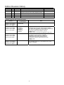
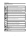
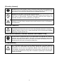
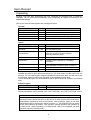
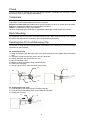


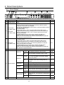


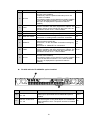

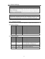
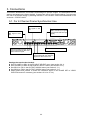
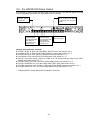
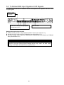
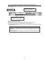

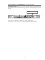
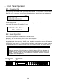
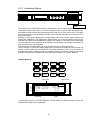

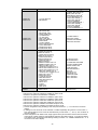
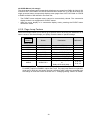
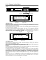

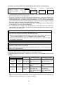

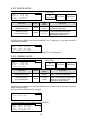


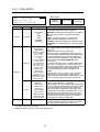

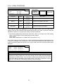
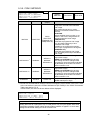
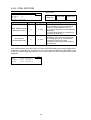
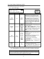
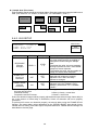


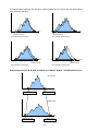
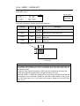

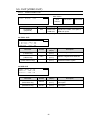
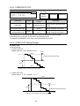
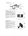

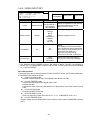
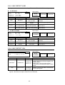

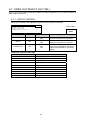

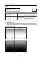

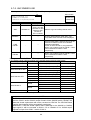


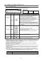


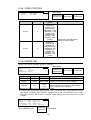
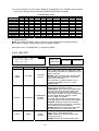
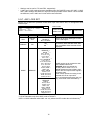
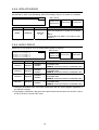
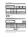
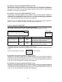
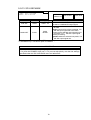

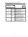
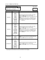
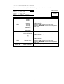

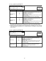
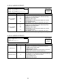
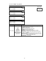
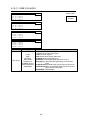
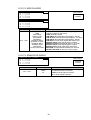
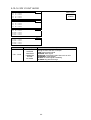
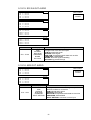

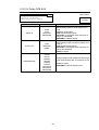

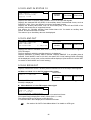

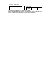
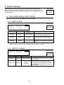
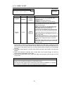
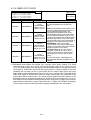

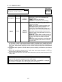

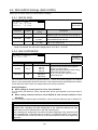
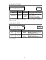
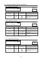
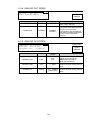
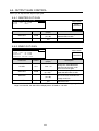
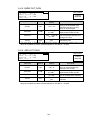


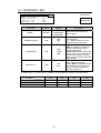


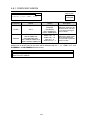

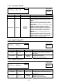
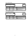

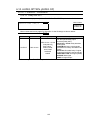
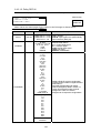
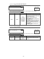
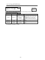
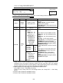
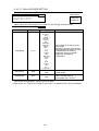
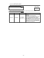

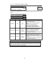
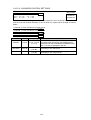
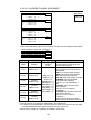
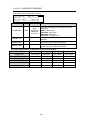

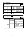
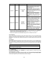
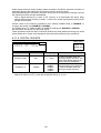
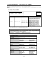
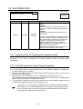

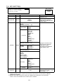

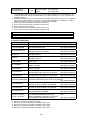
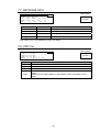
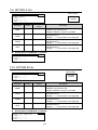
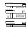
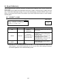
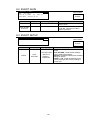
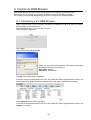
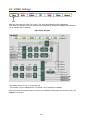

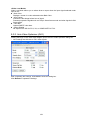
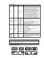
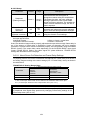
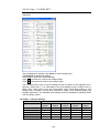
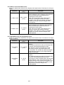
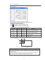

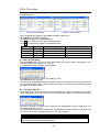
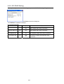
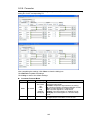


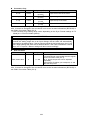

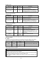
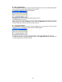
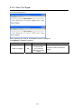
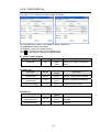
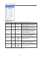
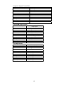
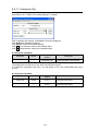
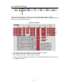

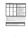
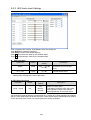

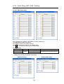


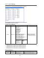
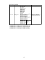
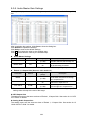

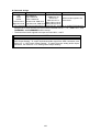
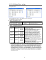
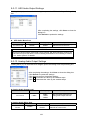
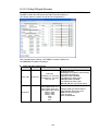
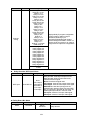
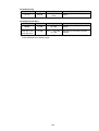


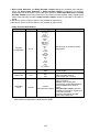
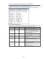
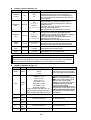
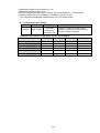


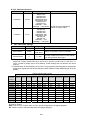
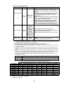
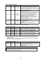
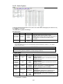
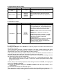

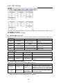
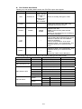
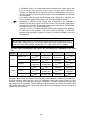


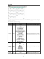

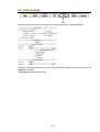


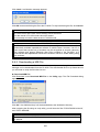


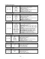
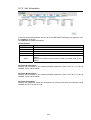
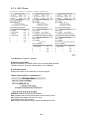


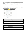

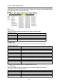
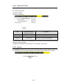
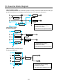
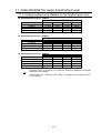
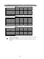
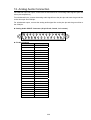
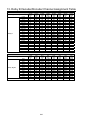
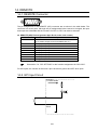
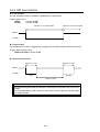
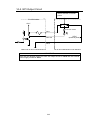
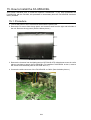
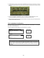
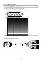

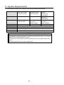
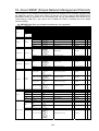
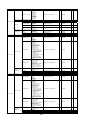
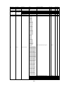


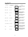
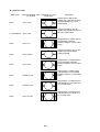
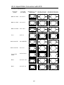

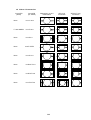
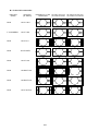
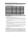

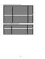

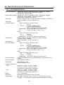
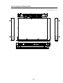


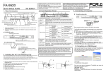
![FA-9500取扱説明書[PDF:5.7MB]](http://vs1.manualzilla.com/store/data/006598421_2-717a4c2dea34a9c29bc8082cc4713487-150x150.png)

![FA-9520セットアップガイド[PDF:380.1KB]](http://vs1.manualzilla.com/store/data/006554177_2-82b770087ef991f1d97021bb1b8b254b-150x150.png)


![FA-95LG取扱説明書[PDF:2.9MB]](http://vs1.manualzilla.com/store/data/006644661_3-b711ca06a712d12c50fc47387d88a410-150x150.png)
![FA-95RU取扱説明書[PDF:1.6MB]](http://vs1.manualzilla.com/store/data/006536810_2-6a88743f57f11a74b24ce589b01e0990-150x150.png)