1
OPERATION MANUAL FA-10DCCRU Remote Control Unit 2nd Edition – Rev. 1 Software Version 2.10 – Higher Edition Revision History Edit. 1 2 Rev. - Date 2014/06/30 2014/12/17 2 1 2015/05/29 Description 1st Edition Supported FA-505 units. Changed event save/load procedure. Changed default IP address to 192.168.0.101. Factual errors corrected 2 Section/Page 7 5-2, 5-6 Precautions Important Safety Warnings [Power] Operate unit only at the specified supply voltage. Caution Disconnect the power cord via the power plug only. Do not pull on the cable portion. Stop Do not place or drop heavy or sharp-edged objects on the power cord. A damaged cord can cause fire or electrical shock hazards. Regularly check the power cord for excessive wear or damage to avoid possible fire / electrical hazards. [Grounding] Ensure the unit is properly grounded at all times to prevent electrical shock. Caution Do not ground the unit to gas lines, units, or fixtures of an explosive or dangerous nature. Hazard Ensure the power cord is firmly plugged into the AC outlet. Caution [Operation] Do not operate the unit under hazardous or potentially explosive atmospheric conditions. Doing so could result in fire, explosion, or other hazardous results. Hazard Do not allow liquids, metal pieces, or other foreign materials to enter the unit. Doing so could result in fire, other hazards, or a unit malfunction. Hazard If a foreign material does enter the unit, turn the power off and immediately disconnect the power cord. Remove the material and contact an authorized service representative if damage has occurred. [Transportation] Caution Handle with care to avoid impact shock during transit, which may cause malfunction. When you need to transport the unit, use the original or suitable alternative packing material. 3 [Circuitry Access] Do not remove covers, panels, casing, or access the circuitry with power applied to the unit. Turn the power off and disconnect the power cord prior to removal. Internal servicing / adjustment of unit should only be performed by qualified personnel. Stop Do not touch any parts / circuitry with a high heat factor. Capacitors can retain enough electric charge to cause mild to serious shock, even after the power has been disconnected. Capacitors associated with the power supply are especially hazardous. Hazard Unit should not be operated or stored with cover, panels, and / or casing removed. Operating the unit with circuitry exposed could result in electric shock / fire hazards or a unit malfunction. [Potential Hazards] Caution If abnormal odors or noises are noticed coming from the unit, immediately turn the power off and disconnect the power cord to avoid potentially hazardous conditions. If problems similar to the above occur, contact an authorized service representative before attempting to operate the unit again. [Rack Mount Brackets, Ground Terminal, and Rubber Feet] Caution To rack-mount or ground the unit, or to install rubber feet, do not use screws or materials other than those supplied. Doing so may cause damage to the internal circuits or components of the unit. If you remove the rubber feet that are attached to the unit, do not reinsert the screws that secure the rubber feet. [Consumables] Caution Consumable items that are used in the unit must be periodically replaced. For further details on which parts are consumables and when they should be replaced, refer to the specifications at the end of the Operation Manual. Since the service life of the consumables varies greatly depending on the environment in which they are used, such items should be replaced at an early date. For details on replacing consumable items, contact your dealer. 4 Upon Receipt Unpacking FA-10DCCRU units and their accessories are fully inspected and adjusted prior to shipment. Operation can be performed immediately upon completing all required connections and operational settings. Check your received items against the packing lists below. Check to ensure no damage has occurred during shipment. If damage has occurred, or items are missing, inform your supplier immediately. ITEM FA-10DCCRU AC Cord Rack Mount Brackets QTY 1 1 set 1 set CD-ROM 1 Quick Setup Guide 1 REMARKS (Including an AC cord retaining clip) EIA standard type Installation Disc User manual (PDF) included Installing the AC Cord Retaining Clip Secure the AC cord with the supplied ladder strap/retaining clip assembly to prevent accidental removal from the unit. Installing the clip 1) Wrap the retaining clip around the AC cord. (with the anchor of the ladder strap toward the unit.) 2) Insert the anchor into the hole next to the AC IN socket. 3) Lightly fasten the clip around the AC cord. 4) Plug in the power cord. 5) Slide the clip on the ladder strap toward the plug. 6) Fasten the clip tightly. 7) Gently pull on the AC cord to ensure it is secured. 5) 6) 2) 4) 1) 2) 3) 3) Unpluging the AC cord Push the tab on the retaining clip up to unfasten the clip. Push the tab on the ladder strap up and slide the clip back. Unplug the AC cord. 1) 2) 5 Table of Contents 1. Prior to Starting ........................................................................................................................... 9 1-1. Welcome .............................................................................................................................. 9 1-2. Features ............................................................................................................................... 9 1-3. System Requirements for FA-10DCCRU Setup PC ............................................................ 9 2. Main Unit Compatibility ............................................................................................................. 10 2-1. FA-505 Compatibility .......................................................................................................... 10 2-2. FA-1010 Compatibility ........................................................................................................ 10 2-3. FA-9520 Compatibility ........................................................................................................ 10 2-4. FA-9500 Compatibility ........................................................................................................ 10 3. Panel Descriptions .................................................................................................................... 11 3-1. Front Panel ......................................................................................................................... 11 3-2. Rear Panel ......................................................................................................................... 13 4. Connecting to Main Units (FA-505/1010/9520/9500) ............................................................... 14 4-1. Basic Configuration ............................................................................................................ 14 4-2. Optional Configuration ....................................................................................................... 15 5. Setup ......................................................................................................................................... 16 5-1. Connecting an FA-10DCCRU to the Computer ................................................................. 16 5-2. Changing the FA-10DCCRU IP Address ........................................................................... 16 5-3. Web GUI............................................................................................................................. 18 5-3-1. Information .................................................................................................................. 18 5-3-2. Network Settings ......................................................................................................... 18 5-3-3. User Account Settings ................................................................................................ 19 5-3-4. Unit ID Assignment ..................................................................................................... 20 5-3-5. Direct Mode Settings................................................................................................... 21 5-3-6. Event Naming ............................................................................................................. 22 5-3-7. Backup & Restore ....................................................................................................... 23 5-3-8. System Restart ........................................................................................................... 25 6. Controlling FA-505/FA-1010/FA-9520/FA-9500 units............................................................... 26 6-1. Selecting Main Units .......................................................................................................... 26 6-1-1. Connecting a Main Unit in Unit Mode ......................................................................... 26 6-1-2. Connecting a Main Unit in Direct Mode ...................................................................... 27 6-1-3. Selecting the Connection Mode .................................................................................. 28 6-2. BYPS/OP (Bypass/Operate) .............................................................................................. 28 6-3. Selecting an FS Channel ................................................................................................... 28 6-4. Freeze Setting .................................................................................................................... 29 6-5. Split Display ....................................................................................................................... 29 6-6. UNITY Settings and Indicators........................................................................................... 30 6-7. UNITY Button and Unity Mode........................................................................................... 30 6-8. Process Control (Proc Amp) .............................................................................................. 31 6-9. Color Correction ................................................................................................................. 32 6-10. Clipping Signal Levels ...................................................................................................... 33 6-10-1. YPbPr Clip................................................................................................................. 34 6-10-2. RGB Clip ................................................................................................................... 36 6-11. Verifying Settings ............................................................................................................. 38 6 6-11-1. When in Color Correction Mode............................................................................... 38 6-11-2. When in Clip Mode ................................................................................................... 38 7. Event Memory........................................................................................................................... 39 7-1. About Event Memory ......................................................................................................... 39 7-2. Data Stored in Events ....................................................................................................... 39 7-3. Data Loaded from Events ................................................................................................. 39 7-4. Saving Settings to Events ................................................................................................. 40 7-5. Loading Settings from Events ........................................................................................... 40 8. SYSTEM Settings ..................................................................................................................... 41 8-1. System Settings ................................................................................................................ 42 8-2. GPI OUT LED Indicator Brightness Settings .................................................................... 43 9. Information Display ................................................................................................................... 44 9-1. Messages during Main Unit Connection ........................................................................... 44 9-2. Messages during Bypass Setting ...................................................................................... 45 9-3. Messages during FS Selection ......................................................................................... 45 9-4. Messages during Event Memory Operation ..................................................................... 46 9-5. Messages during Freeze Setting ...................................................................................... 46 9-6. Messages during Split Setting........................................................................................... 47 9-7. Messages during Proc Amp Settings ................................................................................ 47 9-8. Messages during Color Correction Settings ..................................................................... 48 9-9. Messages during Video Clip Settings ............................................................................... 49 9-10. Messages during System Settings .................................................................................. 50 10. GPI Interface .......................................................................................................................... 51 10-1. FA-GPIO Editor ............................................................................................................... 51 10-1-1. Installing the FA GPIO Editor ................................................................................... 51 10-2. About the FA GPIO Editor ............................................................................................... 54 10-2-1. Connecting FA GPIO Editor to the FA-10DCCRU................................................... 54 10-2-2. Loading and Assigning GPI Functions..................................................................... 56 10-2-3. GPI Input Settings .................................................................................................... 57 10-2-4. GPI Output Settings ................................................................................................. 59 10-2-5. Inverting GPI Output Pulse Polarity ......................................................................... 60 10-2-6. Sending GPI Settings ............................................................................................... 60 10-2-7. Pattern Load ............................................................................................................. 60 10-2-8. Exporting GPI Settings to Files ................................................................................ 61 10-2-9. Importing GPI Settings from Files ............................................................................ 61 10-2-10. Verifying GPIO Editor Version ............................................................................... 61 10-3. GPI Pattern List ............................................................................................................... 62 10-4. GPI1-GPI3 Pin Assignments ........................................................................................... 64 10-5. GPI Input Circuit .............................................................................................................. 65 10-6. GPI Input Control............................................................................................................. 65 10-7. GPI Output Circuit (Same for GPI 1-3) ........................................................................... 66 11. FS Link.................................................................................................................................... 67 11-1. Requirements for FS Link ............................................................................................... 67 11-2. Notes on FS Link ............................................................................................................. 67 11-3. FS Link Examples ........................................................................................................... 67 12. Resetting to Factory Default Settings..................................................................................... 68 7 13. Specifications and Dimensions ............................................................................................... 69 13-1. Unit Specifications............................................................................................................ 69 13-2. External Dimensions ........................................................................................................ 69 8 1. Prior to Starting 1-1. Welcome Congratulations! By purchasing an FA-10DCCRU Remote Control Unit you have entered the world of FOR-A and its many innovative products. Thank you for your patronage and we hope you will turn to FOR-A products again and again to satisfy your video and audio needs. FOR-A provides a wide range of products, from basic support units to complex system controllers, which have been increasingly joined by products for computer video-based systems. Whatever your needs, talk to your FOR-A representative. We will do our best to be of continuing service to you. 1-2. Features The FA-10DCCRU is a dedicated remote control unit for color correction, which can control FA-505, FA-1010, FA-9520 and FA-9500 units. Control of up to 100 FA-505 / FA-1010 / FA-9520 / FA-9500 units via Ethernet. Coexist with FA-10RU and FA-95RU in a system. Direct operation with 14 rotary encoders FA-505 / FA-1010 / FA-9520 / FA-9500 can accept up to 5 FA-10DCCRU control units simultaneously. Save up to 100 sets of settings in FA-10DCCRU GPI 30 inputs and 30 outputs Expansion control panel: FA-AUX30 (option) Windows-based GPIO utility: FA GPIO Editor 1-3. System Requirements for FA-10DCCRU Setup PC Item CPU Memory OS Free disk space Interface Web browser (*1) Display Recommended Intel Core i3, 1.2 GHz or faster 2 GB or more Windows 7/8 (32-bit / 64-bit), .NET Framework 4 or higher 1 MB or more Ethernet x 1 port Internet Explorer® 10 Firefox 29 or higher (JavaScript must be enabled.) 1024 x 768 (XGA) or better, 24-bit or 32-bit full-color 9 2. Main Unit Compatibility FA-10DCCRU units do not support all FA-505, FA-1010, FA-9520 or FA-9500 versions. Refer to the tables below for compatibility details. Main units with earlier software versions are unable to be (or to be fully) controlled by FA-10DCCRU units. Upgrade your main unit if it is fully or partially incompatible with the FA-10DCCRU. 2-1. FA-505 Compatibility FA-10DCCRU has no function restrictions depending on the FA-505 version. 2-2. FA-1010 Compatibility The table below shows information on FA-1010 / FA-10DCCRU compatibility. FA-1010 Software Ver. 1.00 - 2.01 FA-1010 Software Ver. 2.22 FA-1010 Software Ver. 3.00 or higher Unable to connect with FA-10DCCRU. Able to be controlled, with the following functions unavailable: BY-PASS/OPERATE Y Level SPLIT Able to be fully controlled by FA-10DCCRU. Refer to the FA-1010 Operation Manual for details on software version verification. 2-3. FA-9520 Compatibility The table below shows information on FA-9520 / FA-10DCCRU compatibility. FA-9520 mode Software Ver. 1.00 - 2.01 FA-9500 mode Software Ver. 7.00 - 8.01 FA-9520 mode Software Ver. 2.02 or higher FA-9500 mode Software Ver. 8.02 or higher Unable to connect with FA-10DCCRU. Able to be controlled, with the following functions unavailable: BY-PASS/OPERATE Y Level SPLIT Refer to the FA-9520 Operation Manual for details on software version verification. 2-4. FA-9500 Compatibility The table below shows information on FA-9500 / FA-10DCCRU compatibility. Soft Version 1.00 - 8.00 Soft Version 8.01 or higher Unable to connect with FA-10DCCRU. Able to be controlled, with the following functions unavailable: BY-PASS/OPERATE Y Level SPLIT Refer to the FA-9500 Operation Manual for details on software version verification. 10 3. Panel Descriptions 3-1. Front Panel (5) MEMORY/SET 1-5 (1) (2) 6-10 11-15/UNIT 16-20 BYPS/OP FS SEL 1 2 SELECT 3 - 4 5 6 (1) VIDEO LEVEL Y LEVEL C LEVEL SAVE LOAD CLEAR WHITE LEVEL SETUP/BLACK HUE R UNITY UNITY UNITY UNITY UNITY (10) (2) (3) FS SEL (4) MEMORY/SET (5) PROCESS CONTROL (6) GROUP ADJ SYSTEM (7) WHITE LEVEL (8) BLACK LEVEL BLACK LEVEL B R UNITY UNITY UNITY (11) Name BYPS/OP (BYPASS / OPERATE) G (9) G B R GAMMA G (12) UNITY UNITY UNITY UNITY FA-10DCCRU WHITE BAL CENTER DIF BLACK SEPIA B GRP ADJ SYSTEM SPLIT UNITY 1-5, 6-10, 11-15/UNIT, 16-20 (8) CLIP + (3) No. 7 (7) PROCESS CONTROL FREEZE 0 (6) UNITY (13) Description Main Unit selection buttons. Before selecting Main Unit ID numbers with these buttons, assign Main Units (FA-505, FA-1010, FA-9520 and FA-9500) to Unit ID numbers using IP addresses. See section 5-3-4. “Unit ID Assignment” and section 5-3-5. “Direct Mode Settings” for more details. Two connection modes are available: Direct and Unit. See section 6-1. “Selecting Main Units.” Allows you to select the operation mode by pressing the button. Performs the correction and outputs the corrected Lit signal. (Operate mode) Outputs the input signal without performing color Flashing correction (Bypass mode) Allows you to select an FS for which to adjust color correction settings when connecting to an FA-505, FA-1010 or FA-9520 (in FA-9520 mode). The button is disabled when connecting to an FA-9520 from FA-9500 or FA-9500 unit. See section 6-3. “Selecting an FS Channel.” Holding down the button allows you to select the Connection mode between Direct and Unit. See section 6-1-3. “Selecting the Connection Mode.” Allows you to save settings to / load settings from memory as needed. See section 7. “How to Use Event Memory.” Setting values are displayed while saving or loading settings. See section 9. “Information Display.” Allows you to adjust Proc Amp settings in Color Correction mode (with CLIP (10) unlit). See section 6-8. “Process Control” and section 6-9. “Color Correction.” Allows you to clip signal levels in Clip mode (with CLIP (10) lit) using the three center buttons. See section 6-10. “Clipping Signal Levels.” The settings apply to the selected FS if controlling an FA-505, FA-1010 or FA-9520 in FA-9520 mode. Allows you to adjust R, G, and B component levels (White, Black or Gamma) all together. While the button is lit, R, G and B component levels can be set together by turning the R, G or B control button. When holding down the button, the button blinks and the menu changes to SYSTEM settings mode. See section 8. “System Settings.” Allows you to adjust the white level. This setting is disabled in Sepia mode. The level adjustment applies to the selected FS if controlling an FA-505, FA-1010 or FA-9520 in FA-9520 mode. Allows you to adjust the black level. This setting is disabled in Sepia mode. The level adjustment applies to the selected FS if controlling an FA-505, FA-1010 or FA-9520 in FA-9520 mode. 11 No. (9) Name GAMMA LEVEL FREEZE (10) CLIP SPLIT (*1) Description Allows you to adjust the gamma level. In Sepia mode, only Y signal can be adjusted using the G control button. The level adjustment applies to the selected FS if controlling an FA-505, FA-1010 or FA-9520 in FA-9520 mode. Allows you to toggle Freeze On or Off. The button turns on while the video is frozen. See section 6-4. “Freeze Setting.” The setting applies to the selected FS if controlling an FA-505, FA-1010 or FA-9520 in FA-9520 mode. Allows you to toggle the mode between Color Correction and Clip. Holding down the buttons simultaneously changes the mode to Clip. See section 6-10. ” Clipping Signal Levels.” The setting applies to the selected FS if controlling an FA-505, FA-1010 or FA-9520 in FA-9520 mode. Allows you to change the video display mode in the following order: OFF > MODE1 > MODE2 > MODE3. The setting applies to the selected FS (by FS SEL) in an FA-1010. Pressing the UNITY button resets the value to default. Pressing the button again returns the default value to the previous value. (11) UNITY (*2) (12) WHITE/ CENTER/ BLACK Selects a gamma curve from WHITE, CENTER or BLACK. The setting applies to the selected FS if controlling an FA-505, FA-1010 or FA-9520 in FA-9520 mode. BAL/DIF/SEPIA Selects a correction type for Color Correction mode from the following: BAL (Balanced, mainly used for RGB signals) DIF (Differential, mainly used for YPbPr signals) SEPIA (Sepia color) The setting applies to the selected FS if controlling an FA-505, FA-1010 or FA-9520 in FA-9520 mode. (13) (*1) Split control is available if the FA-1010 software version is 3.00 or higher. Split control is not available for FA-9520 or FA9500. (*2) Two operation modes, Linked Unity and Unlinked Unity, are available for setting WHITE LEVEL, BLACK LEVEL and GAMMA LEVEL using the R, G and B UNITY buttons. See section 8. “SYSTEM Settings” and Section 6-7. “UNITY Button and Unity Mode” for more details. 12 3-2. Rear Panel (6) POWER GPI1 GPI2 ON GPI3 OFF (10/100/1000BASE-T) (2) (1)( 4) No. Name (3) (4) AC100-240V 50/60Hz IN TO MU (5) Description Used to connect to an FA-505, FA-1010, FA-9520 or FA-9500 via LAN. Set the unique IP address and connect to the network. Used to connect an FA-AUX30 or external expansion switch panel(s). To assign GPI functions, install the FA GPIO Editor software using the supplied CD-ROM. See section 10. “GPI Interface” for details on GPI connectors. Used to air cool the unit to prevent overheating. Do not block the ventilation openings. Used to ground the unit to protect operators against static electricity and / or electrical shock. (1) TO MU (2) GPI1 to GPI3 (3) Cooling Fan (4) Ground Terminal (5) AC cord retaining clip anchor hole Used to anchor the AC cord retaining clip. (6) AC IN Used for connection to an AC power source via the supplied accessory cord. (AC 100V-240V 50/60Hz) 13 4. Connecting to Main Units (FA-505/1010/9520/9500) Connect FA-10DCCRU units to main units (FA-505, FA-1010, FA-9520 and FA-9500) via Ethernet. FA-10RU and FA-95RU units can be connected in the same network. 4-1. Basic Configuration FA-1010 FA-10DCCRU SDI IN 1 DC POWER 1 GENLOCK 2 3 4 5 FA- 1010 OPTION SLOT 6 7 8 9 10 BY-PASS DC POWER 2 A B MEMORY/SET 1-5 FRAME SYNCHRONIZER C VIDEO IN AUDIO AUDIO IN 6-10 LTC IN 11-15/UNIT 16-20 SDI IN 1 DC POWER 1 GENLOCK 2 3 4 5 7 8 9 10 A INSTALL VIDEO VIDEO IN AUDIO AUDIO IN B SDI IN 1 DC POWER 1 GENLOCK 2 3 4 5 7 8 9 10 VIDEO IN AUDIO AUDIO IN B 5 6 7 WHITE LEVEL VIDEO LEVEL Y LEVEL C LEVEL SETUP/BLACK HUE UNITY UNITY UNITY UNITY UNITY VIDEO LEVEL Y LEVEL C LEVEL SETUP/BLACK HUE UNITY UNITY UNITY UNITY UNITY BLACK LEVEL R G B R G B R GAMMA G B UNITY UNITY UNITY UNITY UNITY UNITY UNITY UNITY UNITY WHITE CLIP + 6-10 GRP ADJ SYSTEM SPLIT 1 2 3 SELECT 4 - 5 6 7 1-5 6-10 1 2 3 4 5 BLACK LEVEL G B R G B R GAMMA G B UNITY UNITY UNITY UNITY UNITY UNITY UNITY UNITY BAL FA-10DCCRU CENTER DIF BLACK SEPIA WHITE GRP ADJ SYSTEM SPLIT PROCESS CONTROL FREEZE 0 WHITE LEVEL R UNITY CLIP + SAVE LOAD CLEAR MEMORY/SET FA- 1010 FRAME SYNCHRONIZER C PROCESS CONTROL FREEZE 0 A INSTALL VIDEO 4 - MEMORY/SET 1-5 BYPS/OP FS SEL OPTION SLOT 6 BY-PASS DC POWER 2 3 FA- 1010 D 11-15/UNIT 16-20 LTC IN 2 SAVE LOAD CLEAR FRAME SYNCHRONIZER C INITIALIZATION FAN ALARM 1 SELECT BYPS/OP FS SEL OPTION SLOT 6 BY-PASS DC POWER 2 PROCESS CONTROL FREEZE 0 D INSTALL VIDEO INITIALIZATION FAN ALARM 6 7 WHITE LEVEL VIDEO LEVEL Y LEVEL C LEVEL SETUP/BLACK HUE UNITY UNITY UNITY UNITY UNITY BLACK LEVEL R G B R G B R GAMMA G B UNITY UNITY UNITY UNITY UNITY UNITY UNITY UNITY UNITY BAL FA-10DCCRU CENTER DIF BLACK SEPIA WHITE BAL FA-10DCCRU D 11-15/UNIT 16-20 BYPS/OP FS SEL SELECT - + SAVE LOAD CLEAR CLIP CENTER DIF BLACK SEPIA GRP ADJ SYSTEM SPLIT INITIALIZATION FAN ALARM LTC IN FA-9520 POWER PS1/LOCK ON VIDEOIN FANALARM AUDIOIN DCPOWER PS2/LOCK GENLOCL OFF EVENT FA-10RU PROCESS SDI AUDIO AE S AUDIO CONV1 ANALOG CONV2 MAST ER AVO MAPPING CLIP DELAY IN SEL DOWNMIX OUT SEL M OD E VIDEO OP VIDEO S YS AUDIO S YS C C ST AT US VIDEO AUDIO POWER DISPLAY H D / S D F R A M E S Y N C H R ON I Z E R F1 F2 F3 F4 UN ITY UN ITY UN ITY UN ITY FS SEL FS LINK VIDEO IN DISPLAY AREA REMOTE HD / SD POWER LOCK VIDEO IN AUDIO IN DC POWER BY-PASS GENLOCK EVENT LOCK VIDEO IN AUDIO IN DC POWER BY-PASS GENLOCK F3 F4 UNITY UNITY FA-9500 CONV2 MASTER IN SEL DOWNMIX OUT SEL MODE STATUS AUDIO SYS OTHER VIDEO AUDIO FRAME S YS N C H R O N IZ E R F1 F2 F3 F4 UNITY UNITY UNITY UNITY FA-9500 AES AUDIO CONV1 ANALOG CONV2 MASTER AVO MAPPING CLIP DELAY IN SEL DOWNMIX OUT SEL MODE VIDEO SYS STATUS AUDIO SYS OTHER VIDEO AUDIO PROCESS DISPLAY AREA HD / SD FRAME S YS N C H R O N IZ E R FA-9500 F1 F2 F3 F4 UNITY UNITY UNITY UNITY CC AES AUDIO CONV1 ANALOG CONV2 MASTER AVO MAPPING CLIP DELAY IN SEL DOWNMIX OUT SEL MODE VIDEO OP AUDIO OP VIDEO SYS STATUS AUDIO SYS OTHER SDI AUDIO F1 F2 F3 F4 REMOTE CC VIDEO OP AUDIO OP SDI AUDIO DISPLAY AREA FAN ALARM ON EVENT S YS N C H R O N IZ E R F2 UNITY PROCESS F1 F2 F3 F4 HD / SD POWER FRAME REMOTE OFF CONV1 ANALOG CLIP DELAY VIDEO SYS LOCK ON MU SELECT F2 F3 F4 UNITY UNITY UNITY VIDEO IN BY-PASS AUDIO IN FAN ALARM GENLOCK OFF F1 UNITY FAN ALARM ON OFF AES AUDIO AVO MAPPING VIDEO OP AUDIO OP SDI AUDIO F1 F2 F3 F4 F1 UNITY FA-10RU PROC EMB 5 INPUT AES 9 ANC ANALOG 2 CC SETUP CLIP 3 DWN MIX BY-PASS 4 MAPPING 6 CLN SW GAINI 7 OUTPUT DELAY 8 OPTION 0 STATUS VIDEO AUDIO 10SYSTEM FA-95RU PROCESS FAN ALARM AUDIO IN DC POWER GENLOCK EVENT 1 DISPLAY AREA BY-PASS REMOTE CONTROL UNIT OT HER POWER LOCK BY-PASS GENLOCK FAN ALARM TEST SIGNAL OFF EVENT AUDIO OP F A- 9520 FA-9500 POWER ON OFF MU SEL LOCK ON FREEZE DC POWER F1 F2 F3 F4 REMOTE CC EVENT PROCESS SDI AUDIO F1 F2 F3 F4 DISPLAY AREA REMOTE R E M O T E C O N T R O L U N IF T F1 F2 F3 F4 UNITY UNITY UNITY UNITY AVO MAPPING VIDEO OP AUDIO OP A-95RU C C AES AUDIO CLIP DELAY VIDEO SYS AUDIO SYS CONV1 ANALOG CONV2 MASTER IN SEL DOWNMIX OUT SEL MODE STATUS OTHER AUDIO VIDEO VIDEO AUDIO PC Network hub FA-10GUI (PC) Specify unique IP addresses for all devices connected to the network. See section 5-3-2. “Network Settings” for details on IP address settings. A single FA-505, FA-1010, FA-9520 or FA-9500 unit can be controlled by up to 5 remote FA-10DCCRU, FA-10RU and/or FA-95RU units. An attempted 6th connection will not be accepted. 14 4-2. Optional Configuration Connection with an FA-AUX30 option FA-AUX30 GPI1 GPI2 GPI3 Supplied FA-AUX30 cables x 3 FA-10DCCRU POWER GPI2 ON GPI3 OFF (10/100/1000BASE-T) AC100-240V 50/60Hz IN GPI1 TO MU Connection with a user-made switch box FS1 FS2 FS3 FS4 FS5 FS6 FS7 FS8 FS9 FS10 Connect to GPI1-GPI3 connector FA-10DCCRU POWER GPI1 GPI2 GPI3 ON OFF (10/100/1000BASE-T) * See section 10. “GPI Interface” for details on GPI connectors. 15 AC100-240V 50/60Hz IN TO MU 5. Setup 5-1. Connecting an FA-10DCCRU to the Computer (1) Connect the FA-10DCCRU and your PC. Set the IP address of the PC so that it appears on the same LAN subnet. For example, 192.168.0.1 as shown below. FA-10DCCRU POWER GPI1 GPI2 GPI3 ON OFF (10/100/1000BASE-T) AC100-240V 50/60Hz IN TO MU PC Ethernet hub IP address: 192.168.0.101 Subnet mask: 255.255.255.0 IP address: 192.168.0.1 Subnet mask: 255.255.255.0 (2) Launch your web browser on the PC. Microsoft Internet Explorer is used in this manual. Other web browsers are also supported. (3) Enter the IP address of the FA-10DCCRU (default: 192.168.0.101) in your browser’s address bar. (4) When the FA-10DCCRU connection is established, the Information page will appear. 5-2. Changing the FA-10DCCRU IP Address (1) In the left pane of the Web GUI, click Network Settings. (2) If a login dialog window as shown below appears, enter the following user name and password. Default User name and Password User name: fa10dccru Password: foranetwork 16 (3) The Network Settings page is displayed in the right pane. (4) Change the FA-10DCCRU IP address as needed. Set a unique IP address and subnet mask in the LAN. (5) Click Apply. (6) Wait at least 1 second then click Restart in the left pane to display the System Restart page. Click Restart in the right pane to restart the FA-10DCCRU. New network settings are applied after the restart. 17 5-3. Web GUI 5-3-1. Information Click Information in the left pane to display the Information page, in which Unit Information and Connection Status details of the FA-10DCCRU are displayed. FA-10DCCRU version, serial number and network setting details Main Unit information Click Refresh to refresh the page. 5-3-2. Network Settings In the left pane of the Web GUI, clicking Network Settings displays the Network Settings page in the right pane, in which FA-10DCCRU network settings are entered. After settings are complete, click Apply to apply them. Item IP Address Subnet Mask Default Gateway Default 192.168.0.101 255.255.255.0 Description Allows you to set the FA-10DCCRU IP address and subnet mask. Set a unique IP address and connect to a LAN network. This setting is not required. Set the Default Gateway address according to your network circumstances. IMPORTANT Network Settings are applied after the FA-10DCCRU restarts. See section 5-3-8. “System Restart.” 18 5-3-3. User Account Settings This page allows you to change user name and password settings by logging in through the Web GUI. (1) Click User Account Settings in the left pane. (2) Enter a user name (Alphanumeric, up to 15 characters). Enter a password (Alphanumeric, up to 15 characters). Re-enter the password. (3) Click Apply. (4) Wait at least 1 second, then click Restart in the left pane to display the System Restart page. Click Restart in the right pane to restart the FA-10DCCRU. The new network settings are applied after the restart. IMPORTANT User Account Settings are applied after the FA-10DCCRU restarts. See section 5-3-8. “System Restart.” Do not forget your user name or password. If you forget your user name or password, set the FA-10DCCRU back to factory default settings (see section 12. “Resetting to Factory Default Settings”) and reset your user name and password. 19 5-3-4. Unit ID Assignment Click Unit ID Assignment in the left pane to display the Unit ID Assignment page. This page allows you to assign Main Units to Unit ID numbers using IP addresses and unit names. When controlling multiple main units, unit names can help you identify units. Up to 100 units can be registered in the list. (1) Move the mouse over the desired Unit ID numbers at the top of the page to display the list. Then click on the ID numbers (Unit 1- 20 for example). (2) Enter an IP address (required) under the Unit ID number for each unit (FA-505, FA-1010, FA-9520 or FA-9500) as shown above. If a unit is not registered in the list, the message “No Assigned IP Address” will appear when trying to connect to the unit. (3) Enter a unit name (not required) under the Unit ID number. Units names must be alphanumeric and within 15 characters. Unit names are displayed on the FA-10DCCRU front panel while selecting a main unit or after connection is established. If a unit name is not specified, the IP address will be displayed instead of a unit name. Change the Port (TCP port number) setting only when another device than those below exists in the LAN and uses this port number: FA-505 / FA-50GUI / FA-1010 / FA-10GUI / FA-9520 / FA-9500 / FA-10RU / FA-95RU / FA-10DCCRU If a port number is changed, set the same number for all devices listed above. (4) After all settings are finished, click Apply. IMPORTANT Do not forget to click Apply. When the list display or menu page is changed without clicking Apply, the settings in the list are ignored and they will return to their previous settings. 20 5-3-5. Direct Mode Settings Click Direct Mode Settings in the left pane to display the Direct Mode Settings page. This page allows you to assign Main Units to MU1 to MU20, which are used for direct mode connections. Up to 20 MU units (MU 1 – MU 20) can be registered in the Direct Mode list, but they must be registered in the Unit ID list. (See the previous page). See section 6-1-2. “Connecting a Main Unit in Direct Mode” for details on the connection procedure. As factory default, Unit ID 1 to 20 are set to MU 1 to 20. If you need to change these assignments, follow the procedure below. (1) Change the Unit ID numbers for MU 1 to MU 5. Click the MU 1–5 button. (2) Change the Unit ID numbers for MU 6 to MU 10, then click the MU 2-10 button. Change other settings in the same way. (3) When all settings are finished, click Apply. Note that if another page is entered without clicking Apply, the settings are ignored. IMPORTANT Note that if an IP address is not set under the associated Unit ID number in the Unit Assignment page (see section 5-3-4), it cannot be accessed using the Unit ID or MU number. When connecting to main units using the 1-5, 6-10, 11-15 or 16-20 button in Direct mode, user names set in the Unit Assignment page are displayed. If user names are not set, IP addresses are displayed. Setting Unit ID to “0” in the Direct Mode Settings page disables the connection. Use “0,” as necessary. 21 5-3-6. Event Naming Click Event Naming in the left pane to display the Event Naming page. This page allows you to assign names to events. The default names are Event 1 to Event 100. To change event names, follow the procedure below. (1) Move the mouse over the desired event numbers at the top of the page to display the list. Then click on the event numbers (Event 1- 20 for example). (2) Type a new name (alphanumeric, within 15 characters) under each event. (3) Click Apply. IMPORTANT Do not forget to click Apply. When the list display or menu page is changed without clicking Apply, the settings in the list are ignored and the event names return to the their previous settings. 22 5-3-7. Backup & Restore Click Backup & Restore in the left pane to display the Backup & Restore page. This page allows you to perform the following backup and restoration tasks. Backup and restore Network Settings, Unit ID Assignment, Direct Mode Settings, and Event Name pages, and GPI and System settings. Backup and restore Event data (See sections 7-4 and 7-5.) Copy settings to another FA-10DCCRU unit. (See sections 7-2 and 7-3.) Backing Up All FA-10DCCRU Settings (excluding Event Data) Clicking Save in the Config Data area allows you to save all settings as shown below. (1) Click Save in the Config Data area to display the Download dialog. (2) Click Save in the dialog. (3) A Select Destination dialog will appear. Specify the destination folder and click Save. The FA-10DCCRU settings are automatically stored in the backup file named “fa10dccru.csv.” Change the file name as necessary. Restoring Settings To restore stored settings, proceed as follows. 23 (1) Check on the checkboxes in the Config Data area to select data. (2) Click Browse to select the backup file. (3) Click Load. A confirmation dialog will appear. Click OK to load the settings. To cancel the process, click Cancel. IMPORTANT After loading network settings, restart the FA-10DCCRU. (See section 5-3-8. “System Restart.” Saving Event Data This procedure allows you to save all event data (1 – 100) in a file. (1) Click Save in the Config Data area to display the Download dialog. (2) Click Save in the dialog. (3) Specify the destination folder and click Save. All event data are automatically stored in the file named fa10dccru_evt.1re. Change the file name as necessary. Restoring Event Data (1) Click the browse button in the Event Data area and select the event backup file. (2) Click Load. All event data stored in the file are loaded. IMPORTANT Note that once event data are loaded, all settings in the FA-10DCCRU are replaced. 24 5-3-8. System Restart (1) Click Restart in the left pane to display the System Restart page. (2) Click Restart in the right pane. (3) A confirmation dialog will appear. Click OK to restart the FA-10DCCRU. Note that the following settings require a system restart and that they are applied after the restart. Do not forget to restart the FA-10DCCRU. Network Settings (See section 5-3-2. “Network Settings.”) User name or password settings (See section 5-3-3. “User Account Settings.”) Network Settings from the Backup & Restore page (See section 5-3-6. “Backup & Restore.”) 25 6. Controlling FA-505/FA-1010/FA-9520/FA-9500 units 6-1. Selecting Main Units When connecting Main Units (FA-505, FA-1010, FA-9520 and FA-9500) from an FA-10DCCRU, the following two connection modes are available: Unit mode: Connects to Main Units using Unit ID numbers. Direct mode: Connects to Main Units using Direct Numbers (MU1 to MU20) (Default connection mode is Direct mode.) IMPORTANT When powered on, wait at least 1 second and a half before the connection is establishd. 6-1-1. Connecting a Main Unit in Unit Mode (1) Set connection mode to Unit. (See section 6-1-3. “Selecting the Connection Mode.”) (2) Press 11-15/UNIT . (3) Turn VIDEO LEVEL to select a Unit ID. (+ and - buttons also available. Pressing and holding these buttons scrolls selections.) The Unit ID number is displayed while a selection is being entered. About 2 seconds later when the selection is confirmed, the Unit Name or IP address will also be displayed in a scroll view. <Display examples> ID01: FA-1010 ID01: 192.168.0.10 (No Name) ID01: No Assigned IP Address When IP Address and User Name are set under Unit ID 01: When only IP Address is set under the Unit ID number: When nothing is set under Unit ID 01: FA-10DCCRU cannot connect to a unit using Unit ID 01. Set an IP address and User Name for this number. See section 5-3-4. “Unit ID Assignment.” If Disconnect is selected instead of a Unit ID number, this connection channel is disabled. (4) Press SELECT or 11-15/UNIT to start the connection. While connecting to a main unit, “Connecting(Unit)” is displayed. If the connection time is too short, the message may not appear. (3) (2) MEMORY/SET 1-5 6-10 11-15/UNIT 16-20 BYPS/OP FS SEL PROCESS CONTROL FREEZE 0 1 SELECT 2 3 - 4 5 6 7 + SAVE LOAD CLEAR VIDEO LEVEL To cancel the connection process, press CLEAR. 26 C LEVEL SETUP/BLUCK HUE CLIP GRP SYST SPLIT UNITY (4) Y LEVEL UNITY UNITY UNITY UNITY <Display Examples (after connection)> Connected: FA-1010 Connected: IP 192.168.0.10 When IP Address and User Name (FA-1010) are set under the Unit ID number : When only IP Address (192.168.0.10) is set under the Unit ID number: 6-1-2. Connecting a Main Unit in Direct Mode (1) Set the connection mode to Direct. (See section 6-1-3. “Selecting the Connection Mode.”) (2) Press a number button within the desired Unit ID sequence: 1-5, 6-10, 11/15/UNIT or 16-20. Scrolling through a sequence, press the associated button as many times as needed; for example, to connect to an FA-1010 with Direct ID 1, press 1-5 once, to connect to an FA-1010 with Direct ID 7, press 6-10 twice. (See “Selecting an MU ID” below.) Direct ID display MEMORY/SET 1-5 6-10 (2) 11-15/UNIT 16-20 PROCESS CONTROL FREEZE 0 1 2 SELECT BYPS/OP FS SEL 3 - 4 5 6 7 + SAVE LOAD CLEAR VIDEO LEVEL Y LEVEL C LEVEL SETUP/BLUCK UNITY UNITY UNITY UNITY CLIP SPLIT (3) While connecting to a main unit, “Connecting(Direct)” is displayed. If the connection time is too short, the message may not appear. To cancel the connection process, press CLEAR. The message “Please Choose Direct MU No” will then be displayed, and the number buttons will blink, allowing you to reselect a Direct ID number. <Display Examples (after connection)> Connected: FA-1010 Connected: IP 192.168.0.10(No Name) Disconnect When User Name is set for the connected main unit: When User Name is not set for the connected main unit: No main unit is connected: * See section 5-3-4. “Unit ID Assignment” for details on Unit Name settings. Selecting an MU ID To select a desired MU ID, press the button until the desired ID number is displayed. Every time each number button is pressed, the displayed number will scroll through in the following order. 1-5 button: 6-10 button: 11-15 button: 16-20 button: MU 1→2→…→5→1 MU 6→7→…→10→6 MU 11→12→…→15→11 MU 16→17→…→20→16 If an IP address is not registered for an MU ID number, the number will be skipped. See section 5-3-5. “Direct Mode Setting” for details on MU ID number settings. See section 5-3-4. “Unit ID Assignment” for details on main unit assignments. 27 6-1-3. Selecting the Connection Mode (1) Press and hold down the FS SEL button for about 3 seconds. (2) The current connection mode is displayed in a scroll view. (3) To change to “Direct Mode Connection,” press -. To change to “Unit Mode Connection,” press +. (4) Verify the selection on the display and press SELECT or FS SEL to confirm the selection. IMPORTANT If the connection mode is changed from Unit to Direct, the message “Please Choose Direct MU No” will appear and the number buttons will blink. Select a Direct ID number to connect to a main unit. 6-2. BYPS/OP (Bypass/Operate) Pressing the BYPS/OP button changes the Bypass/Operation mode: -Bypass mode: The button is flashing and FA-505 / FA-1010 Color Correction is bypassed. -Operate mode: The button is lit. This mode cannot be changed while adjusting Clip levels. (See section 6-10. “Clipping Signal Levels.”) * Bypass can be selected when the FA-1010 software version is 3.00 or higher. Bypass cannot be selected for the FA-9520 or FA-9500. 6-3. Selecting an FS Channel When connecting FA-505 units, an FS channel can be selected from FS1 to FS5. When connecting FA-1010 units, an FS channel can be selected from FS1 to FS10. When connecting an FA-9520 in FA-9520 mode, an FS can be selected between FS1 and FS2. When connecting an FA-9520 in FA-9500 mode, an FS cannot be selected. (1) Press FS SEL to turn on the button. The selected FS number is displayed. (2) Use - and + to change the FS for control. When connecting FA-505/FA-1010 units and FS names are registered, the selected FS is displayed by its name. (FS names are not displayed for FA-9520 units in FA-9520 mode.) Pressing and holding the - or + button scrolls selections. While selecting an FS, the name is displayed in short form such as “FS1.” About 2 seconds after a selection, the name will appear in long form such as “FA-1010 FS1.” * See “FA-1010 Operation Manual” for details on setting FS Names. * See “FA-505 Operation Manual” for details on setting FS Names. (2) MEMORY/SET 1-5 6-10 11-15/UNIT 16-20 BYPS/OP FS SEL PROCESS CONTROL FREEZE 0 1 SELECT 2 3 4 - 5 6 7 + SAVE LOAD CLEAR VIDEO LEVEL Y LEVEL C LEVEL SETUP/BLUCK CLIP GRP ADJ SYSTEM SPLIT UNITY UNITY UNITY UNITY (1) NOTE While controlling an FS (FS SEL lit), other settings than the FS selection are not displayed. To display other settings, press FS SEL to turn the button light off. 28 WH R HUE UNITY UNITY 6-4. Freeze Setting The Freeze setting is available only when Sync Mode is set to Frame in the main FA-505, FA-1010, FA-9520 or FA-9500 unit. (See the respective Operation Manuals for details on Sync Mode.) Pressing the FREEZE button turns Freeze On (button lit) or Off (button unlit) The “Freeze” function is applied to FS channels for FA-505, FA-1010 and FA-9520 (FA-9520 mode) units. The “Freeze” function is applied to main units for FA-9520 (FA-9500 mode) and FA-9500 units. NOTE Freeze is unable to be set while a main unit is being selected or when changing system settings. The Freeze setting do not appear when FS SEL is lit. 6-5. Split Display The mode switches every time the SPLIT button is pressed, in the following order: OFF > MODE1> MODE2> MODE3 OFF: Displays the image after correction. MODE1: Splits the screen vertically and displays images before and after correction. MODE2: Splits the screen horizontally and displays images before and after correction. MODE3: Displays the image before correction. MEMORY/SET 1-5 6-10 11-15/UNIT 16-20 BYPS/OP FS SEL PROCESS CONTROL FREEZE 0 1 SELECT 2 3 - 4 5 6 7 + SAVE LOAD CLEAR VIDEO LEVEL Y LEVEL C LEVEL WHITE LEVEL SETUP/BLACK HUE R G BLACK LEVEL B R G B R GAMMA G GRP ADJ SYSTEM SPLIT UNITY UNITY UNITY UNITY UNITY UNITY UNITY UNITY UNITY UNITY UNITY UNITY UNITY FA-10DCCRU WHITE BAL CENTER DIF BLACK SEPIA B CLIP UNITY Input video Corrected video MODE: OFF MODE: 1 MODE: 2 MODE: 3 * Split can be selected when the FA-1010 software version is 3.00 or higher. Split is unable to be set for FA-9520 or FA-9500. NOTE Split is unable to be set while in Bypass mode or when changing system settings. The Split setting do not appear when FS SEL is lit. 29 6-6. UNITY Settings and Indicators Three indicators on each level control button indicate level status as shown below A center indicator that is turned on indicates the level is set to UNITY. A left indicator that is turned on indicates the level is set to less than UNITY level. A right indicator that is turned on indicates the level is set to more than UNITY level. Pressing a UNITY button resets the associated value to default. Pressing the button again returns the default value to the previous value. An error alarm will sound when a higher or lower limit is exceeded. 6-7. UNITY Button and Unity Mode UNITY buttons have two operation modes: Unlinked Unity and Linked Unity. Unlinked Unity mode UNITY is applied only to the selected FS. Linked Unity mode UNITY is applied to all linked FS channels (FS Link On). * * See section 8. “SYSTEM Settings” for more details on setting UNITY mode. See section 11. “FS Link” for more details on FS Linking. 30 6-8. Process Control (Proc Amp) In this section, use the following parameters to perform Proc Amp adjustments. VIDEO LEVEL Y LEVEL Adjusts the video level. Adjusts the luminance level. C LEVEL * Y LEVEL can be adjusted when the FA-1010 software version is 3.00 or higher. Y LEVEL is unable to be adjusted for FA-9520 or FA-9500. Adjusts the CHROMA LEVEL. (Adjusts the sepia level in Sepia Mode.) Adjusts the SETUP/BLACK level. Adjusts the HUE. (Adjusts the SEPIA color in Sepia Mode.) SETUP/BLACK HUE IMPORTANT Proc Amp is disabled while in Bypass, MU Selection, Clip Setting or System Setting mode. Proc Amp settings do not appear when FS SEL is lit. Note that changes are applied to all linked FS channels (FS Link On) in FA-505, FA-1010 or FA-9520 (FA-9520 mode). See section 11. “FS Link” for more details. 31 6-9. Color Correction In order to enter the Color Correction settings, first you need to select a correction mode using the following three buttons: BAL (Balance) button: DIF (Differential) button: SEPIA button: LEVEL G ITY RGB mode Color Difference (YPbPr) mode Sepia mode BLACK LEVEL B UNITY R UNITY G UNITY B UNITY R UNITY GAMMA G UNITY FA-10DCCRU WHITE BAL CENTER DIF BLACK SEPIA B UNITY The following settings are available in Color Correction mode. WHITE LEVEL BLACK LEVEL GAMMA White Level setting using the R, G and B components. (Disabled in Sepia mode.) Black Level setting using the R, G and B components. (Disabled in Sepia mode.) Gamma Level setting using the R, G and B components. (Only Y signal is adjustable using G in Sepia mode.) Three gamma curves (White, Center and Black) are selectable. GROUP ADJ allows you to select between Group adjustment and Individual adjustment. When GROUP ADJ is turned off, R, G and B levels can be set individually. When GROUP ADJ is turned on, R, G and B levels can all be set together by changing R, G or B. IMPORTANT Color Correction is disabled while in Bypass, MU Selection, Clip Setting or System Setting mode. Color Correction settings are not displayed when FS SEL is lit. Note that changes are applied to all linked FS channels (FS Link On) in FA-505, FA-1010 or FA-9520 (FA-9520 mode). See section 11. “FS Link” for more details. 32 6-10. Clipping Signal Levels To enter clip settings, first, change the mode from Color Correction to Clip. In the following situations, Clip mode is unable to be selected: While in System Settings (GRP ADJ/SYSTEM is flashing) To enter Clip mode, press GRP ADJ/SYSTEM to exit the System setting mode. While Changing Connection Mode (FS SEL is flashing) To enter Clip mode, press SELECT or FS SEL to complete the change, or complete the connection process. While Selecting a Unit ID (11-15 UNIT is flashing) To enter Clip mode, complete the connection process. While in Bypass mode (BYPS/OP is flashing) To enter Clip mode, change the mode to Operate. IMPORTANT Clip settings are not displayed when FS SEL is lit. Note that changes are applied to all linked FS channels (FS Link On) in FA-505, FA-1010 or FA-9520 (FA-9520 mode). See section 11. “FS Link” for more details. See section 11. “FS Link” for more details. If Color Corrector is remotely set to Bypass by another remote unit (FA-10DCCRU or FA-10RU) or FA-10GUI, the system automatically exits CLIP mode. (1) Press CLIP for at least 3 seconds. (2) A beep will sound and the CLIP button will flash to indicate the mode has changed to Clip. Press and hold CLIP. MEMORY/SET 1-5 6-10 11-15/UNIT 16-20 BYPS/OP FS SEL PROCESS CONTROL FREEZE 0 1 SELECT 2 3 - 4 5 6 7 + SAVE LOAD CLEAR VIDEO LEVEL Y LEVEL C LEVEL SETUP/BLUCK HUE CLIP GRP ADJ SYSTEM SPLIT UNITY UNITY UNITY UNITY UNITY (3) After all clip settings are finished, press CLIP to return to the Color Correction mode. * To enter clip settings in another FS when connecting to an FA-505, FA-1010 or FA-9520 (FA-9520 mode) unit, press FS SEL to turn on the button light, then select an FS. Note that clip settings are applied to the selected FS while FS SEL is unlit. 33 6-10-1. YPbPr Clip (1) With CLIP flashing, press DIF on the right end of the front panel to enable YPbPr Clip. (To disable the function, press DIF again.) (2) The following process control settings are available. Y LEVEL C LEVEL SETUP/BLACK Y signal White clipping C signal White clipping Y signal Black clipping (3) Adjust the clip setting while viewing the three indicators above the controls and the value on the MEMORY/SET display panel. (See “Signal levels and level display” below.) Pressing the UNITY button below the value resets the clip value to the default. (4) Repeat steps (2) and (3) to enter additional adjustments. IMPORTANT Note that changes are applied to all linked FS channels (FS Link On) in an FA-505, FA-1010 or FA-9520 (FA-9520 mode). See section 11. “FS Link” for more details. Signal levels and level display The relationship between indicators, controls, and clip settings are as shown below. MEMORY/SET 1-5 6-10 PROCESS CONTROL FREEZE 0 11-15/UNIT 16-20 1 SELECT BYPS/OP FS SEL 2 3 - 4 5 6 7 + SAVE LOAD CLEAR VIDEO LEVEL Y LEVEL C LEVEL SETUP/BLUCK WHITE LEVEL R HUE G BLACK LEVEL B R G B R GAMMA G GRP ADJ SYSTEM SPLIT UNITY UNITY UNITY UNITY UNITY UNITY UNITY ① Y White Clip Level Setting range: 50% - 109% Default (UNITY): 109% UNITY UNITY UNITY UNITY UNITY UNITY FA-10DCCRU WHITE BAL CENTER DIF BLACK SEPIA B CLIP UNITY 109% 100% Y White Clip setting range 50% 50% 0% SMPTE 100% color bars when 100% white Button Setting A Y LEVEL B C Level indicators Lit orange Flashes at 109% (UNITY). Lit green Lit orange Flashes at 50% 34 Panel display 101% - 109% 100% 50% - 99% ② Y Black Clip Level Setting range: -7.5% - 50% Default (UNITY): -7.5% 100% 50% 50% Y Black Clip setting range 0% -7.5% SMPTE 100% color bars when 100% black Button Setting A SETUP/ BLACK B C Level indicators Lit orange. Flashes at -7% (UNITY) Lit green Lit orange. Flashes at 50%. Panel display -7.5% - -1% 0% 1% - 50% ③ C White Clip Level Setting range: 50% - 111% Default (UNITY): 111% 50% 50% C White Clip setting range 111% 100% 50% 0% SMPTE 100% color bars when color 700mVp-p Button Setting A C LEVEL B C Level indicators Lit orange. Flashes at 111% (UNITY) Lit green Lit orange. Flashes at 50%. 35 Panel display 101% - 111% 100% 50% - 99% 6-10-2. RGB Clip (1) With CLIP flashing, press BAL on the right end of the front panel to enable RGB Clip. (To disable, press BAL again.) (2) The following process control settings are available. Y LEVEL SETUP/BLACK White clipping of RGB signal Black clipping of RGB signal (3) Adjust the clip setting while viewing the three indicators above the controls and the value on the MEMORY/SET display panel. (See “Signal levels and level display” below.) Pressing the UNITY button below the value resets the clip value to default. (4) Repeat steps (2) and (3) to enter additional adjustments. Signal levels and level display The relationship between indicators, controls, and clip settings are as shown below. MEMORY/SET 1-5 6-10 PROCESS CONTROL FREEZE 0 11-15/UNIT 16-20 1 2 SELECT BYPS/OP FS SEL 3 - 4 5 6 7 + SAVE LOAD CLEAR VIDEO LEVEL Y LEVEL C LEVEL SETUP/BLUCK WHITE LEVEL R HUE G BLACK LEVEL B R G B R GAMMA G GRP ADJ SYSTEM SPLIT UNITY UNITY UNITY UNITY UNITY UNITY UNITY UNITY UNITY UNITY UNITY UNITY UNITY FA-10DCCRU WHITE BAL CENTER DIF BLACK SEPIA B CLIP UNITY ① RGB WHITE LEVEL (YLEVEL) Setting range: 50% - 300% Default (UNITY): 300% Button Setting A Y LEVEL B C Level indicators Lit orange. Flashes at 300% (UNITY) Lit green Lit orange. Flashes at 50%. Panel display 101% - 300% 100% 50% - 99% ② RGB BLACK LEVEL (SETUP/BLACK) Setting range: -200% - 50% Default (UNITY): -200% Button Setting A SETUP/ BLACK B C Level indicators Lit orange. Flashes at 200% (UNITY) Lit green Lit orange. Flashes at 50%. 36 Panel display -200% - -1% 0% 1% - 50% White Clip default value 300% White Clip setting range 100% 50% Black Clip setting range 0% -200% Black Clip default value RGB Clip IMPORTANT Note that changes are applied to all linked FS channels (FS Link On) in an FA-505, FA-1010 or FA-9520 (FA-9520 mode). See section 11. “FS Link” for more details. 37 6-11. Verifying Settings Repeatedly pressing the + (or - ) button displays settings one after another. Settings are not be displayed while FS SEL is lit. 6-11-1. When in Color Correction Mode When in BALANCE or DIFFERENTIAL Correction Mode, repeatedly pressing the + button displays settings one after another in the following order. Video Level→Y Level→C Level→Setup/Black→Hue→ White R Level→White G Level→White B Level→ Black R Level→Black G Level→Black B Level→ Gamma R Level→Gamma G Level→Gamma B Level * Pressing the - button displays settings in the reverse order. When in SEPIA Correction Mode, repeatedly pressing the + button displays settings one after another in the following order. Video Level→Y Level→Sepia Level→Setup/Black→Sepia Color→Gamma G Level * Pressing the - button displays settings in the reverse order. 6-11-2. When in Clip Mode Pressing + in RGB Clip mode (and with FS SEL unlit) displays the following settings. RGB White Clip→RGB Black Clip * Pressing the - button displays settings in the reverse order. Pressing + in YPbPr Clip mode (and with FS SEL unlit) displays settings in the following order. Y White Clip→Chroma Clip→Y Black Clip * Pressing the - button displays settings in the reverse order. IMPORTANT Repeatedly pressing the + (or - ) button displays settings one after another. When the end setting is reached, the display returns to the top item. If the control is turned while displaying settings using the + button, the changed setting is displayed. Pressing the + button after that displays the next setting of the setting displayed before the control is turned. Example: Pressing the + button and adjusting SETUP/BLACK while Y LEVEL (YL 100%) is displayed shows “SB 10%”. Pressing the + button after that displays “Hue 0 ゚.” The - button works in the same way but in the reverse direction. 38 7. Event Memory 7-1. About Event Memory Event Memory allows you to save FA-10DCCRU settings and load them when needed. EVENT MEMORY can store 100 (1-100) settings, which are saved in the FA-10DCCRU and cannot be used from main units. In the following situations, event operations are disabled: While selecting an FS for FA-505, FA-1010 or FA-9520 in FA9520 mode (FS SEL is lit) To enable event operation, press FS SEL to turn off the button light. While in System Settings (GRP ADJ/SYSTEM is flashing) To enable event operation, press GRP ADJ/SYSTEM to exit the System setting mode. While Changing Connection Mode (FS SEL is flashing) To enable event operation, press SELECT or FS SEL to complete the change, or complete the connection process. While Selecting a Unit ID (11-15 UNIT is flashing) To enable event operation, complete the connection process. 7-2. Data Stored in Events When connecting an FA-505, FA-1010 or FA-9520 (in FA9520 mode) The current FS settings are saved to events. When connecting an FA-9520 (in FA-9500 mode) or FA-9500 The FA-9520 or FA-9500 settings are saved to events. 7-3. Data Loaded from Events When connecting an FA-505, FA-1010 or FA-9520 (in FA9520 mode) Event data is loaded to the current FS. When connecting an FA-9520 (in FA-9500 mode) or FA-9500 Event data is loaded to the Main Unit. 39 7-4. Saving Settings to Events Once all setup settings are completed, save the settings to event memory using the following procedure. MEMORY/SET 1-5 6-10 11-15/UNIT 16-20 PROCESS CONTROL FREEZE 0 1 SELECT 2 3 - 4 5 6 7 VIDEO LEVEL Y LEVEL C LEVEL SETUP/BLUCK CLIP + (1) BYPS/OP FS SEL SAVE LOAD CLEAR GRP ADJ SYSTEM SPLIT UNITY (2) (4) R HUE UNITY UNITY UNITY (3) (1) When connecting to an FA-505, FA-1010 or FA-9520, select an FS. (2) Press SAVE. A beep will sound and an event number is displayed. The event memory number will appear. (To cancel the process, press CLEAR.) (3) If you need to change the event number, use + and - to select the desired number (Event1 - Event100) Press + and - to increase and decrease the number. Holding down + or - for several seconds quickly increases and decreases the number. Pressing UNITY of VIDEO LEVEL sets the number to Event1. (4) Press SAVE. A beep will sound and the current settings are saved to the selected event. IMPORTANT Note that the following settings are not saved to event memory but are stored in the FA-10DCCRU. -BYPASS/OPERATE -FREEZE -GRP ADJ -FS SEL -SPLIT 7-5. Loading Settings from Events Follow the instructions below to load settings. Note that the current settings will be lost after settings are loaded. (1) When connecting to an FA-505, FA-1010 or FA-9520, select an FS. (2) Press the LOAD button. A bleep sounds and the event memory number flashes. (To cancel the operation, press CLEAR.) (3) Select the memory number from Default, Event0 to Event100 using the + and - (or VIDEO LEVEL) buttons. Press + and - to increase and decrease the number. Holding down + or - for several seconds quickly increases and decreases the number. Pressing UNITY of VIDEO LEVEL sets to Default. (4) Press the LOAD button. After a beep, the data is loaded from the memory. 40 UNITY UNITY 8. SYSTEM Settings Press and hold the GRP ADJ/SYSTEM button to enter System Setting mode. The GRP ADJ/SYSTEM button flashes in this mode. Pressing the flashing GRP ADJ/SYSTEM button exits System Setting mode and the button functions as a Group ADJ On/Off. The SELECT button allows you to select a setting. Successively pressing the button scrolls setting items in the following order. When the end setting is reached, the display returns to the top item. ① Unity Mode: Unlinked ↓ ② Front Buzzer: Enable ↓ ③ GPI Buzzer: Enable ↓ ④ Display Mode: Full ↓ ⑤ Display BRIGHT: 30% ↓ ⑥ GPI 1 No.1-10 ↓ ⑦ GPI 2 No.11-20 ↓ ⑧ GPI 3 No.21-30 ↓ ⑨IP: 192.168.0.101 ↓ ⑩ Subnet 255.255.255.0 ↓ ⑪ Gateway 0.0.0.0 ↓ ⑫ FAN: Normal ↓ ⑬ Soft Ver: 2.10 ↓ ⑭ FPGA1 Ver: 1.00 ↓ ⑮ FPGA2 Ver: 1.00 ↓ Unity Mode: Unlinked (Back to the top) IMPORTANT Note that in System Setting mode system settings can be checked and changed without a main unit connection. Other settings cannot be performed in this mode. 41 8-1. System Settings No. Menu item Setting buttons Description ① Unity Mode -, + buttons - Unlinked: UNITY is applied only to the relevant FS channel. + Linked: UNITY is applied to all linked FS channels. See section 11. “FS Link” for more details. ② Front Buzzer -, + buttons - Disable: Disables the front buzzer. + Enable: Enables the front buzzer. ③ GPI Buzzer -, + buttons - Disable: Disables the buzzer for GPI settings. + Enable: Disables the buzzer for GPI settings. ④ Display Mode -, + buttons - Full: Displays settings in detailed format. + Simple: Displays settings in short format. ⑤ Display BRIGHT -, + buttons Sets front panel brightness. Options are 1.7%, 3.3%, 5%, 6.7%, 8.3%, 11.7%, 15%, 18%, 23%, 30%(default), 37%, 47%, 60%, 80% and100% ⑥ GPI1 No.1-10 Rotary encoder (*1) Sets brightness for GPI OUT LED indicators (No1 – 10) from 0 to 255. (Default: 50) ⑦ GPI2 No.11-20 Rotary encoder (*1) Sets brightness for GPI OUT LED indicators (No11 – 20) from 0 to 255. (Default: 50) ⑧ GPI3 No.21-30 Rotary encoder (*1) Sets brightness for GPI OUT LED indicators (No21 – 30) from 0 to 255. (Default: 50) ⑨ IP: 192.168.0.101 (Display only) Displays the FA-10DCCRU IP address. ⑩ Subnet 255.255.255.0 (Display only) Displays the FA-10DCCRU subnet mask. ⑪ Gateway 0.0.0.0 (Display only) Displays the FA-10DCCRU default gateway. ⑫ FAN (*2) (Display only) Displays the FA-10DCCRU fan status. Normal: The fan is functioning normally. Stopped: The fan has stopped. ⑬ Software Ver: 2.00 (Display only) Displays the software version. ⑭ FPGA1 Ver: 1.00 (Display only) Displays the FPGA1 version. ⑮ FPGA2 Ver: 1.00 (Display only) Displays the FPGA2 version. (*1) See section 8-2. “GPI OUT LED Indicator Brightness Settings.” (*2) When the fan has stopped, turn off the unit power, notify your FOR-A reseller or supplier and change the fan. 42 8-2. GPI OUT LED Indicator Brightness Settings GPI OUT No. Controller GPI- OUT 1 GPI- OUT 2 GPI- OUT 3 GPI- OUT 4 GPI- OUT 5 GPI- OUT 6 GPI- OUT 7 GPI- OUT 8 GPI- OUT 9 GPI- OUT 10 GPI- OUT 11 GPI- OUT 12 GPI- OUT 13 GPI- OUT 14 GPI- OUT 15 GPI- OUT 16 GPI- OUT 17 GPI- OUT 18 GPI- OUT 19 GPI- OUT 20 GPI- OUT 21 GPI- OUT 21 GPI- OUT 23 GPI- OUT 24 GPI- OUT 25 GPI- OUT 26 GPI- OUT 27 GPI- OUT 28 GPI- OUT 29 GPI- OUT 30 VIDEO LEVEL Y LEVEL C LEVEL SETUP/BLACK HUE WHITE LEVEL R WHITE LEVEL G WHITE LEVEL B BLACK LEVEL R BLACK LEVEL G VIDEO LEVEL Y LEVEL C LEVEL SETUP/BLACK HUE WHITE LEVEL R WHITE LEVEL G WHITE LEVEL B BLACK LEVEL R BLACK LEVEL G VIDEO LEVEL Y LEVEL C LEVEL SETUP/BLACK HUE WHITE LEVEL R WHITE LEVEL G WHITE LEVEL B BLACK LEVEL R BLACK LEVEL G System menu item (GPI connector) FA-AUX30 block ⑦ GPI1 No.1-10 (GPI1) Left block ⑧ GPI2 No.11-20 (GPI2) Center block ⑨ GPI3No.21-30 (GPI3) Right block * See section 10-4. “GPI1-GPI3 Pin Assignments.“ 43 9. Information Display While setting up the FA-10DCCRU, relevant information is displayed on the 8-digit display in two modes (Full and Simple). The following Information Display lists show when these information messages are displayed. Full: Displays information or message in detailed format. Note that while setting menu items, information is displayed in Simple mode and about 2 seconds after entering a setting, it is displayed in Full mode. Simple: Displays information or message in short format. * To change the display mode, set under ④ Display Mode (See section 8. “SYSTEM Settings.”) 9-1. Messages during Main Unit Connection (**: Setting values) Displayed message (Full / Simple) When information/message is displayed: Refer to Please Choose Direct MU No FA-10DCCRU is in Direct Connection mode, but no main unit is selected. Connect to a main unit using 1-5, 6-10, 11-15 or 16-20 button. 6-1-2 ID** When FA-10DCCRU is connected to a main unit in Unit ID Connection mode, its Unit ID number is displayed. 6-1-1 Disconnect FA-10DCCRU is in Unit ID Connection mode, but no main unit is connected. It is also displayed while trying to connect to a main unit. 6-1-1 6-1-2 ID**: No IP Address Assigned FA-10DCCRU is trying to connect to a main unit in Unit ID Connection mode, but no IP address has been set for the specified Unit ID number. 6-1-1 ID**: IP**. **. **. ** (No Name) When FA-10DCCRU is connected to a main unit in Unit ID Connection mode and no Unit Name is set for the main unit, its IP address is displayed. 6-1-1 ID**: FA-1010 When FA-10DCCRU is connected with a main unit, its Unit Name is displayed. 6-1-1 Direct Mode Connection While changing the connection mode to Direct. 6-1-2 Unit Mode Connection While changing the connection mode to Unit ID. 6-1-1 No Assigned IP Address FA-10DCCRU is trying to connect to a main unit in Direct Connection mode by pressing a number button (1-5, 6-10, 11-15 or 16-20), but no IP address has been set for the specified MU ID number. Set an IP address for the MU ID (Unit ID) number. 6-1-1 Connecting(Direct) FA-10DCCRU is connecting to a main unit in Direct Connection mode. If the connection time is too short, the message may not appear. 6-1-1 Connecting (Unit) FA-10DCCRU is connecting to a main unit in Unit ID Connection mode. If connection time is too short, the message may not appear. 6-1-2 No Connection Established (IP **. **. **. **) When the FA-10DCCRU fails to connect to a main unit, the message and specified main unit IP address are displayed. Verify the network connection and settings. Note that the FA-10DCCRU will attempt to connect to the main unit while the message is being displayed. 6-1 44 When information/message is displayed: Refer to Over Limit (IP **. **. **. **) When FA-10DCCRU is attempting to connect to a main unit, the main unit has connected with 5 remote control units (maximum) and this connection fails. To connect to the main unit, the main unit must disconnect one of the connected remote control units. This message may also be displayed when a disconnection is being improperly performed. Note that it will take 1 minute at most to complete the disconnection process. 6-1 Connected: IP **.**.**.**(No Name) When FA-10DCCRU is connected to a main unit in Direct Connection mode and no Unit Name is set for the main unit, its IP address is displayed. The message is cleared when there is no operation within 1 minute. Connected: FA-1010 When FA-10DCCRU is connected to a main unit in Direct Connection mode, the message is displayed with its Unit Name (FA-1010) for about 7 seconds. 6-1 MU is Local Mode When the FA-10DCCRU is connected to a main unit, but the main unit operates in local mode, this message will appear and the main unit cannot be controlled from the FA-10DCCRU. To control the main unit, change the operation mode to Remote in the main unit. - Displayed message (Full / Simple) 9-2. Messages during Bypass Setting When information/message is displayed: Displayed message (Full / Simple) Refer to By-pass Displayed when the connected FA-505/FA-1010 is set to Bypass. 6-2 Operate (*1) Displayed when the connected FA-505/FA-1010 is set to Operate. 6-2 By-pass No Support (*1) Displayed when trying to set to Bypass for the main unit that has no bypass function. 2 6-2 (*1) The display is automatically turned off when there is no operation within 1 minute. 9-3. Messages during FS Selection Displayed message (Simple) When information/message is displayed: Refer to FS* (Same as in Full mode) FS number of connected FA-9520 (9520 mode). 6-3 FS*: FS1 Name FS* FS number and FS Name (FS1 Name) of connected FA-505/ FA-1010. 6-3 FS*(No Name) FS* FS number (without FS Name) of connected FA-1010. See the FA-505/FA-1010 Operation Manual for details on how to assign names to FSs. 6-3 FS Select No Support (Same as in Full mode) Displayed when attempting to select an FS for an FA-9520 (FA-9500 mode) or FA-9500. The display is automatically turned off when there is no operation within 1 minute. 2 6-3 Displayed message (Full) 45 9-4. Messages during Event Memory Operation Displayed message (Full) Displayed message (Simple) When information/message is displayed: Refer to Default Default Displayed when default settings are being loaded. 7-3 Load **: Event1 Load ** Event number and name (Event1 in this example) displayed when loading an event. 5-3-6 7-3 Load **(No Name) Load ** Event number (with no name) displayed when loading an event. 5-3-6 7-3 Loading (Same as in Full mode) Displayed while loading events. 7-3 Loaded Default (*1) (Same as in Full mode) Displayed when an event with default settings has been loaded. 7-3 Loaded Event** (*1) (Same as in Full mode) Displayed when an event with no name has been loaded. 5-3-6 7-3 Loaded Event**: Event1 (*1) (Same as in Full mode) Displayed when a named event (Event1) has been loaded. 5-3-6 7-3 Save **: Event1 Save ** Event number and name (Event1) displayed when saving settings to an event. 5-3-6 7-2 Save **(No Name) Save ** Event number (with no name) displayed when saving settings to an event. 5-3-6 7-2 Saving (Same as in Full mode) Displayed while saving settings to events. 7-2 Saved Event** (*1) (Same as in Full mode) Displayed when settings have been saved to an event with no name. 5-3-6 7-2 Saved Event**: Event1 (*1) (Same as in Full mode) Displayed when settings have been saved to a named event (Event1). 5-3-6 7-2 (*1) The display is automatically turned off when there is no operation within 1 minute. 9-5. Messages during Freeze Setting Displayed message (Full) Displayed message (Simple) When information/message is displayed: Refer to Freeze On (Same as in Full mode) Displayed when Freeze is set to On. 6-4 Freeze Off (Same as in Full mode) Displayed when Freeze is set to Off. 6-4 The display is automatically turned off when there is no operation within 1 minute. 46 9-6. Messages during Split Setting Displayed message (Full) Displayed message (Simple) When information/message is displayed: Refer to Split: Off Off Displayed when Split is set to Off. 6-5 Split: Mode1 Mode1 Displayed when Split is set to Mode1. 6-5 Split: Mode2 Mode2 Displayed when Split is set to Mode2. 6-5 Split: Mode3 Mode3 Displayed when Split is set to Mode3. 6-5 Split No Support (Same as in Full mode) Displayed when trying to set Split to a main unit that has no Split function. 2 6-5 The display is automatically turned off when there is no operation within 1 minute. 9-7. Messages during Proc Amp Settings In Full display mode, text in parentheses are displayed during menu settings. When verifying settings using - and + buttons, information is displayed in Simple display mode. Displayed message (Full) Displayed message (Simple) When information/message is displayed: Refer to Video Level: ***.*% (***.*%) VL ***% Displayed when the Video Level setting is changed. 6-8 Y Level: ***.*% (***.*%) YL ***% Displayed when the Y Level setting is changed. 6-8 Y Level No Support (Same as in Full mode) Displayed when trying to change the Y Level setting of a main unit with no Y Level parameters. 2 Chroma Level: ***.*% (***.*%) CL ***% Displayed when the Chroma Level setting is changed. 6-8 Setup/Black: ***.*% (***.*%) BL **% Displayed when the Setup/Black Level setting is changed. 6-8 Hue: *.*° (*.*°) Hue *° Displayed when Hue is changed. 6-8 The display is automatically turned off when there is no operation within 1 minute. When Color Correction mode is set to Sepia: Displayed message (Full) Displayed message (Simple) When information/message is displayed: Refer to Sepia Level : ***.*% (***.*%) SL ***% Displayed when the Sepia Level setting is changed. 6-8 6-9 Sepia Color: *.*° (***.*°) SC *° Displayed when the Sepia Color setting is changed. 6-8 6-9 The display is automatically turned off when there is no operation within 1 minute. 47 9-8. Messages during Color Correction Settings In Full display mode, text in parentheses are displayed during menu settings. When verifying settings using - and + buttons, information is displayed in Simple display mode. See section 6-9. “Color Correction” for more details. Displayed message (Full) Displayed message (Simple) When information/message is displayed: White R Level: ***.*% (***.*%) WR ***% Displayed when the White R Level setting is changed. White G Level: ***.*% (***.*%) WG ***% Displayed when the White G Level setting is changed. White B Level: ***.*% (***.*%) WB ***% Displayed when the White B Level setting is changed. Black R Level: ***.*% (***.*%) BR ***% Displayed when the Black R Level setting is changed. Black G Level: ***.*% (***.*%) BG ***% Displayed when the Black G Level setting is changed. Black B Level: ***.*% (***.*%) BB ***% Displayed when the Black B Level setting is changed. Gamma R Level: ***.*% (***.*%) GR ***% Displayed when the Gamma R Level setting is changed. Gamma G Level: ***.*% (***.*%) GG ***% Displayed when the Gamma G Level setting is changed. Gamma B Level: ***.*% (***.*%) GB ***% Displayed when the Gamma B Level setting is changed. The display is automatically turned off when there is no operation within 1 minute. In Full display mode, text in parentheses are displayed during menu settings. Displayed message (Full) Displayed message (Simple) When information/message is displayed: Curve White (White) White Displayed when Gamma Curve is set to White. Curve Center (Center) Center Displayed when Gamma Curve is set to Center. Curve black (Black) Black Displayed when Gamma Curve is set to Black. Balance (Same as in Full mode) Displayed when Color Correction Mode is set to Balance. Differential (DIF) DIF Displayed when Color Correction Mode is set to Differential. Sepia (Same as in Full mode) Displayed when Color Correction Mode is set to Sepia. The display is automatically turned off when there is no operation within 1 minute. 48 9-9. Messages during Video Clip Settings In Full display mode, text in parentheses are displayed during menu settings. When verifying settings using - and + buttons, information is displayed in Simple display mode. See section 6-10. “Clipping Signal Levels” for more details. Displayed message (Full) Displayed message (Simple) When information/message is displayed: Clip Off (Same as in Full mode) Displayed when Video Clip Mode is set to Off. RGB Clip (Same as in Full mode) Displayed when Video Clip Mode is set to RGB. YPbPr Clip (YPbPr) YPbPr Displayed when Video Clip Mode is set to YPbPr. RGB White Clip: ***.*% (***.*%) RW ***% Displayed when the RGB White Clip Level setting is changed. RGB Black Clip: ***.*% (***.*%) RB ***% Displayed when the RGB Black Clip Level setting is changed. Y White Clip: ***.*% (***.*%) YW ***% Displayed when the Y White Clip Level setting is changed in YPbPr mode. Y Black Clip: ***.*% (***.*%) YB ***% Displayed when the Y Black Clip Level setting is changed in YPbPr mode. Chroma Clip: ***.*% (***.*%) CW ***% Displayed when the Chroma Clip Level setting is changed in YPbPr mode. The display is automatically turned off when there is no operation within 1 minute. 49 9-10. Messages during System Settings Text in parentheses are displayed during menu settings. See section 8. “System Settings” for more details. Displayed message (Full / Simple) When information/message is displayed: Unity Mode: Unlinked Displayed while Unity Mode is being set to Unlinked. Unity Mode: Linked Displayed while Unity Mode is being set to Linked. Front Buzzer: Enable Displayed while Front Buzzer is being enabled. Front Buzzer: Disable Displayed while Front Buzzer is being disabled. GPI Buzzer: Enable Displayed while GPI Buzzer is being enabled. GPI Buzzer: Disable Displayed while GPI Buzzer is being disabled. Display Mode: Full Displayed while Display Mode is being set to Full. Display Mode: Simple Displayed while Display Mode is being set to Simple. Display BRIGHT: **% Displayed while Brightness is being changed. GPI1 No.1-10 Displayed when entering the GPI1 Brightness setting. GPI2 No.11-20 Displayed when entering the GPI2 Brightness setting. GPI3 No.21-30 Displayed when entering the GPI3 Brightness setting. GPI Port* BRIGHT: ** (No.* : **) Displayed while a GPI OUT LED Brightness is being changed. IP: **. **. **. ** IP address of FA-10DCCRU. Subnet: **. **. **. ** Subnet mask of FA-10DCCRU Gateway: **. **. **. ** Default gateway of FA-10DCCRU FAN: Normal Displayed when the FA-10DCCRU FAN is functioning normally. FAN: Stopped Displayed when the FA-10DCCRU FAN has stopped. Soft Ver: *. ** Software version of FA-10DCCRU FPGA1 Ver: *. ** FPGA1 version of FA-10DCCRU FPGA2 Ver: *. ** FPGA2 version of FA-10DCCRU Other Factory Setting Displayed when resetting to factory default settings. See section 12. ”Resetting to Factory Default Settings.” 50 10. GPI Interface GPI input /output functions can be assigned to GPI ports 1-30 (GPI 1-3 connectors) on the FA-10DCCRU using the supplied FA GPIO Editor software. GPI input and output functions can be assigned to ports individually or in 10-port groups. (See section 10-4.) GPI settings can be backed up to and restored from files using Export and Import. (See section -2) 10-1. FA-GPIO Editor 10-1-1. Installing the FA GPIO Editor Use the supplied CD-ROM to install the FA GPIO Editor software. Before installing this software, close all other applications on the computer. (1) Insert the supplied CD-ROM into the PC. Click “FA GPIO Editor > setup “ on the CD-ROM to start the installation wizard. (2) Click Next. (3) The Software License Agreement window appears. Read the agreement statement and check the I accept the terms in license agreement check box, then click next. To cancel the installation, click Cancel. 51 NOTE To print the Software License Agreement, click Print. Before printing the License agreement, verify that your printer is actually connected to the PC. (4) The installation directory of the FA GPIO Editor is displayed. To change the default installation directory, click Change… and specify a new directory. (5) Click Next. (6) The last wizard page is displayed. Verify the installation settings and click Install to install the software. To change settings, click on Back, change installation settings as required, then click Install. 52 (7) When the software installation is complete, the window as shown below will appear. Click Finish to finish the installation. 53 10-2. About the FA GPIO Editor GPI input /output functions can be assigned to 30 GPI ports (GPI 1-3 connectors) on the FA-10DCCRU using the supplied FA GPIO Editor software. GPI assignments are very flexible: an input or output or both can be assigned to a port, GPI pulse signals can be output inversely and assignments can be performed individually or in groups using Pattern Load. In addition, GPI settings can be backed up to and restored from files using Export and Import. 10-2-1. Connecting FA GPIO Editor to the FA-10DCCRU (1) Click the FA GPIO Editor shortcut icon on the desktop to start FA GPIO Editor. (2) When the software window appears, enter the FA-10DCCRU IP address, user name and password. Click Load. < Default FA-10DCCRU settings> IP address: 192.168.0.101 User name: fa10dccru Password: foranetwork 54 (3) When the user name and password are accepted, a window as shown below is displayed and FA-10DCCRU GPI settings are loaded in the window. When the user name and password are not accepted, the following pop-up dialog windows appears. Click OK to close the dialog. Enter the correct user name and password and click Load. 55 10-2-2. Loading and Assigning GPI Functions As factory default, GPI functions are all set to None (no function). Use the FA-GPIO Editor to perform GPI assignments for GPI1 - 3 (Ports 1-30) connectors. Select a GPI connector (10 ports) by clicking a tab from the following three: GPI Port 1 - 10(FA-AUX30 Left Block) GPI Port 11 - 20(FA-AUX30 Center Block) GPI Port 21 - 30(FA-AUX30 Right Block) Note that “(FA-AUX30…)” indicates a button block (seen from the front side) when connecting an FA-AUX30 unit. 56 10-2-3. GPI Input Settings A combination of GPI input settings (Setting 1, Setting 2 and Setting 3) can be assigned to each GPI port. GPI ports are activated when they are closed with a common port. (1) First, set Setting 1. To disable ports, set None under Setting 1. Detailed Input Settings Setting 1 setting None MU Select FS Select FS Link (toggled On/Off) Freeze (toggled On/Off) Split Mode CC Mode Gamma Curve Clip GPI Lock (toggled On/Off) Group Adjust (toggled On/Off) Event Load Event Save Description No function MU Select allows you to select a main unit under Setting 2 (Unit ID1 - 100) and an FS of the main unit under Setting 3 (FS1 - 10). If set to None under Setting 3, the last controlled FS is selected. Main unit IP addresses must be set for Unit ID numbers in advance. If set to Disconnect under Setting 2, the port can disconnect main units. FS Select allows you to select an FS under Setting 2, FS1 - FS10 if connecting to FS-1010 and FS1 or FS2 if connecting to FA -9520 (FA-9520 mode). FS Select is inoperative when connecting with FA-9520 (FA-9500 mode) or FA-9500 units. Allows you to link or unlink an FS under Setting 2. If All Clear is set under Setting 2, all FS channels are unlinked. Allows you to set Freeze to On or Off. If an FS is selected under Setting 2, the controlled FS is changed to the selected one and a Freeze setting is applied to it. If None is set under Setting 2, a Freeze setting applies to the current FS. Allows you to set Split mode under Setting 2. If an FS is selected under Setting 3, the controlled FS is changed to the selected one and a Split Mode setting is applied to it. If None is set under Setting 3, a Split Mode setting applies to the current FS. Allows you to set Color Correction mode under Setting 2. If an FS is selected under Setting 3, the controlled FS is changed to the selected one and a CC Mode setting is applied to it. If None is set under Setting 3, a CC Mode setting applies to the current FS. Allows you to set Gamma Curve under Setting 2. If an FS is selected under Setting 3, the controlled FS is changed to the selected one and a Gamma Curve setting is applied to it. If None is set under Setting 3, a Gamma Curve setting applies to the current FS. Allows you to set Clip mode under Setting 2. If an FS is selected under Setting 3, the controlled FS is changed to the selected one and a Clip setting is applied to it. If None is set under Setting 3, a Clip setting applies to the current FS. Allows you to enable (GPI Lock Off) / disable (GPI Lock On) all GPI inputs. Allows you to enable / disable group adjustment. The group adjustment functions are adjusted in the same manner as those in FA-10DCCRU. Allows you to load an event set under Setting 2 (Event1 - 100). Allows you to save settings to an event set under Setting 2 (Event1 - 100). 57 Refer to 5-3-4 - 11 6-4 6-5 6-9 6-9 6-10 6-9 7 7 (2) Set Setting 2 and Setting 3 according to Setting 1. Input Setting List Port No. Setting 1 None MU Select Setting 2 Disconnect Unit ID1 - 100 FS Select FS Link(On/Off) FS1 - FS10 All Clear FS1 - FS10 None FS1 - FS10 Off Mode1 - 3 Balance Differential Sepia Center Black White Off YPbPr RGB Default Event1 - 100 Event1 - 100 Freeze(On/Off) Split Mode CC Mode 1 - 30 Gamma Curve Clip GPI Lock(On/Off) Group Adjust(On/Off) Event Load Event Save 58 Setting 3 None FS1 - FS10 None FS1 - FS10 None FS1 - FS10 None FS1 - FS10 None FS1 - FS10 - 10-2-4. GPI Output Settings Available GPI output functions are shown below. Output Setting List Port No. Function None Follow GPI In Settings All DC/FAN Alarm (*1) FA-10DCCRU FAN Alarm MU/FA-10DCCRU FAN Alarm MU FAN1 Alarm MU FAN2 Alarm MU FAN3 Alarm (*2) MU FAN4 Alarm (*2) DC Power Alarm (*3) DC Power1 Alarm (*3) DC Power2 Alarm (*3) Reference Input Video Status Port 1 - 30 FS1 Input Video Status FS2 Input Video Status (*4) FS3 Input Video Status (*5) FS4 Input Video Status (*5) FS5 Input Video Status (*5) FS6 Input Video Status (*2) FS7 Input Video Status (*2) FS8 Input Video Status (*2) FS9 Input Video Status (*2) FS10 Input Video Status (*2) When tally signals are supplied No tally output When the input function of the same port is enabled. When one or more cooling fans or power supply units in the main unit and FA-10DCCRU fail. When the FA-10DCCRU cooling fan fails. When one or more cooling fans in the main unit and FA-10DCCRU fail. When FAN1 in the main unit fails. When FAN2 in the main unit fails. When FAN3 in the main unit fails. When FAN4 in the main unit fails. When one or more power supply units in the main unit fail. When Power Supply 1 in the main unit fails. When Power Supply 2 in the main unit fails. When a reference input video is detected in the main unit. When an input video for FS1 is present in the main unit. When an input video for FS2 is present in the main unit. When an input video for FS3 is present in the main unit. When an input video for FS4 is present in the main unit. When an input video for FS5 is present in the main unit. When an input video for FS6 is present in the main unit. When an input video for FS7 is present in the main unit. When an input video for FS8 is present in the main unit. When an input video for FS9 is present in the main unit. When an input video for FS10 is present in the main unit. (*1) The system detects DC power alarm/s, as needed, for the second power supply in the main unit. (*2) Used for FA-1010 connection. (*3) Used for main units with redundant power supplies (*4) Used for FA-505, FA-1010 or FA-9520 (in FA-9520 mode) connection (*5) Used for FA-505 or FA-1010 connection 59 10-2-5. Inverting GPI Output Pulse Polarity To invert the polarity of GPI output pulse, change Polarity from Normal to Invert. This function is used in such cases such as when inverting a tally condition, or using output devices that work in inverse logic. When connecting to FA-AUX30 units, set Polarity to Normal. 10-2-6. Sending GPI Settings After all GPI settings are finished, click Apply to send all settings to the FA-10DCCRU unit. The following message indicates that GPI ports have successfully been set. Click OK to close the dialog window. The following message indicates that GPI settings have failed. Click OK to close the dialog window. Verify the network connection and settings, then click Apply to reenter settings. 10-2-7. Pattern Load The Pattern Load function allows you to assign GPIO functions in groups by loading patterns. <Pattern Load Procedure> (1) Click to select a tab from GPI Port 1 - 10(FA-AUX30 Left Block), GPI Port 11 20(FA-AUX30 Center Block) and Port 21 - 30(FA-AUX30 Right Block). (2) Click on the Pattern box to select a pattern from the dropdown menu. (3) Click Load to load the pattern. Ten GPI input/output ports are quickly set. Loaded settings can be changed in the same manner as that of assignments. (See section 10-2-3. “GPI Input Settings” and section 10-2-4. “GPI Output Settings.”) (4) After all GPI settings are finished, click Apply to send the settings to the FA-10DCCRU unit. If a “Successful settings” message appears, GPI settings are complete. See section 10-2-8. “GPI Pattern List” for details on GPI patterns. 60 10-2-8. Exporting GPI Settings to Files GPI settings can be backed up to and loaded from files in the computer. Select File > Export in the menu bar. Specify a file name and location to save the settings. The default file name is FA-10DCCRU GPIO.csv. Change the file name, as needed, then click OK. 10-2-9. Importing GPI Settings from Files Select File > Import in the menu bar. Specify the file name and location. Verify settings in the FA GPIO Editor, then click Apply to send the settings to the FA-10DCCRU unit. (See section 10-2-6. “Sending GPI Settings.”) 10-2-10. Verifying GPIO Editor Version Click Version Information in the menu bar. A window as shown below will appear. To close the window, click OK. 61 10-3. GPI Pattern List The following available GPI patterns are mainly for FA-AUX30 use. Buttons and their functions shown in each pattern represent a button block of FA-AUX30 units. MU Select MU ID1 MU ID2 MU ID3 MU ID4 MU ID5 MU ID6 MU ID7 MU ID8 MU ID9 MU ID10 Button function MU ID1 - 10 Description Used for MU selection by specifying ID1 – ID10. The LED lights while an MU is connected. FS Select FS1 FS2 FS3 FS4 FS5 FS6 FS7 FS8 FS9 FS10 Button function FS1 - 10 Description Used for FS selection from FS1 - FS10. The LED lights while an FS is being controlled. FS Link Select FS1 Link FS2 Link FS3 Link FS4 Link FS5 Link FS6 Link FS7 Link FS8 Link FS9 Link FS10 Link Button function FS1 – 10 Link Description Used to enable FS Link. The LED lights while an FS is linked. When the FS cannot be linked, an error beep sounds. 62 FREEZE FS1 FS2 FS3 FS4 FS5 FREEZE FREEZE FREEZE FREEZE FREEZE FS6 FS7 FS8 FS9 FS10 FREEZE FREEZE FREEZE FREEZE FREEZE Functions FS1 – 10 Freeze Description Used to set Freeze On/Off on each FS. Split Mode Mode1 Mode2 Mode3 Off Functions Mode Off Mode1-3 Description Used for Split mode selection. 63 10-4. GPI1-GPI3 Pin Assignments Pin assignments (25-pin D-sub, female) Pin No. 1 2 3 4 5 6 7 8 9 10 11 12 13 14 15 16 17 18 19 20 21 22 23 24 25 Signal GPI1 GPI2 GND (Ground) GPI OUT 1 (Output) GPI OUT 11 (Output) GPI OUT 2 (Output) GPI OUT 12 (Output) GPI OUT 3 (Output) GPI OUT 13 (Output) GPI OUT 4 (Output) GPI OUT 14 (Output) GPI OUT 5 (Output) GPI OUT 15 (Output) GND (Ground) GPI IN 1 (Input) GPI IN 11 (Input) GPI IN 2 (Input) GPI IN 12 (Input) GPI IN 3 (Input) GPI IN 13 (Input) GPI IN 4 (Input) GPI IN 14 (Input) GPI IN 5 (Input) GPI IN 15 (Input) DC OUT (5.0 V output, maximum 200 mA DC) GPI OUT 6 (Output) GPI OUT 16 (Output) GPI OUT 7 (Output) GPI OUT 17 (Output) GPI OUT 8 (Output) GPI OUT 18 (Output) GPI OUT 9 (Output) GPI OUT 19 (Output) GPI OUT 10 (Output) GPI OUT 20 (Output) GND (Ground) GPI IN 6 (Input) GPI IN 16 (Input) GPI IN 7 (Input) GPI IN 17 (Input) GPI IN 8 (Input) GPI IN 18 (Input) GPI IN 9 (Input) GPI IN 19 (Input) GPI IN 10 (Input) GPI IN 20 (Input) NC 64 GPI3 GPI OUT 21 (Output) GPI OUT 22 (Output) GPI OUT 23 (Output) GPI OUT 24 (Output) GPI OUT 25 (Output) GPI IN 21 (Input) GPI IN 22 (Input) GPI IN 23 (Input) GPI IN 24 (Input) GPI IN 25 (Input) GPI OUT2 6 (Output) GPI OUT2 7 (Output) GPI OUT 28 (Output) GPI OUT 29 (Output) GPI OUT 30 (Output) GPI IN 26 (Input) GPI IN 27 (Input) GPI IN 28 (Input) GPI IN 29 (Input) GPI IN 30 (Input) 10-5. GPI Input Circuit FA-1010 inside PINs 8~12 20~24 (IN) PIN 1, 7, 19 10-6. GPI Input Control Pulse signals The pulse signal level change (OPEN to CLOSE) triggers each operation. OPEN to CLOSE: The assigned function will be turned on. 100msec or more OPEN CLOSE 65 10-7. GPI Output Circuit (Same for GPI 1-3) Select external or internal power. FA-1010 inside +5.0V DIP SW setting PIN 13 Protective resistor 5-24 V DC (external power) PIN 1, 7, 19 PINs 2-6, 14-18 (OUT) IMPORTANT Note that the allowed current for each GPI output circuit is 50 mA and the external power supply should be 5-24 VDC. 66 11. FS Link The FS Link function allows you to simultaneously apply the same settings (Proc Amp, Color Correction and Clip) to all linked FS channels in FA-505, FA-1010 or FA-9520 (FA-9520 mode). This function is available only when FS links are enabled. FS link settings can be performed by GPI inputs sent from an FS-AUX30 or other GPI device/s to the FA-10DCCRU. 11-1. Requirements for FS Link 1. The same Color Correction mode is set in linked FS channels. 2. The same Clip mode is set in linked FS channels. FS channels cannot be linked if the above two requirements are not met. In addition, Color Correction and Clip modes cannot be changed in FS-linked channels. To change these modes, set FS link to off. 11-2. Notes on FS Link An FA-10DCCRU always selects and controls an FS when connecting an FA-505, FA-1010 or FA-9520 (FA-9520 mode). If the FS is not linked, settings are applied only to the FS. If the FS is linked, settings are applied simultaneously to all linked FS channels. * FS links can be set only by GPI inputs sent from GPI devices such as an FA-AUX30. * Refer to section 10-2-3. “GPI Input Settings” for details on how to assign the FS Link function to GPI inputs. * Refer to section 16-9. “Color Correction” for details on Color Correction mode. * Refer to section 6-10. “Clipping Signal Levels” for details on Clip mode. * Refer to section 6-3. “Selecting an FS Channel” for details on FS selection. To prevent unexpected operational errors, assigning “FS Select” functions to GPI inputs is recommended. 11-3. FS Link Examples Assume that the main unit is FA-1010 and that FS1 - FS10 are set as shown below. Color Correction mode is set to Balance in FS1 - FS8. Clip mode is set to Off in FS1 - FS8. FS1 - FS5 are linked On. FS6 - FS10 are linked Off. (See the figure below.) Color Correction mode is set to Differential in FS9. Clip mode is set to RGB in FS10. FS1 Link On FS2 Link On FS3 Link On FS4 Link On FS5 Link On FS6 Link Off FS7 Link Off FS8 Link Off FS9 Link Off FS10 Link Off 67 In conditions described in the previous page, the following five procedures will change FS states as shown below. 1. If FS1 is selected: If any value in Proc Amp, Color Correction or Clip is increased or decreased, the difference is applied to all FS channels FS1 – FS5 due to FS link. Same as above if FS2, FS3, FS4 or FS5 is selected. Color correction and Clip modes cannot be changed in FS1- FS5, because they are linked. 2. If FS6 is selected: If any value in Proc Amp, Color Correction or Clip is changed, the new value is applied only to FS6. Same as above if FS7, FS8, FS9 or FS10 is selected. 3. If setting FS7 link to On (by pressing the FS7 Link button in the previous page): FS7 link is enabled because Color Correction and Clip modes settings in FS7 are the same as those in FS1-FS5. The LED indicator of the FS7 Link button turns on. Same as above for FS6 and FS8. 4. If FS9 Link is set to On (by pressing the FS9 Link button in the previous page): FS9 linking is not enabled because Color Correction and Clip mode settings in FS9 are different from those in FS1-FS5. A beep sounds and the FS9 link fails. 5. If FS10 Link is set to On (by pressing the FS10 Link button in the previous page): FS10 linking is not enabled because Color Correction and Clip mode settings in FS10 are different from those in FS1-FS5. A beep sounds and the FS10 link fails. 12. Resetting to Factory Default Settings To reset FA-10DCCRU to factory settings, power on the FS-10DCCRU by simultaneously pressing BLACK and SEPIA. When the reset process starts, the message “Factory Setting” appears on the front panel. Wait for about 10 seconds, power the unit off then on again. IMPORTANT Ensure that this operation resets all parematers saved in the FS-10DCCRU to factory default settings. It is recommended to back up your current data to files before resettig your FA-10DCCRU. (See section 5-3-7. “Backup & Restore.”) 68 13. Specifications and Dimensions 13-1. Unit Specifications Interfaces TO MU GPI Temperature Humidity Power Power Consumption Dimensions Weight Consumables 10/100/1000 BASE-T, RJ-45 x 1 port 25-pin D-sub (female) x 3, 30 inputs and 30 outputs 0ºC to 40ºC 30% to 90% (no condensation) 100V - 240V AC ±10%, 50/60Hz 21VA (11W) (at 100 V AC) 24VA (11W) (at 200 V AC) 430 (W) x 44 (H) x 140 (D) mm 2.4 kg Power supply unit: Replace every 5 years Cooling fan: P1467-1, replace every 5 years Operation Manual (CD-ROM) , AC cord, Rack mount brackets Accessories 13-2. External Dimensions AC100-240V 50/60Hz IN (All dimensions in mm.) (10/100/1000BASE-T) OFF TO MU GPI1 GPI2 GPI3 ON 6 2.3 33 3 - 4 5 6 7 + SAVE LOAD CLEAR VIDEO LEVEL C LEVEL WHITE LEVEL SETUP/BLACK R HUE G BLACK LEVEL B R G B R GAMMA G UNITY UNITY UNITY UNITY UNITY UNITY UNITY 350 UNITY UNITY UNITY UNITY UNITY BAL DIF BLACK SEPIA UNITY 40 430 462 480 69 FA-10DCCRU WHITE CENTER B GRP ADJ SYSTEM SPLIT UNITY 40 Y LEVEL CLIP 44 2 32 1 6.4 BYPS/OP FS SEL PROCESS CONTROL FREEZE 0 SELECT 6 6-10 89.5 30.5 140 20 POWER MEMORY/SET 1-5 11-15/UNIT 16-20 Warning This equipment has been tested and found to comply with the limits for a Class A digital device, pursuant to Part 15 of FCC Rules. These limits are designed to provide reasonable protection against harmful interference when the equipment is operated in a commercial environment. This equipment generates, uses, and can radiate radio frequency energy and, if not installed and used in accordance with the instruction manual, may cause harmful interference to radio communications. Operation of this equipment in a residential area is likely to cause harmful interference, in which case the user will be required to correct the interference at his own expense. 2015/05/28 Printed in Japan FOR-A COMPANY LIMITED Head Office Overseas Division Japan Branch Offices R&D/Production 3-8-1 Ebisu, Shibuya-ku, Tokyo 150-0013, Japan Tel: +81(0)3 3446 3936 Fax: +81(0)3 3446 1470 Osaka/Okinawa/Fukuoka/Hiroshima/Nagoya/Sendai/Sapporo Sakura Center/Sapporo Center FOR-A Corporation of America 11155 Knott Ave., Suite G&H, Cypress, CA 90630, USA. Tel: +1 714 894 3311 Fax: +1 714 894 5399 FOR-A Corporation of America East Coast Office 2 Executive Drive, Suite 670, Fort Lee Executive Park, Fort Lee, NJ 07024, USA Tel: +1 201 944 1120 Fax: +1 201 944 1132 FOR-A Corporation of America Distribution & Service Center 2400 N.E. Waldo Road, Gainesville, FL 32609, USA Tel: +1 352 371 1505 Fax: +1 352 378 5320 FOR-A Corporation of America Miami Office 5200 Blue Lagoon Drive, Suite 760, Miami, FL 33126, USA Tel: +1 305 931 1700 Fax: +1 305 264 7890 FOR-A Corporation of Canada 1131A, Leslie Street Suite 209, Toronto, Ontario M3C 2J6, Canada Tel: +1 416 977 0343 Fax: +1 416 977 0657 FOR-A Europe S.r.l. Via Volturno 37, 20861 Brugherio MB, Italy Tel: +39 039 91 64 811 Fax: +39 039 878 140 FOR A UK Limited Trident Court, 1 Oakcroft Road, Chessington, KT9 1BD, UK Tel: +44 (0)20 3044 2935 Fax: +44(0)20 3044 2936 FOR-A Italia S.r.l. Via Volturno 37, 20861 Brugherio MB, Italy Tel: +39 039 881 086/103 Fax: +39 039 878 140 FOR-A Corporation of Korea 1007, 57-5, Yangsan-ro, Yeongdeungpo-gu, Seoul 150-103, Korea Tel: +82 (0)2 2637 0761 Fax: +82 (0)2 2637 0760 FOR-A China Limited 708B Huateng Building, No. 302, 3 District, Jinsong, Chaoyang, Beijing 100021, China Tel: +86 (0)10 8721 6023 Fax: +86 (0)10 8721 6033 FOR-A Middle East-Africa Office Dubai Media City, Aurora Tower, Office 1407, P.O. Box 502688, Dubai, UAE Tel: +971 (0)4 551 5830 Fax: +971 (0)4 551 5832 Agiv (India) Private Limited (FOR-A India) 85, V.N. Purav Marg Sion-Chunabhatti (E) Mumbai - 400 022 Tel: +91 22 2405 1258 Fax: +91 22 2405 0007 http://www.for-a.com/

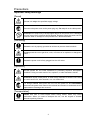


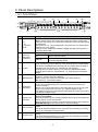


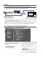
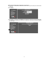
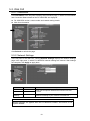
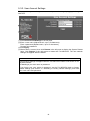
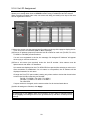

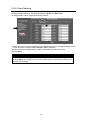
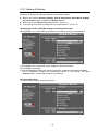

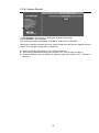

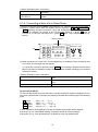
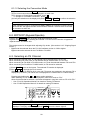

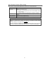
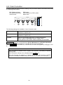
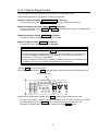
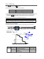
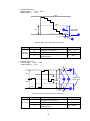
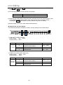


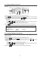
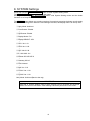
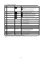
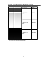
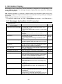
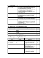
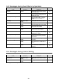


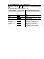
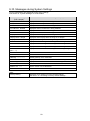

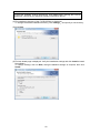
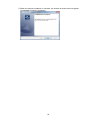

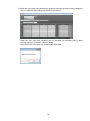
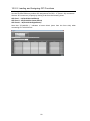
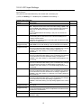
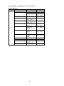
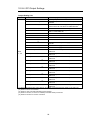


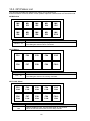
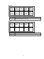

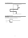
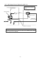
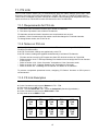

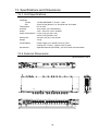

![VTW Software Operation manual[PDF:17.4MB] - FOR](http://vs1.manualzilla.com/store/data/005725901_1-df2c6d7f9199f46fcf33ffa12e63545b-150x150.png)

![FA-95RU取扱説明書[PDF:1.6MB]](http://vs1.manualzilla.com/store/data/006536810_2-6a88743f57f11a74b24ce589b01e0990-150x150.png)
![FA-AUX30 取扱説明書 [PDF:573KB]](http://vs1.manualzilla.com/store/data/006663983_2-3674fda8d18916d05af20e300767532f-150x150.png)


![UFM-30CTL Operation manual[PDF:4.1MB] - FOR](http://vs1.manualzilla.com/store/data/005676883_1-d2048345a5eb1a6d8c39e09dd604009b-150x150.png)