1
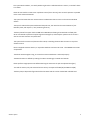
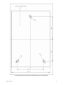
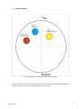
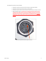
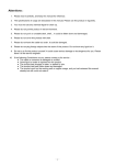
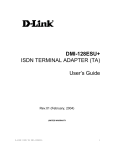
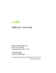
Mini-Cyclop System
Installation and user manual
Oct 1st, 2015 revision
© Alcor system
1
Table of Contents
1
System installation .................................................................................................................................................... 3
1.1
Installation ........................................................................................................................................................ 3
1.1
Cables installation ............................................................................................................................................. 6
1.1.1
Ethernet cable (#3) (if this options has been ordered)............................................................................ 10
1.1.2
Power connector and RS232 (#2)............................................................................................................ 10
1.1.1
USB connector (#3) (if this options has been ordered) ........................................................................... 11
1.1.2
Temperature sensor and humidity connector (#1) ................................................................................. 11
1.2
2
3
4
5
6
System polar alignment .................................................................................................................................. 12
Software .................................................................................................................................................................. 16
2.1
PC Minimum requirements ............................................................................................................................. 16
2.2
USB Camera driver installation software ........................................................................................................ 16
2.3
GigaBit Camera driver installation software ................................................................................................... 17
2.4
Installing the System’s control Software ........................................................................................................ 20
2.5
Installing third party camera control software ............................................................................................... 20
Using the SeeingMonitor_Cyclop software ............................................................................................................ 20
3.1
Principle of operation ..................................................................................................................................... 21
3.2
Initializing ........................................................................................................................................................ 21
3.1
Main tab .......................................................................................................................................................... 26
3.2
General Software Setup .................................................................................................................................. 26
3.3
Starting measurements ................................................................................................................................... 28
3.4
Camera control tab ......................................................................................................................................... 29
3.5
Status tab ........................................................................................................................................................ 29
3.6
The plot window ............................................................................................................................................. 30
3.7
Storage of files produced by the system......................................................................................................... 34
3.8
Seeing measurement troubleshooting section ............................................................................................... 37
3.9
TCP IP server data exchange ........................................................................................................................... 38
Front window heating control ................................................................................................................................ 39
4.1
Principle .......................................................................................................................................................... 39
4.2
Operation ........................................................................................................................................................ 39
System maintenance ............................................................................................................................................... 46
5.1
Entrance window cleaning .............................................................................................................................. 46
5.2
Inner camera desiccant replacement ............................................................................................................. 46
Product terms of use ............................................................................................................................................... 47
© Alcor system
2
1
1.1
System installation
Installation
Fig. 1 Overall system view
The system installation is simple and straightforward.
© Alcor system
3
This system works outdoor, it is totally weather-tight and is installed outside as it comes, no need of a dome
or a shelter.
Please do not install the camera near a pollution source (like a chimney). Give as much exposure as possible
to the north and avoid obstacles.
This system has heater that can remove external condensation that can occur on the entrance window
surface.
The system’s tube shall be positioned toward the polar star, this latter has the same elevation of your
latitude’s place, and requires +/- 0.2° positioning accuracy.
The base plate of this system has three M8 holes 100x160 mm allowing to be attached to a fixed pillar.
So we recommend to perform the polar alignment settings first, and clamp the system once for all into a
steel or concrete structure once performed.
This system shall not move at all, because of the wind, or building vibrations due to motors or any other
vibration source.
Use the supplied screws to attach it, or equivalent stainless steel A4 or A2 screw. Three M8x30 mm screws
are provided.
The whole camera weights 9.5 Kg, so ensure that camera attachment is achieved properly.
The North direction is defined by rotating the camera accordingly in latitude and azimuth.
Please perform image capture tests before attaching the camera to the pole as explained here (§3.1)
To install the camera, only two metric Allen hex set keys are required for M6 (#5) and M8 screw (#6).
The base plate, as depicted in figure #2 shall be horizontal and this can be checked with a bubble level.
© Alcor system
4
Fig. 2 Position of the three screws to attach the base table system to a stable structure
© Alcor system
5
1.1
Cables installation
Fig. 3 Position of the three connectors according to their function
At the backside of the tube, three waterproof connectors are present, leave enough free space at that
location to be able to install and allow the cables to run out (see fig 3).
© Alcor system
6
Fig. 4 Three cables, one is going to the temperature and humidity sensor, and other goes to inside a building.
Connectors keying and different amount of pins and gender are preventing from connection errors.
However, user must look at the number of connector pins at the end of the cable before connecting the
camera, in order to avoid forcing the pins and damage the camera connector.
Connector
see fig. 2
RED
BLUE
Cable
Number
#1
#2
YELLOW
#3
Role
Temperature sensor
Power connector and RS232 data link for weather
condition and front heating control
Camera data link
USB 2.0 link to camera or
Gigabit USB 2.0 link to camera
Gender (on
camera)
Female 5 pins
Male 4 pins
Male 6 pins or
Male 8 pins
Let the cables to go straight from the camera. If the cables shall be bent, respect a minimum curvature
radius of 100 mm. Those cable can go thought a wall, or pipes. In that case just avoid the cable to pass
underneath water despite the cable can sustain rain and snow, but not designed to be installed under water
forever.
© Alcor system
7
The waterproof connectors connect as follows:
•
•
•
•
Identify the number of connector pins of the camera, its type (male / female)
Identify the number of pins of the connector cord and match.
Identify the key pin inside the camera connector and the key at the connector cord side.
Apply a rectilinear motion. If insertion force strength persists please repeat steps for
locating the pin number and key. Excessive force applied to connector can cause the
destruction of the connector or a bad connection can damage the camera. In case of
damage due to trials to attach cable to the wrong connector kind, warranty could be
canceled.
Fig. 5 Key one of the three connectors (power connector).
© Alcor system
8
Fig. 6 Push the connector straight
Fig. 7 Then turn the connector’s collar in clockwise fashion
© Alcor system
9
1.1.1
Ethernet cable (#3) (if this options has been ordered)
Ethernet connector that goes to a PC or to a switch, both must be GigaBit compliant. If 100 Mbits
is used, the image will not go through to the PC. All chain that goes to the PC must be Gigabit
compliant (PC, Switch, routers)
1.1.2 Power connector and RS232 (#2)
This is providing power to the camera and RS232 link for weather condition and entrance window heating
control.
Fig. 8 The RS232 and power cable
The RS232 connector is a DB9 connector type female and attaches to the serial port of the PC. Usually new
PCs are not equipped with serial port, and must be equipped either:
•
•
•
© Alcor system
By a RS232 – USB converter (it can be a very moderate cost, FTDI, ATEN devices, please
avoid Prolific, there are not reliable)
By RS232 PCI card (Low cost device, not suitable for laptops)
By Serial to Ethernet (MOXA devices, very reliable and professional device
http://www.moxa.com/product/nport_device_server_1.htm ) Product type is Nport.
10
The RS232 control link is mandatory, and must be connected to your PC. This gives access to:
• Front entrance window heating control, temperature and humidity thresholds that will turn on and
off the heating control.
• setting the heat power to be applied to the front entrance window.
• reading temperature of different sensors inside and outside camera, the system has :
o one external temperature sensor
o one internal temperature sensor
o one internal humidity sensor
o one external humidity sensor
o one temperature sensor measuring the temperature of the front window
So this is a mandatory control way for the camera. Please connect the RS232 link to your PC, do not leave
it unconnected.
1.1.1 USB connector (#3) (if this options has been ordered)
This is tied up to a 6 pin connector. Please always connect the camera first and then connect to PC second,
with camera turned off. Power the camera once the USB connection is tied both sides. The cable that goes to
the PC is 20m length and is amplified.
Connect USB directly to the PC, not thru hub. The USB camera is very sensitive and does not allows USB ports
that reports issues, or been wear off by years of usage. Please be sure to have installed the latest USB
chipset software for your motherboard.
Do not put other devices on the same USB hub that requires some current.
If the camera is not recognized by the PC, try another USB port.
Despite the camera is USB 2.0, USB 3.0 PCI extra board can be used, and since they are very well powered,
most of the time, they work more nicely and more reliably than embedded motherboard USB controllers.
This is an important step, otherwise, the PC can download images for some hours, and then will not anymore
because of the USB link being not reliable.
Alcor-System has a long experience connecting USB devices using a 20m extender, and when it fails, it is
always due to PC issues, with USB chipset drivers, USB hub badly powered, USB port been jeopardized by
several Electro Static Discharge (ESD) and that had wear-out.
1.1.2 Temperature sensor and humidity connector (#1)
It is a 5-pin connector. The probe located at the end of the cord will be attached to one of the fork of the
system, and always with two set Ø4mm screws with the direction given in the next frame and horizontally.
It put upside down, this can destroy the sensor and warranty will not apply.
© Alcor system
11
Fig. 9 Up / down and horizontal temperature sensor and humidity directions for installation: never put the sensor upside down
compared to this picture
1.2
System polar alignment
The system shall aim at the polar star, so two degree of freedom can be used to do so: latitude and azimuth
axis. The system can be set roughly with a compass during the day toward the north, if magnetic local
declination angle is subtracted, then a laser during the night to allow first step alignment. In the end, fine
alignment shall be performed with the use of the software and the image from the camera.
The field of view of the system is 3.6° x 2.5°
Do not mix up the Polaris star with another star, otherwise, the star will be either too faint, will not stay for
long into the camera’s field of view and lead to false/incomplete measurements.
To align the system in azimuth direction, just rotate the base plate.
© Alcor system
12
Fig. 10 The angle depicted above has the same value of the local geographical latitude
To align it in the latitude direction, unclamp the two screws shown above with a #5 Allen wrench. One screw
is rotating and another goes over the groove.
© Alcor system
13
Fig. 11 The angle depicted above has the same value of the local geographical latitude
© Alcor system
14
Fig. 12 Sky map showing which star the system must be aimed at. This is the magnitude 2 star, Alpha Polaris from the Ursa Minor
constellation.
Never aim the system at the SUN
© Alcor system
15
2
Software
PC Minimum requirements
2.1
This system needs a PC to be connected at, to be able to work:
•
•
•
•
•
Intel I5 or better CPU Processor system.
Any system that has a CPU benchmark above index 3500, see here
https://www.cpubenchmark.net/
1024x768 display
Operating System : Windows 7, 8.1 or 10
Gigabit Ethernet interface for Gigabit camera (mandatory)
USB 2.0 port or higher for USB cameras
The system embeds a camera into the tube aiming at the polar star.
System powers up by just plugin into the main’s AC, and wait 20s to complete mini-cyclop from starting up.
USB Camera driver installation software
2.2
Connect the camera to the USB port of your PC where it needs to work with.
In the Windows device Manager form, the camera should appear with an icon tagged exclamation point on
a yellow background.
2
Fig. 13 Lists of Windows’ hardware devices
Please unzip the usbcam_driver.zip file, and run drvInstaller.exe software. The camera must be
powered and connected to proceed.
The file can be obtained from our website following this link:
http://www.alcor-system.com/common/MiniCyclop/usbcam_driver.zip
© Alcor system
16
Once installed the camera must appear as follows:
Fig. 14 USB camera properly installed and tied to the system (hardware device manager form)
After camera driver is installed, into the device manager, the yellow exclamation point will disappear and
provides the actual name of the camera. The system is ready to use.
GigaBit Camera driver installation software
2.3
Please run the gigecam_setup.exe file.
The file can be obtained from our website following this link:
http://www.alcor-system.com/common/MiniCyclop/gigecam_setup.exe
This installs a new software layer bound to the PC network adapter.
Upon installation completion, a new icon appears in the system’s tray.
© Alcor system
17
Fig. 15 The arrow show the icon of the GigECam camera IP setup panel
The camera can be connected (or can be connected during installation process), the next form shows up:
Fig. 16 This is the form that informs about the current IP camera address and allows to change it
© Alcor system
18
By default, the system is delivered with a camera that has the following persistent IP address:
192.168.1.229.
This address is suitable for networks that are like 192.168.1.x, where x ranges from 0 to 255.
For other networks, or if the address is not suitable to your network, press “Configure >>”
The camera can have his IP address set by DHCP mechanism, where the IP address is set by a router.
Fig. 17 DHCP setup
Or persistent IP address can be used according to you network. Please if you do not feel confident with
this, ask your network administrator to help you.
Fig. 18 Persistent IP setup example
If this mark appear, just do a power cycle to the system.
Fig. 19 Power cycle the system to get a valid camera icon
© Alcor system
19
2.4
Installing the System’s control Software
The software must be downloaded here:
http://www.alcor-system.com/common/MiniCyclop/setup_cyclop.exe
This is the software used to control the system click on "setup_cyclop.exe" and follow instructions
Installation is quick and trivial. Please accept all installation modules.
The software creates an icon to your desktop. We must double-click it to start the camera control software.
Fig. 20 Application’s icon in the desktop
2.5
Installing third party camera control software
IC-Capture software can be used to control the camera, but this is a basic test software, and does not have the
ability to compute any seeing figure that can SeeingMonitor_Cyclop software. Nevertheless, it can be useful to
debug camera link, or to polar align the system.
It comes along with the "setup_cyclop.exe” and is installed while this process takes place.
Warning: with IC-capture, many more setting of the camera can be accessed, SeeingMonitor_Cyclop focuses
on setting camera parameters for measuring the seeing.
Do not change the GAMMA setting of the camera with IC Capture, or if so, put it back to 100.
3
Using the SeeingMonitor_Cyclop software
This software is fairly intuitive; the documentation will focus on features that are considered difficult to use,
and about the startup procedure.
© Alcor system
20
Principle of operation
3.1
A camera embedded inside this system is aimed at the polar star from the Ursa Minoris constellation. This
star has two benefits, it is moving around a circle that has a radius of 0.75°, and is present inside the field of
view during a 24 hours rotation of the earth, meaning that no tracking is required. It is a magnitude 2 star,
and is bright enough, so that its position can be measured 50 times per seconds, using a 1/125 sec exposure
time with a green filter (550 nm).
Fig. 21 Alpha Ursae Minoris (Polaris) path that fist well inside the camera’s field of view (3.6° x 2.5°).
The star’s tip tilt motion that is measured 50 times per second, and the software computes the resulting
seeing figure at the place where the star is located, and retrieves the value of an equivalent zenith seeing.
Using the polar star is possible in geographic location from latitude 90° North down to latitude 25° North.
For other places, another star needs to be aimed at, and consecutively sidereal tracking must be enabled,
and star be changed when too far away from the zenith. In that case a DIMM system is more suitable rather
than a “Cyclop” system.
3.2
Initializing
First initialization shall take place in the night and clear skies are required, and the camera is aimed roughly
to Polaris star using azimuth and elevation freedom degrees offered by this system.
Before starting the SeeingMonitor_Cyclop software, be sure the camera is not used by another software.
© Alcor system
21
If the camera is not properly attached to the PC and or driver not installed properly, this message can pop
up, and the application will close. So please check cables, drivers and power. Try with IC-Capture.
Fig. 22 No camera is attached and detected by the software
If the link to the camera is successful, this window shows up.
The red circle and square is the position of the brightest star in the field, which should be Polaris.
The yellow large circle, shows the Polaris’ path overtime, and Polaris must be located into the “expected star
position”.
Fig. 23 The yellow cross is where the polar axis of the earth must be located in the image
The typical exposure time for Polaris is 1/125sec and camera gain must be set to the first half part of the
range.
The star must be sharp and have only several pixels of size, and must never be a big dot, or donut shape. The
system focusing is factory achieved, and user should not do it nor improve it.
© Alcor system
22
Fig. 24 Polaris to be moved toward the expected star position
Ideally, the system shall be moved very smoothly (azimuth and elevation), so that the Polaris star (red circle)
goes into the yellow circle, it does not need to be exactly centered with respect to the yellow circle, it can be
off by 20 pixels. The idea of this adjustment, is to have always the Polaris star inside the field of view of the
camera, and never stop the measurement because the star leave the field of view.
Fig. 25 Polaris located at the expected position (perfect case distance)
© Alcor system
23
Fig. 26 Polaris located at the expected position (worst case distance)
The next figure shows direction to move the system in azimuth and elevation (or latitude) to get star motion
in order to place it into the circle.
© Alcor system
24
Fig. 27 Direction for Ethernet cameras (red is the system motion)
Fig. 28 Direction for USB cameras (red is the system motion)
© Alcor system
25
3.1
Main tab
The main tab allows to change exposure time and gain of the camera. At first startup of the software,
camera exposure time and the gain are set so that the “Number of Saturated pixels:” is either 0 or 1, but
never 3 or more! Also avoid to use too short exposure time otherwise, the star is too dim and can lead to
false measurements.
Fig. 29 Polaris located at the expected position
When the software is started, the camera is set to its highest resolution (2500x1950 pixels) to be sure to
catch the Polaris star.
3.2
General Software Setup
The get it, please check the next menu
© Alcor system
26
Fig. 30
Set up your geographic place, this is important. It is meant to compute Sun set and Sun rise, and other
astronomical parameters, the seeing measurement will operate during the night, and will restart
automatically so that seeing measurement are running 24h a day, 365 days per year. The Sun’s maximum
elevation is -5° for carrying seeing measurements.
Fig. 31
© Alcor system
27
The previous screen capture sets up were the seeing measurement output plot will be uploaded to a server.
Fig. 32 TCP port for accessing last seeing measurement over a TCP client software
3.3
Starting measurements
Once the camera is polar alignment, and will be now forever, the camera can be definitely clamped, all
screws of the latitude setting tightened, the seeing measurement can take place.
The “Enable seeing measurements” can be checked and only a sub-frame of the camera where the Polaris
star sits is defined allowing readout rate of 50 images per seconds.
The “Number of measurements”, just below, indicated how much tip tilt measurements has to be carried
out before getting a valid seeing measurement. 3000 is a goof number, meaning that at 50 fps, a seeing
measurement will be computed each minute. Lower figure can be put such as low as 1000, but noise
measurement can be an issue.
Fig. 33 Enabling seeing measurements
Then measurements starts until the Sun has an elevation preventing from the measurements to occur. Also
clouds can interrupt measurements
© Alcor system
28
Fig. 34 Running seen measurements
This should run at 50 frames per second (fps), and if the computer is too busy or too slow, this might reduce
the frame rate.
3.4
Camera control tab
This tab is only visible for debugging mode of the software, so generally not visible to the end user.
3.5
Status tab
This provides the status of the system, with results of the last 3000 measurement (if set so). Also SUN
elevation is provided. Symbol “ (double quotes) stands for arcsec. Local and zenith corrected seeing are
provided.
© Alcor system
29
Fig. 35 Measurement pending (blue dot reports OK)
3.6
The plot window
The plot windows, plots results of the seeing measurement, either it will be the last 3000 tip tilt
measurement data, or seeing and star lux level for an all-night.
© Alcor system
30
Fig. 36 Zenith seeing measurement plot versus time
© Alcor system
31
Fig. 37 X and Y star motion plot (last 3000 tip tilt measurement over last 60s)
© Alcor system
32
Fig. 38 Star flux versus time (all night plot)
© Alcor system
33
Fig. 39 Star FWHM versus time (last 3000 tip tilt measurement over last 60s)
3.7
Storage of files produced by the system
The software stores all the files it produces into a directory that is specific to the user.
This directory (and subdirectories) is created automatically by the software on startup.
Fig. 40
© Alcor system
34
Under Windows 7, 8 & 10 : "C: \ Users \ [username] \ My Documents \ MiniCyclop"
• The subdirectory DATA :
This saves the measurement in different forms
Fig. 41
The Seeing_Data.txt file:
Fig. 42
This is saving for each seeing measurements (after 3000 tip tilt measurement) the computed zenith seeing,
where from left to right, the ending measurement date as UTC time, the ending measurement date as Local
time, the ending measurement date expressed in Julian days, the star flux as ADU, the zenith seeing
expressed in arcsec, and the last column is the seeing R0 fried zenith figure.
The Last_Seeing_Data.txt file:
This is the same columns as the previous file, but only the last measured is saved.
© Alcor system
35
Fig. 43
The xxxx-xx-xx-xxhxxmxxs_motion.txt file:
Where x is a digit from 0 to 9, xxxx-xx-xx-xxhxxmxxs is the date where the file has been saved.
This file is only saved if the “Save all data for seeing computation” from the setup box is checked, and
after 3000 measurements have been carried out, like set here:
Fig. 44
Fig. 45
The first column is the difference in seconds from the date when the file was created and named accordingly.
The second is the X position of the star into the detector, the third is the Y position of the date, and the last
column is the mean FWHM in X and Y direction of the star.
This can lead to large amount of data, only enable this last file if necessary.
This DATA folder can be changed if necessary, using the setup form, as follows:
© Alcor system
36
Fig. 46
• The FTP DATA folder :
This folder contains data prior to be transferred to the FTP server. This is mainly last screen copy of
plots.
• The FTP logs folder :
This folder contains FTP logs, in order to debug FTP data sending in case of failure to comply.
• The Logs folder :
This folder contains software logs, in order to debug the software, this might be requested by
ALCOR-SYSTEM to tackle bugs.
3.8
Seeing measurement troubleshooting section
This section deals with issues that prevents seeing measurement from been collected properly.
3.8.1 Pillar not been stiff enough
If the pillar is not stiff enough, the seeing measurement can be jeopardized by wind gusts. A concrete or
steal structure is recommended. When hitting the system with hands, it should not move or vibrate and be
as stiff as possible. If failing to comply with this, seeing measurement will be very noisy and correlated with
wind gusts, so pay careful attention to the structure where is attached the system. Do not leave the system
unattached to the pillar or to the structure, use bolts to attach it.
3.8.2 No data despite clear sky
© Alcor system
37
Check that the front entrance window is not covered by moisture due high relative outdoor humidity. To
overcome this, please read section 4 of this manual, the system is equipped with heater. Please connect the
camera with the RS232 link to get access to it.
3.9
TCP IP server data exchange
This is currently being developed, section will be updated as soon as possible. This allows to get the minicyclop output data from a TCP client.
© Alcor system
38
4
Front window heating control
4.1
Principle
Entrance window can be warmed up to remove condensation that can build up on its surface.
This is due to high humidity level combined with low outdoor temperature.
The system has an external temperature and humidity sensor to start or stop the heating of the front
window entrance. The temperature of this window is also monitored, so that it does not exceeded 30°C.
The control of this feature is possible by the means of a RS 232 link. This link has not tied with the camera
and uses a different channel.
Once the external temperature threshold, external humidity threshold and the power level is set, the system
has an embedded processor that takes care of the heating management of the window, even though any link
to the PC is established. This is a standalone and autonomous system.
4.2
Operation
The Serial RS232 COM port must be set to the right value (depending on your system’s settings) and click
“Connect”.
Fig. 47
If an error occur (no cable tied, or wrongly set port COM), this message will be displayed:
Fig. 48
Otherwise, the window expand and information is displayed as follows:
© Alcor system
39
Fig. 49
Top left shows outdoor temperature and humidity. Those figures will trigger the window heating. Also the
temperature of the inner part of the camera, and temperature of the front window are monitored.
A plot is showing how this figures evolves over the time. The last 2000 points are automatically saved into a
file.
© Alcor system
40
Fig. 50
When the violet curve goes up, it means that the window heating has been enabled, and stay down when
the window heating is disabled.
Fig. 51
© Alcor system
41
Fig. 52
The humidity tab, shows the outdoor relative humidity level and inner camera relative humidity.
The inner camera relative humidity shall never be above 45% otherwise, dew may form in the inner side of
the dome, and this jeopardizing measurement quality. On delivery, the camera inner humidity can be very
low, less than 5% because of desiccant presence inside the camera.
The control/setup tab allows to setup threshold temperature and humidity to allow dome heating to be
turned on or off.
© Alcor system
42
Fig. 53 Note that for Cyclop Resistance is 14 Ohms and voltage is 24V
Do not have the dome heating working all the time, during the day, for instance, this is not very useful and
advised, this can wear out the o-ring sealing quicker than expected.
The heating of the front window entrance is achieved throughout a set of resistors placed under the sphere
base. It can defog or defrost the outside side of the acrylic sphere. The inner side shall not have dew, please
refer to the inner humidity sensor figure.
The system is autonomous (works without link to PC and without user's supervision). It sets out the
conditions when temperature and humidity levels enable occurrence of water condensation.
© Alcor system
43
Fig. 54 : the violet curve rising up at 00:42:00 indicate that the front window heating is active and heating. The green curve reports
temperature of the entrance window.
As soon as the temperature is below a certain value, and moisture above another value, the heating system
is automatically activated. These levels are named temperature and humidity levels.
By default, factory set, the default threshold temperature is set to +7 ° C and humidity level to 90%. These
thresholds may be inappropriate for a given site and can be adjusted by user input.
Similarly, the heating power is set by default to 50% duty cycle, it can be changed according to site and
circumstances.
Beware, if this window is closed, getting and recording data cannot occur anymore by PC software. We
recommend that you simply hide it. Nevertheless, window’s heater activation is achieved by the camera
alone, without any link to the PC.
Finally, it is possible to transfer these plots to website for remote checking.
There is possible effects on the heating of the windows to the measurements, as shown below:
© Alcor system
44
Between 3h and 4h, the heating power was set to 50%, and has an effect on jeopardizing seen
measurements.
The next table shows the temperature increase of the window (no wind, stabilized) versus different value of
the power:
Power
50%
15%
10%
Temperature increase (Window)
+22 °C
+8°C
+6°C
So beware of the heating power, use large heating power to remove ice from the camera, in normal operation
(measurements) do not go above 10% of heating power.
© Alcor system
45
Fig. 55 Website setting for temperature and humidity plots to be uploaded
5
System maintenance
Entrance window cleaning
5.1
Entrance window cleaning must be achieved on regular basis. Consecutive rain and snow can bring dust that
is deposited on the entrance window surface; it reduces the optical transmission.
The entrance window is made of BK7 and MgF2 anti reflection coating, and it can be cleaned with water,
then with a Kleenex moistened with washer fluid dedicated for optical lens cleaning. The 8 screws can be
removed to detach the upper part from the rest of the camera, if necessary. Attention must be paid during
this phase:
•
•
•
The cable bringing power to the heaters should not be pinched during reassembly
O-rings properly positioned in their grooves with grease
8 screws must be put together and all tightened the same way.
Incorrect reassembly can cause loss of sealing, allowing water to enter and de facto warranty will no longer
apply. If you do not feel confident with dismounting the upper part, please do not do it. ALCOR SYSTEM can
offer maintenance service if required.
5.2
Inner camera desiccant replacement
To avoid any dew to form in the inner side of the entrance window, a desiccant bag made of 2A molecular
sieve is installed into the lower part of the tube that contains the camera. The inner camera relative humidity
is monitored, and should not exceed 40%. A brand new desiccant, will get relative humidity close to 5% and
can last 2 years. If replacement needs to be achieved, please contact Alcor-System ([email protected])
to know you how to proceed.
© Alcor system
46
6
Product terms of use
The use of this product is solely for monitoring the turbulence of the atmosphere, during the night for
educational or scientific purposes.
Use of this product involving people's lives is the responsibility of the user and in no way ALCOR SYSTEM will
be held liable for injuries to persons or property theft as the use of this system described in this manual.
---0O0---
© Alcor system
47