1
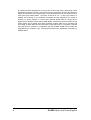
Surface Analysis and Computer Technology
Optics and Power Supplies
ErLEED
User Manual
1.2
All rights reserved. No part of this manual may be reproduced
without the prior permission of SPECS GmbH.
User manual for the ErLEED optics and power supplies.
Version 1.2 of the 04.01.2002.
SPECS order number for this manual: 78000144.
SPECS GmbH
Voltastr. 5
13355 Berlin
Germany
phone +49 30 467824-0, fax +49 30 4642083,
http://www.specs.de
[email protected]
C hapter
T
T able of contents
1.
Introduction .............................................................. 1
2.
Description of the optics ......................................... 3
2.1 General remarks ................................................................. 3
2.2 Electron gun........................................................................ 3
2.3 Grids and fluorescent screen ............................................ 4
2.4 z-retraction mechanism (optional) .................................... 4
2.5 Integrated shutter (optional) .............................................. 4
3.
Power supplies......................................................... 7
4.
Mounting of the ErLEED optics............................... 9
5.
Operation ................................................................ 10
5.1 General remarks ............................................................... 10
5.2 ErLEED 1000A................................................................... 13
5.3 ErLEED 3000D, LEED mode............................................. 14
5.4 ErLEED 3000D, RFA mode ............................................... 15
6
Maintenance ........................................................... 20
6.1 Replacement of the filament ........................................... 20
APPENDIX ....................................................................... 22
AI
2
ErLEED 1000A, Main features and
Specifications ..................................................... 23
ErLEED Optics and Power Supplies
C hapter
1
1
Introduction
Introduction
Low Energy Electron Diffraction (LEED) is one of the oldest but also one of the most
widely used methods in surface analysis. Its main application is the structure
determination of thin films and of clean and adsorbate covered crystal surfaces. In
addition, LEED is used as a standard method for the characterization of the surface
quality during the sample preparation prior to other UHV experiments. Generally, the
structural information given by a LEED pattern results from the position and the intensity
of the diffraction spots as well as from the spot profiles. In particular, the surface unit cell
of the reciprocal lattice and the corresponding real space unit cell follow from the
positions of the LEED spots. The positions of the surface atoms are obtained from the
so-called I-V curves, which means that the spot intensities are measured as a function of
the electron energy. This method allows a determination of the structure parameters of
the upper 4 or 5 layers with a precision of up to ± 0.01Å. Finally, from the spot profiles
the quality and degree of long range order at the surface can be deduced. A
measurement of the spot profile thus provides important statistical parameters of the
surface, such as average distances, defect concentrations, terrace distributions etc..
A 4-grid LEED optics can, in addition, be used as an electron energy analyzer or, more
precisely, a retarding field analyzer (RFA). This offers the possibility of recording Auger
electron spectra (AES) or energy electron loss spectra (EELS) with an energy resolution
of a few eV.
The ErLEED system has been designed at the Institute of Solid State of the University of
Erlangen-Nürnberg, Germany. It is fabricated under an exclusive license by SPECS
GmbH, Berlin, Germany.
In order to guarantee the highest possible quality and performance of each system great
importance is attached to the selection of the used materials and components as well as
to the quality of the mechanical and electronical manufacturing.
ErLEED Optics and Power Supplies
1
The optics has been designed as a reverse view or back view optics, respectively, with a
transparent fluorescent screen. That means that it is possible to observe the diffraction
pattern at the position of the LEED flange. The miniaturized electron gun obstructs only a
minor part of the LEED pattern. The optics is offered in a 2-, 3- and 4-grid version. In
addition, the mounting on a z-retraction mechanism and the integration of a shutter is
possible. As power supplies or control units, SPECS GmbH offers an analog and a
digital version (ErLEED 1000A and ErLEED 3000D, respectively). As an extension of the
LEED system the PC based video data acquisition system AIDA PC for recording and
processing of LEED data has been developed. AES data may be comfortably recorded
using the RFA-PC software in combination with the ErLEED 3000D power supply with
integrated lock-in amplifier (LIA). All mentioned products are distributed exclusively by
SPECS GmbH.
2
ErLEED Optics and Power Supplies
C hapter
2
D escription of the optics
2
Description of the optics
2.1
General remarks
The ErLEED optics is either mounted on a DN 100 CF or DN 150 CF flange. Each flange
carries the electrical feedthroughs for the operating voltages, that is a 12 pin feedthrough
DN 35CF for the electron gun and grid voltages and a HV feedthrough for the voltage
supply of the fluorescent screen. On the atmospheric side the LEED flange is equipped
with a UHV DN 100/150 CF window. Inside the vacuum the grids, the fluorescent screen,
and the electron gun are mounted on a base ring (see fig.2.1). All cables have been
fixed to the mechanical setup in a way that the view on the LEED screen is not
obstructed. For the electrical connections crimp connectors have been used which
facilitates service works. Optional there are up to two DN 16 CF UHV rotary motion
drives for a z-retraction mechanism and/or an integrated shutter.
Before the ErLEED optics is delivered it is completely checked in UHV. During those
tests the filament is carefully outgased and formed. In a seperate test report supllied with
the unit, the optimum conditions and emission currents are documented.
2.2
Electron gun
The highly compact electron gun (diameter 15 mm) consists of the cathode, the Wehnelt
cylinder, a double anode, an electrostatic single lens (elements L1,L2, L3) and the drift
tube (lens element L4 on internal ground potential) (see figure I.1) Within the standard
LEED operation the electron energy can be varied between 0 and 1000 eV. With the
ErLEED 3000D power supply energies up to 3000 eV can be set in for operation in RFA
mode. It is, however, recommended to limit the energy to about 2500 eV when the e-gun
is operated at high energies for a long period of time. The operation of the e-gun at high
energy for a long time (longer than 1 hour) leads to an increase of the pressure in the
cathode housing which results in a decrease of the cathode lifetime.
ErLEED Optics and Power Supplies
3
The construction of the e-gun ensures that no light from the cathode leaves the housing
into the direction of the LEED flange. The standard cathodes are Thoria coated Iridium
hairpin filaments and optional Lanthanum hexaboride (LaB6) filaments with specially cut
microfaces. Generally, the lifetime of the filaments depends sensitively on the pressure
-8
in the UHV chamber. For LaB6 filaments the pressure should not exceed 5 x 10 mbar.
Thoria coated Iridium filaments are less sensitive on the vacuum conditions. They may
-6
be operated at pressures in the 10 mbar range.
Important: The filament mounted in the e-gun is already outgased and formed by
SPECS GmbH before the LEED optics is delivered. Another forming of the filament at
the customer side is not necessary. The forming conditions after filament repalcement
on-side, that is current and duration of the forming procedure, are documented in the
test report included in the delivery documents of the unit.
2.3
Grids and fluorescent screen
The grids of the LEED optics are fabricated out of molybdenum. They are gold coated to
avoid potential changes as a result of work function differences. The grids and the
screen in the form of calottes with different diameters are arranged concentrically around
a common center where the sample surface has to be positioned for the diffraction and
1
spectroscopy experiments, respectively. The grid side of the screen is covered with ITO
and coated with P43 cadmium free phosphor, homogenous over the whole hemisphere.
For all electrical connections crimp connectors have been used.
2.4
z-retraction mechanism (optional)
In order to extend and withdraw the optics i.e. for evaporation processes the z-retraction
mechanism is used, which is driven by a UHV rotary motion drive (DN 16CF) on the
LEED flange. The design of the cabling and isolation enables the operation of the LEED
system in all positions and orientations. The voltages should, however, be switched off
when moving the optics.
2.5
Integrated shutter (optional)
The integrated shutter can be used to protect the optics during extensive sample
annealing, evaporation or sputtering. The voltages should be switched off when
operating the shutter. The shutter must be closed when using the z-retraction
mechanism. Restricted orientation of the LEED optics applies.
1
Indium Tin Oxide layer
4
ErLEED Optics and Power Supplies
d
Viewport
∅ 145
µ-metal shield
e-gun
165; 203 and 254
Other length on request
34
22
Rotary drive for
z-retraction
105
(optional)
HV-feedthrough
20
125
DN150CF
(8µ) flange
36°
12-way
feedthrough
85
Fig. 2.1:
151
Schematic view of the ErLEED 150 optics and the LEED flange
ErLEED Optics and Power Supplies
5
1
2
11
3
12
10
4
9
5
8
pin no.
Fig. 2.2:
6
2-grid optics
7
6
3-grid optics
1
Filament (Cathode)
2
Wehnelt
3
Filament (Cathode)
4
Anode
5
Lens Element 1
6
Lens Element 2
7
Lens Element 3
8
Lens Element 4
4-grid optics
9
-
grid 1
grid 1
10
grid 1
grid 2
grid 2
11
-
-
grid 3
12
grid 2
grid 3
grid 4
12-pin feedthrough layout on LEED flange (viewed from atmospheric side) for 2-, 3-,
and 4-grid optics.
ErLEED Optics and Power Supplies
C hapter
3
3
P o w er supp lies
Power supplies
There are two power supplies available for ErLEED 100/150 optics, ErLEED 1000A and
ErLEED 3000D for analog and digital operation, respectively.
In case of the ErLEED 1000A the high voltage modules are controlled by analog
electronic circuits. On the other hand the ErLEED 3000D power supply is driven digitally
by an integrated microcomputer. This offers a couple of interesting features concerning
the operation of the unit such as, for example, the possibility of communication with a
computer via a RS 232 interface, storing and recalling of experimental parameters, the
permanent indication of all voltages etc.. Both units can also be used in connection with
other commercial LEED optics. Please contact SPECS GmbH for further information.
With the ErLEED 1000A the primary energy of the electron is variable from 0-1000 V,
while voltages up to 3000 V can be set in spectroscopy mode with the ErLEED 3000D.
Therefore the ErLEED 3000D unit can, in addition, be used as an RFA controller for the
operation of the LEED optics as an Auger electron or electron energy loss spectrometer
(AES and EELS, respectively). Both units offer the possibility to control the electron
energy by an external analog voltage.
Within both ErLEED power supplies the true beam current is measured by a fully floating
measuring unit as potential drop across a 1 kΩ resistance between external ground and
LQWHUQDO]HUR7KHUHIRUHDFXUUHQWRI $IROORZVDYROWDJHGURSRIP9,QDGGLWLRQDOO
significant voltages are permanently displayed on digital voltmeters (DVM) in the case of
the ErLEED 1000A or on a large matrix LC display in the case of the ErLEED 3000D
power supply. The kinetic energy of the electrons corresponds to the potential difference
between the cathode and ground. The other voltages refer to the cathode potential.
The voltages at the electron lenses, at the anode, and at the Wehnelt cylinder (only for
ErLEED 3000D) vary linearly as a function of the energy with adjustable gain and offset
(see fig. 3.1). The detailed features and operation condition of the ErLEED 3000D unit is
described in detail in separate user manuals coming with the unit.
ErLEED Optics and Power Supplies
7
800
2000
Lens 2
Lens 1/3
600
voltage (V)
voltage (V)
1500
1000
offset = 100V
gain = 1.5
offset = 20V
gain = 0.5
400
200
500
0
0
0
200
400
600
800
0
1000
200
400
600
800
1000
energy (eV)
energy (eV)
1000
0
800
Wehnelt
Anode
-20
voltage (V)
voltage (V)
600
-40
offset = -7V
gain = -0.03
-60
400
offset = 350V
gain = 0.5
200
0
-80
0
200
400
600
energy (eV)
Fig. 3.1:
8
800
1000
0
200
400
600
800
energy (eV)
Voltages at lens 1/3, lens 2, Wehnelt and anode as a function of the electron
energy. A corresponding set of focusing parameters is provided in the test report
for each LEED optics. In the case of the ErLEED 1000A control unit the Wehnelt
voltage does not vary as a function of the energy.
ErLEED Optics and Power Supplies
1000
C hapter
4
4
M ounting of the E rLE E D optics
Mounting of the ErLEED optics
During transport the ErLEED optics is protected against shock and dust by a stainless
steel housing which is fixed to the LEED flange with four M8 screws. Before mounting
the optics to the UHV system a DN 100/150 CF copper gasket and the propper amount
of M8 screws or a corresponding set of thread rods, respectively, should be placed at
hand.
In the standard version the LEED flange has tapped holes. A version with bored holes is
available on request. A UHV window is already mounted and UHV leak tested. When
mounting the optics it is of great importance to work under highly clean
conditions. Each dust particle which enters the region of the grids or the screen
may lead to electric charging effects when operating the optics and may cause
severe disturbance of the LEED pattern.
After removing the four M8 screws the optics can be taken out of the stainless steel
housing. The copper gasket which is used to protect the cutting edge has to be replaced
by a new one. If the optics is kept outside the vacuum for longer time it is
recommended to cover the grids and screen in order to avoid the entering of dust
particles. The optics should, however, be mounted to the UHV chamber as soon as
possible after removal of the housing. In principle, the optic can be mounted in any
possible orientation. However, in case of an integrated shutter, a 12 o’clock mounting of
the shutter UHV rotary motion drive is highly recommended. It is not possible to mount
the ErLEED 100/150 optics bottom-up with an integrated shutter. To ensure smooth
moving be sure that the shutter is closed and the driving shaft is not engaged
when moving the mechanics.
Prior the first use the optics should be baked out. The maximum bakeout temperature is
250°C also for versions with z-retraction mechanism and/or integrated shutter.
ErLEED Optics and Power Supplies
9
C hapter
5
O peration
5
Operation
5.1
General remarks
In the following the main experimental parameters and their influence on the
performance will be summarized for the LEED mode. In the subsequent chapter the
work conditions of the optics in LEED mode will be explained separately for ErLEED
1
1000A and for ErLEED 3000D units . Finally, the operation and optimisation of the
ErLEED system in the RFA mode will be described in chapter 5.4.
Influence of the gun elements
The Wehnelt cylinder acts as an electrostatic aperture between the cathode and the
anode. It is on the same or on a negative potential with respect to the cathode and
regulates the penetration of the anode potential into the direction of the cathode. An
increase of the Wehnelt voltage leads to a narrowing of the electron beam. By that
means the sharpness of the diffraction spots can be improved. However, if the voltage is
increased above a certain value the spot intensities decrease and become completely
suppressed, finally. The optimum Wehnelt voltage slightly depends on the energy. This
was taken into consideration in the concept of the ErLEED 3000D control unit where the
Wehnelt voltage varies linearly as a function of the energy with adjustable gain and
offset.
The anode is always on a positive potential with respect to the cathode. It accelerates
the electrons emitted by the filament into the direction of the lens elements. The
optimum anode voltage is energy dependent, too. Therefore the ErLEED control units
provide an adjustable gain and offset of the anode voltage in order to obtain a good
focus over a broad energy range.
1
The ErLEED 3000D unit can be operated using front-panel input exlusively. Via the RS232 interface and RFA-PC
software the unit can also be fully controlled by using a computer. Both possibilities are described in detail in two
separate user manuals, ErLEED 3000D and ErLEED RFA-PC, respectively.
10
ErLEED Optics and Power Supplies
The lens elements 1, 2 and 3 constitute an electrostatic single lens which is essentially
responsible for the shaping of the electron beam. In the diffraction experiments the
electron source or, more precisely, the cross-over point in front of the cathode is focused
on the fluorescent screen where the sample acts as a mirror plane. On the contrary the
source is focused on the sample in the spectroscopy setup. The lens elements 1 and 3
(labelled lens 1/3) are on the same potential while the potential of lens 2 is independent
of lens 1/3. In order to obtain a sharp focus over a broad range of energies the lens
voltages have to vary as a function of the energy. Therefore the energy-voltage
characteristics are fitted by a linear curve with gain and offset.
While the quality of the focus at low energies is mainly determined by the offset, the
adjustment of the gain becomes important at higher energies (>300 eV). In addition,
there is a strong interdependence of the voltages at lens 1/3 and lens 2. The general
focusing procedure is to optimise all offset voltages of the e-gun elements at low
energies (<50eV) and then switching to high energies (>300eV) to adjust the
corresponding voltage gains leaving the offsets unchanged. By repeating these steps
several times a broad range focus is obtained iteratively.
Alternative focus conditions
Due to the large number of adjustable voltages (Wehnelt, anode, lens 1/3, and lens 2)
there exists more than one optimum combination of the values. Which one is chosen,
finally, depends on the respective experimental requirements. It might, for example, be
necessary to have a good focus over a broad energy range, the sharpest possible or the
most intense spots etc.. The values stated in the ErLEED test report constitute a
compromise between a broad range focus (between about 50 and 500 eV) and a
homogeneous beam profile in this energy range. In special cases there exists the
necessity of a higher beam current or narrower spots in a smaller range of energies. The
standard parameter setup may serve as a good starting point to find a setting which is
more appropriate for the given experimental conditions.
Filament
The optimum filament current is a compromise between the largest possible emission
(which varies nearly exponentially as a function of the temperature of the filament), a
sharp focus, and the smallest possible heating of the cathode environment. Such a
heating results in an increase of the pressure around the cathode which leads to
sputtering of the active cathode surface and thus to a shortened lifetime of the cathode.
Due to a temporary deterioration of the vacuum conditions in the UHV chamber (e.g.
after bakeout, gas deposition etc.) a decrease of the emission current is possible. In this
case the filament can be reactivated by applying the cathode forming current for some
minutes. The appropriate forming current is stated in the test report. After the
reactivating procedure the current has to be reset to its normal value to avoid a
premature ageing of the filament.
ErLEED Optics and Power Supplies
11
Beam current measurement
The beam current corresponds to the part of the electrons emitted by the filament which
pass all apertures and lens elements and, finally, leave the electron gun. It depends
therefore on the emission current as well as on the energy and the focus voltages.
Having left the electron gun the electrons hit the sample and flow back to the control unit
across common ground. This current causes a voltage drop across a 1kΩ resistance,
i.e. 1 A causes a 1mV voltage drop, which can be measured at the IO monitor socket at
the rear of the control unit.
Fluorescent screen
In order to make the electrons visible on the fluorescent screeen it is necessary to apply
a positive high voltage between 5 and 7 kV to the screen. In the case of the ErLEED
3000D control unit the difference between the cathode and the screen potential is kept
constant, i.e. the screen voltage decreases with increasing electron energy with the
amplification becoming independent of the electron energy.
Suppressor
Secondary electrons and electrons which are inelastically reflected by the sample (with
energy losses of some 10 eV) can be kept away from the fluorescent screen by applying
a negative voltage to the suppressor grids (grid 1 for the 2-grid optics, grid 2 for the 3grid optics, grid 2 and 3 for the 4-grid optics). This results in a reduction of the
background on the LEED screen as only elastically reflected electrons and electrons with
small energy losses contribute to the diffraction pattern. The suppressor voltage varies
linearly as a function of the energy with zero offset.
At very small suppressor voltages (narrow energy window) a weak defocusing of the
diffraction beams is observed. This is due to a slightly inhomogenous potential
distribution in the vicinity of the grids and deviations from an absolutely radial symmetric
propagation of the electrons.
Sample position
In order to generate a diffraction diagram on the LEED screen a well prepared single
crystal surface has to be placed in the center of the grids and screen. If the sample
position is not correct the diffraction pattern is distorted. In particular, the unit cell
appears slightly “blown up” if the sample is too close to the optics while it looks “deflated“
if the sample distance is too large. In addition, the underground in the diffraction pattern
is inhomogeneous when the suppressor voltage is varied in the region of small voltages.
Furthermore a broadening of the diffraction spots and a shift of the spot positions is
observed. The position and the intensity of the diffraction spots depend sensitively on
the energy. The sharpness of the spots is on one hand dependent on the voltages at the
lens elements, the Wehnelt cylinder and at the anode. On the other hand it is a function
of the quality of the sample surface, i.e. of the cleanliness of the surface and the degree
of the long range order.
12
ErLEED Optics and Power Supplies
5.2
ErLEED 1000A1
The ErLEED optics should only be operated at a base pressure in the UHV chamber
-8
lower than 5 x 10 mbar if a LaB6 filament is used. For Thoria coated Iridium filaments
-6
the pressure should be in the 10 mbar range.
• Before switching on: Check the line voltage (red commutator at the rear of the
2
unit).
• Connect the mains plug
• Check if the screen voltage is set to "OFF".
• Connect the SHV cable to the High Voltage output at the rear of the unit and to the
HV feedthrough for the screen voltage at the LEED flange of the optics.
• Connect the multipin cable to the rear of the unit and to the 12-pin feedthrough at
the LEED flange.
• Check if the potentiometer for the adjustment of the filament current is set to "OFF".
• Switch on power
The digital meters on the front of the unit display the actual currents and voltages.
• Set the voltages at the electron gun (Wehnelt, anode, lens 1/3, lens 2) to the values
in the test report using the corresponding potentiometers for gain and offset.
The respective offset voltages are determined by extrapolation of the voltages in the
test report to E=0eV. The offset is adjusted with the electron energy set to zero. In a
second step the gain of the electron gun voltages is adjusted by setting the energy to
100eV or 300eV, respectively, and adjusting the voltages to the corresponding values
given in the test report.
• Set the suppressor voltage to maximum in order to maximize the energy window for
the transmission of the electrons.
• Set the screen voltage to 6 kV.
• Set the energy to about 100 eV.
• Switch on the filament heating current and set the current slowly (within about 30
sec) to the value which is given in the test report.
3
In any case, avoid overheating of the filament. Keep in mind, that the emission
(anode current) increases exponential with the filament current increasing
linear.
The anode current should increase within a few seconds. It decreases significantly
when the Wehnelt voltage is increased.
• Adjust and optimize sample position.
1
Please refer to Appendix AI for a more detailed description of the ErlEED 1000A unit.
Redudant since 2001: units are now supplied with wide range power supplies for a direct 110V or 220V connection.
3
Safety button since 2002: Push to operate.
2
ErLEED Optics and Power Supplies
13
5.3
ErLEED 3000D, LEED mode
As far as the LEED mode is concerned the ErLEED power supplies are more or less
identical in their functionality. Nevertheless they differ from each other significantly by
their control possibilities. As mentioned earlier the ErLEED 3000D unit can be controlled
1
by either front-panel input in a quasi-analog manner or with the RFA-PC software. The
mode of operation is indicated on the front display and can be selected in the System
Menu or within the RFA-PC software. The LEED mode operation in this chapter is
described with using the front-panel input (Please refer to ErLEED 3000D user manual).
The spectroscopy mode in chapter 5.4 is explained by using the RFA-PC software
(Please refer to ErLEED RFA-PC user manual).
The ErLEED optics should only be operated at a base pressure in the UHV chamber
-8
lower than 5 x 10 mbar if an LaB6 filament is used. For Thoria coated Iridium filaments
-6
the pressure should be in the 10 mbar range.
• Before switching on: Check the line voltage (red commutator at the rear of the
2
unit).
• Connect the mains plug.
• Connect the SHV cable to the screen voltage output at the rear panel of the unit
and to the HV feedthrough for the screen voltage at the LEED flange of the optics.
• Connect the multipin cable to the grids/e-gun voltage output of the power supply
and to the 12-pin feedthrough at the LEED flange.
• Check if the SENSE input of the power supply is short-circuited either by a BNC
end connector or by an external device (for example the trip output of a BayardAlpert ionization gauge).
• Switch on power. An acoustical signal is heard; a self-test and the calibration of the
unit is performed during about 10 sec.
• Set the voltages at the electron gun (Wehnelt, anode, lens 1/3, lens 2) to the values
in the test report using the corresponding potentiometers for gain and offset. Refer
to chapter 7 of the ErLEED 3000D user manual for a description of the operation of
the control devices of the power supply.
The respective offset voltages are determined by extrapolation of the voltages in the
test report to E=0eV. The offset is adjusted with the electron energy set to zero. In a
second step the gain of the electron gun voltages is adjusted by setting the energy to
100eV or 300eV, respectively, and adjusting the voltages with gain control to the
corresponding values given in the test report.
• Select the mode of the primary energy control of the power supply (internal,
external, remote, RS232, see chapter 7 of the ErLEED 3000D user manual). Set
the energy to 100 eV.
• Set the suppressor voltage to maximum in order to maximize the energy window for
the transmission of the electrons.
• Switch on the screen high voltage and set it to 6 kV.
1
2
I.e. the energy and all volatges can be controlled with a knob on the front-panel of the unit.
Redudant since 2001: units are now supplied with wide range power supplies for a direct 110V or 220V connection.
14
ErLEED Optics and Power Supplies
Although the ErLEED 3000D power supply provides a maximum screen voltage of 10
kV it is sufficient in most cases to work at lower voltages. Instead a maximum value of
7 kV is recommended. For safety reasons the screen voltage and the filament heating
are immediately switched off by the control unit if a spark-over is generated when
working at extreme voltages.
• Switch on the filament and set the filament current to the working value given in the
test report. The anode current should increase within a few seconds.
In any case, avoid overheating of the filament. Keep in mind, that the emission
(anode current) increases exponential while the filament current is increased
linearly.
The filament current is set to zero when the filament voltage is switched off. The value
of the heating voltage is, however, stored. In the case of a change of the mode of
operation or of switching on/off the control unit the filament heating voltage is
automatically set to zero.
• Adjust and optimize sample position.
Once a suitable set of focus parameters is found we recommend to store it using the
internal memory of the ErLEED 3000D power supply. The storing and recalling of
parameter settings is explained in chapter 7.10 of the ErLEED 3000D user manual.
5.4
ErLEED 3000D, RFA mode
In the RFA mode the ErLEED 3000D power supply provides all necessary voltages to
operate a LEED optics as a retarding field analyser (RFA) for electron energy loss
spectroscopy (EELS) or Auger electron spectroscopy (AES) with a maximum adjustable
primary electron energy of 3 keV. For data recording an integrated Lock-In amplifier and
RFA-PC software is used. The software is described in a separate ErLEED RFA-PC
user manual. All references in this chapter are based thereon although operation is
possible with front-panel input as well. An external Lock-In amplifier can be used optional
with a diffrent version of RFA-PC.
In order to obtain an energy resolution which is sufficient for spectroscopy experiments a
highly homogenous retarding field is required. Therefore a 4-grid LEED optics is
necessary for this kind of experiments.
The ErLEED optics should only be operated at a base pressure in the UHV chamber
-8
lower than 5 x 10 mbar if an LaB6 filament is used. For Thoria coated Iridium filaments
-6
the pressure should be in the 10 mbar range.
ErLEED Optics and Power Supplies
15
∞
The signal at the fluorescent screen is
∫ N ( E )dE where N(E) is the energy
eU ( Supp )
distribution of the electrons emitted from the sample and USupp the suppressor voltage at
grids 2 and 3 of the optics. The energy distribution N(E) itself and its first derivation N’(E)
are obtained using Lock-In technique. For that purpose the cutoff voltage at the
suppressor grids, is modulated with a fixed frequency ω. The corresponding intensity
variation on the fluorescent screen serving as the electron detector is read out by a
Lock-In amplifier (LIA). Then the energy distribution N(E) is obtained from the oscillation
amplitude of the 1ω Fourier component of the signal. The amplitude of the 2ω
component is giving the first derivation N’(E) which corresponds to the standard
representation of the spectra of Auger electrons excited by an electron beam. In
comparison to the differentiated spectra the undifferentiated spectra N(E) have the
disadvantage that small peaks are often hidden by the strong background of secondary
electrons.
The oscillator circuit providing the modulation voltage in the ErLEED 3000D power
supply works at a preset, quartz-stabilized frequency of 1050 Hz (“1f“ mode activated) or
2100 Hz (“2f“ mode activated), respectively. The maximum peak-to-peak amplitude is
12 V. The oscillator signal is monitored at the "f_OUT" output on the rear of the control
unit. The reference frequency at the "f_REF" output is always twice the frequency of the
oscillator in the “1f“ mode.
For standard operation the oscillator and the LIA are set to the “1f“ mode each and the
voltage at the "f_REF" output is us as the reference signal for the lock-in detection. The
output signal of the LIA is then the first derivative of the energy distribution, i.e. N'(E).
When the "2f" mode of the oscillator is set the modulation frequency is identical to the
reference frequency. In this case the energy distribution N(E) is obtained at the output of
the LIA.
The frequency of the oscillator can be varied in discrete steps between 750 and 1250Hz
(please refer to chapter 7.5.7 of ErLEED RFA-PC user manual). It should, however, only
be varied in special cases as such a variation makes a recalibration of the frequency
filter in the matching unit necessary.
An electric charging of the screen is avoided by applying a positive voltage of about
500 V to it. In order to separate this voltage from the measuring signal a matching unit
has to be placed between the output of the screen and the input of the LIA. In the
matching unit used in connection with the ErLEED 3000D control unit an active
frequency filter and a low noise signal preamplifier are integrated, additionally.
When "OUTPUT 1" is activated, the voltage at the suppressor grids 2 and 3 is
modulated. If "OUTPUT 2" is active, the modulation is applied to the cathode potential.
As the energy of Auger electrons is independent of the excitation energy they can only
be detected by a modulation of the suppressor voltage. If instead the primary energy
(cathode potential) is modulated only those electrons with an energy depending on the
primary energy will contribute to the signal at the output of the LIA. An example for the
second case are the elastically reflected primary electrons with an energy loss of 0 eV.
Switching from OUTPUT 1 to OUTPUT 2 therefore allows to distinguish between energy
loss electrons and Auger electrons in the spectra.
16
ErLEED Optics and Power Supplies
Concerning the setting of the LIA and the ErLEED 3000D control unit it is recommended
to optimize the parameter adjustment using the strong primary peak of the elastically
reflected electrons. In a second step the spectrum of the much weaker Auger transitions
can be recorded. The procedure of the recording of the primary peak and the Auger
spectra, respectively, will be described in the following.
Detection of the primary peak
• Before switching on the power supply the matching unit has to be connected to the
HV-feedthrough on the LEED flange. In addition to the signal matching circuit the
matching unit contains a frequency filter and a preamplifier. In order to provide the
necessary supply voltage of ± 12 V the DIN cable coming from the matching unit
has to be plugged into the socket labeled “supply” on the rear of the ErLEED 3000D
unit.
• The signal output corresponding to the low voltage BNC socket on the matching
unit has to be connected to the input of a Lock-in amplifier (LIA).
• The medium voltage BNC socket on the matching unit has to be connected to the
collector voltage output at the rear of the power supply.
• The BNC socket labeled "REF" on the rear of the control unit provides the
reference signal (which corresponds to 1f or 2f of the oscillation frequency applied
to the suppressor grids, respectively) for the Lock-In detection. It has to be
connected to the reference input of the LIA which has to be set to 1f reference
mode.
• In case of an integrated LIA data are recorded and displayed by RFA-PC software.
In order to record a spectrum manually the output of the LIA has to be connected to
the Y-input of a XY-recorder or to a computer, respectively. The energy axis
corresponding to the X-axis is driven by the U_Mon output on the rear of the
ErLEED 3000D.
• Switch on the power supply.
• Set the primary beam energy to 1000eV
• Adjust the focus parameters according to the values given in the attached test
report.
In the RFA mode of the power supply the voltages at lens 1/3 are set equal to the
anode potential. For focusing of the gun only the offset voltages are used as the
primary energy of the electrons is, generally, kept constant during the experiments so
that no broad range focusing is needed. The screen high voltage is not active in the
RFA mode. Instead a collector voltage of up to 500V is applied to the screen in order
to avoid electrical charging.
• Switch on the filament.
• Set the filament current to the working value given in the test report.
• Adjust the sample position.
In order to obtain the highest possible energy resolution the sample has to be
positioned in the centre of the screen. The tolerance is only a few millimeters. In
addition the sample surface normal should be parallel to the optical axis of the LEED
optics.
ErLEED Optics and Power Supplies
17
• Set the collector voltage to 500V .
• Activate the ramp generator and set the start and final energy of the scan to 950 eV
and 1050 eV, respectively.
• Set the scan time to 100 sec.
• Set the modulation amplitude to about 4 V peak-to-peak depending on the height of
the signal.
• Select OUTPUT 1 of the oscillator to modulate the voltage at the suppressor grids.
Setting of the Lock-In amplifier
• Set the input frequency filter (Bandpass, Low or Highpass, respectively) to f = 2100
Hz.
• Set the input sensitivity to about 1 meV depending on the height of the signal.
• Set the "1f" reference frequency mode.
• Set the time constant to TC = 0.3 sec or TC = 1 sec.
In order to maximize the output signal of the LIA the phase shift between the
measuring signal and the reference signal has to be adjusted. In addition, the deviation
N’(E) of the primary peak has to show a maximum on the low energy side and a
minimum on the low energy side with the maximum and the minimum having approximately the same amplitude.
In the case of a strongly asymmetric primary peak the position of the sample should be
checked.
Hint: The fastest method to optimize the phase matching of the LIA is to select the
manual mode of operation and to maximize the amplitude of the primary peak in the
differential spectrum with the energy set to the value corresponding to the peak
maximum or minimum, respectively.
• Finally, having optimized the phase of the LIA and the sample position the signal
may, eventually, be further increased by a fineadjustment of the focus voltages
(please refer to chapter 7.5.4 of the ErLEED RFA-PC user manual). This further
increase can be due to an increase of the beam current as well as to a sharper
focus of the electron beam on the sample surface.
Detection of Auger electrons
Once the optimisation of the signal for the primary peak is finished neither the sample
position nor the settings of the phase and of the electron gun voltages should be
changed afterwards. However, in order to record an AES spectrum in the N’(E) mode a
few parameters have to be readjusted.
• The start and the final value of the energy scan have to be set.
• The scan time has to be increased by a factor of 5 to 10, approximately.
• The input sensitivity of the LIA has to be increased by a factor of 100 to 1000.
18
ErLEED Optics and Power Supplies
• The time constant has to be increased by a factor of about 5 to 10.
Hint: In general, the noise level in the resulting Auger spectra is more significant than
in the spectrum of the primary peak. It could, in principle, be reduced by choosing a
higher time constant of the LIA. In order to keep the energy resolution constant an
increase of the time constant has, however, to be compensated for by a decrease of
the scan velocity. Finally, a smoothing of the spectra by means of a computer will only
in certain cases improve the quality of the measurement since important information is
lost as a consequence of the smoothing procedure.
ErLEED Optics and Power Supplies
19
C hapter
6
M aintenance
6
Maintenance
6.1
Replacement of the filament
The lifetime of the filaments used in the ErLEED optics depends crucially on the working
conditions. It is therefore recommended to carefully outgas the filaments after bakeout
-8
and to avoid working at base pressures above 5 x 10 mbar. In particular, LaB6 cathodes
react rather sensitively to any kind of contamination of their surface. It might therefore be
necessary to carefully reactivate the filament from time to time to reestablish stable
emission characteristics, e.g. after bakeout of the chamber or after exposure to surface
contaminants like CO, CmHn, etc.. The filament of the ErLEED electron gun needs to be
replaced when it is fused or when the emission characteristics deteriorate significantly
due to excessive contamination of the cathode surface that cannot be removed by
reactivation.
Spare filaments are usually available from stock at SPECS GmbH.
In the following the working steps required for the replacement of the filament will be
explained in detail.
Important: Choose a clean and dust free place in or outside of your laboratory for the
exchange of the filament. In addition, we recommend to wear gloves when working on
the optics.
• Remove the optics carefully from the UHV chamber. Put a clean cover on top of the
µ-metal or stainless steel shield to prevent the grids from being contaminated by
dust particles.
• Loosen the three M2 screws around the (magnetic) shielding and carefully remove
the shielding from the optics.
• Disconnect the connectors from the contact pins spot welded to the grids and
screen, respectively. Note the number of the grid each cable is assigned to.
20
ErLEED Optics and Power Supplies
• Loosen the 3 M4 nuts on the upper mounting ring carrying the assembly of grids
and screen. Take off the mounting ring and put the whole assembly under a clean,
dust free cover.
• Carefully remove the end cap from the Wehnelt cylinder. If the end cap does not
come off easily be careful not to damage the ceramic holder when exerting
increased force on the electron gun. In addition, pay attention to the glass fiber
isolation of the two cables for the cathode current supply. Note the position and the
way the cables are laid.
• Remove the cables from the filament contact pins.
• Pull the fixing cylinder out of the electron gun. Note the position of the lateral groove
in the cylinder with respect to the Wehnelt cylinder.
• The old filament can now be taken out of the electron gun by pulling equally on both
contact pins. Note the position and orientation, respectively, of the contact pins of
the filament with respect to the Wehnelt cylinder. The ceramic base plate of the
filament breaks easily if unequal force is exerted on the pins. If this happens make
sure that no fragments of the ceramics remain in the electron gun before mounting
the new filament.
• The filament base plate sits on a distance holder inside the Wehnelt cylinder
ensuring the correct position of the filament tip with respect to the Wehnelt
aperture. The distance holder has four venting bores in its side. These have to be
orientated at 45° with respect to the corresponding bores in the surrounding
Wehnelt cylinder such that during operation of the filament no light can leave the
electron gun into the direction of the LEED flange.
• Carefully introduce the new filament into the Wehnelt cylinder maintaining the
position and orientation of the contact pins of the old filament. Make sure that the
base plate sits evenly on the distance holder.
• Remount the fixing cylinder maintaining the previous orientation of the groove.
• Carefully connect the cables to the contact pins of the filament and lay the cables
respecting the previous way of laying.
• Put the end cap onto the Wehnelt cylinder. Pay attention to the isolation of the
cables.
• Remount the grids/ screen assembly and reconnect the cables.
• Remount the µ-metal or stainless steel cylinder. Make sure not to damage the
isolation of the cables when the cylinder is slided over the mounting ring.
When the new filament is set to operation for the first time it is necessary to carefully
outgas the electron gun. Make sure that the pressure rise in your UHV chamber due to
the heating of the filament does not exceed the range of 10-8 mbar. In addition, the
filament needs to be activated (or formed) in order to obtain stable emission
characteristics. This applies particularly to LaB6 filaments which usually require several
hours of operation at elevated currents (appr. 2.0 Amps) for activation.
If you have any further questions or in the case of doubt, please, do not hesitate to
contact Specs for further instructions.
ErLEED Optics and Power Supplies
21
C hapter
A
22
A ppe ndix
ErLEED Optics and Power Supplies
C hapter
AI
AI
E rLE E D 1000A , M ain features
ErLEED 1000A, Main features and Specifications
In the following the main features of the ErLEED 1000A control unit will be summarized.
• Size: 19“ rack, height 182 mm, weight 10 kg.
• Fully floating unit measures true beam current.
• Electron energy variable between 0-1000eV.
• 5 high stability HV modules for independent supply and control of all voltages.
• The lens voltages (L1/3 and L2) and the anode voltage vary linearly as a function of
the electron energy with individually adjustable gain and offset. The suppressor
voltage varies linearly without offset.
• The filament current, the electron energy, the Wehnelt, the suppressor, and the
fluorescent screen voltage as well as the offset and gain of the lens and anode
voltages are set by potentiometers on the front of the unit.
• 3 digital meters for current and voltage display. The cathode potential
corresponding to the electron energy is measured in reference to the internal
ground. The Wehnelt, anode, suppressor, and lens voltages are measured and
displayed relative to the cathode potential.
• Monitoring outputs for beam current (10) and electron energy.
• 0-10V voltage input for the external (remote) control of the electron energy.
• Currents and voltages supplied by the HV modules:
cathode:
0-1000 V, 2 mA
lens 1/3:
0-2000 V, 1 mA
lens 2:
0-1000 V, 1 mA
anode:
0-1000 V, 2 mA
fluorescent screen:
0-7.5 kV, 0.75 mA
Wehnelt:
0-150 V
ErLEED Optics and Power Supplies
23
Controlling devices, front panel
1.
Digital voltmeter 1 (DVM 1) for the display of the energy in eV and the Wehnelt,
anode, lens and suppressor voltages in V.
2.
DVM2 for the display of the filament current in A
3.
DVM3 for the display of the anode current in mA
4.
Selector switch for DVM 1
5.
Adjustment of the energy (cathode potential)
6.
Adjustment of the filament heating voltage with ON/OFF switch
7.
Adjustment of the Wehnelt voltage
8.
Adjustment of the gain of the anode voltage
9.
Adjustment of the offset of the anode voltage
1
10. Adjustment of the gain of the suppressor voltage
11. Adjustment of the voltage at L1/3, gain
12. Adjustment of the voltage at L1/3, offset
13. Adjustment of the screen voltage
14. Adjustment of the voltage at L2, gain
15. Adjustment of the voltage at L2, offset
16. Control LED for filament current
17. Control LED for screen voltage
18. Power switch
Controlling devices, rear panel
1)
Socket for mains plug
2)
Commutator 110V/220V line voltage
3)
Ventilator
4)
Multipin socket for the connection of the 12-pin cable leading to the LEED optics
2
(electron gun and grids)
1
2
5)
SHV-BNC socket for the fluorescent screen high voltage
6)
BNC socket of I0 monitoring output
7)
0-10V voltage input for external control of electron energy
8)
Selector switch for internal / external control of electron energy
Safety button since 2002: Push to operate.
Redudant since 2001: units are now supplied with wide range power supplies for a direct 110V or 220V connection.
24
ErLEED Optics and Power Supplies
C
W
A
L1
L2
L3
L4
S
G1...4
Filament
Umax = 5V
Imax = 3A
Wehnelt
Umax = 150V
Anode
Umax = 1000V
Imax = 2mA
L1/3
Umax = 2000V
Imax = 1mA
Suppressor
Umax = 350V
L2
Screen
Umax =1000V
Imax = 1mA
Umax = 7.5kV
Imax = 0.75 mA
Energy
Umax = 1000V
Imax = 2mA
Fig. I.1:
Block diagram of the ErLEED 1000A control unit showing the voltages applied to
the electron gun, the fluorescent screen and the grids of the LEED optics. A 4 grid
optics is used as an example.
ErLEED Optics and Power Supplies
25
2kV
1
2
3
Suppressor
Voltage
Cathode Current
10
6kV
Off
Screen
17
13
Anode Current
ErLEED 1000-A
Energy
Wehnelt
16
Anode
L1/3
4
L2
Suppressor
6
Off
8
Cathode
5
1 2
Fig: I.3:
11
L1/3 Gain
9
Wehnelt
Fig. I.2:
5
Anode Gain
7
Energy
26
4kV
OkV
Anode Offset
14
L2 Gain
12
L1/3 Offset
POWER
15
L2 Offset
Front panel of the ErLEED 1000A control unit. The function of the devices is
described in the text.
6
7
8
3
4
Schematic view of the back panel of the ErLEED 1000A control unit. The function
of the devices is described in the text.
ErLEED Optics and Power Supplies
18