1
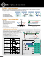
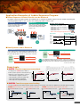
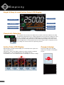
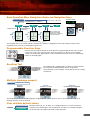
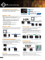
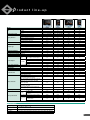
Full Control at Your Finger Tips
Digital Indicating Controllers
UT55A / UT52A / UT35A / UT32A
Bulletin 05P01A01-01EN
www.utadvanced.com
INTRODUCING THE
Balancing Simplicity and Power
The UTAdvanced was designed as a result of
knowledge obtained in Yokogawa’s fifty plus years
of experience in the control market. Significant
changes in the market are setting the tone for the
future and Yokogawa will be leading the way meeting
the challenging needs of the control segment.
Balancing an easy to use controller with the power
to handle your most challenging applications, that’s
the UTAdvanced.
2
features
Advanced Control
PID Control — 8 built-in Control Functions
— 8 built-in Control Algorithms
Ladder Sequence Control
Fuzzy Logic Control
Simplicity
Bright & Easy to read Active Color LCD Display
Scrolling Text
Navigation Guide & Navigation Keys
Programmable function keys
User settable default values
Multiple language support
Compact design
Networking
CSA C22.2 61010-1
172608
UL61010-1
Ethernet (Modbus / TCP)
RS485 (Modbus / RTU, Peer to Peer, Coordinated Operation, PC-Link)
PROFIBUS-DP
Reliability
3 year warranty *Note 1
RoHS / WEEE
NEMA4*Note 2 / IP56 front panel
Note 1 : The 3 year warranty extends 36 months after shipment from our factory.
Note 2 : Hose down test only.
3
advanced
Control
8 built-in Control Functions
Eight of the most commonly used control functions are built in to the UT52A and UT55A. A simple configuration change within
the UTAdvanced allows any one of the eight preset control schemes to be used.
• Single-loop control*
PV auto-selector
PV switching
Cascade control
Loop control for backup
• Cascade primary-loop control
• Cascade secondary-loop control
• Cascade control
SELECT
PID
PID
• Loop control for backup
• Loop control with PV switching
PID
PID
PID
• Loop control with PV auto-selector
• Control with PV-hold function
(The UT35A/UT32A support control marked with an asterisk (*) only)
8 built-in Control Algorithms
• PID control*
• ON / OFF control (1 point of hysteresis)*
• ON / OFF control (2 points of hysteresis)*
• Two-position, two-level control*
• Heating / cooling control*
• Sample PI control
• Batch PID control
• Feedforward control
Output(%)
100
Cooling-side
output
SP
PV
Heating-side
output
Integral action
P+I
OUT
0
Output held
Output held
Time
Control start point
Dead band
Heating / cooling control
Sample PI control
(The UT35A/UT32A support control marked with an asterisk (*) only)
Ladder sequence Control
Ladder sequence Control
With built in ladder sequence control, the range of applications
covered by single loop control are dramatically increased.
This feature is standard in all the UT52A/UT55A controllers. The
ladder sequence control function can replace a small PLC required
by the application. Integrated sequence and PID control.
• Monitoring and control of external machinery
Eg. Lamps, switches, timers
• Solve digital input / output logic functionality easily.
Number of basic command types : 13
Number of application command types : 71
Name
Symbol
PV>SP
Timer start
DI2 OFF: Control stop
Timer time out
Control stop
SP
Hardening time
PV
PV in control stop
Time
DI2 ON: Control start
Load
PV in time out
X_DI2
Set
SET
Timer
TIM
Counter
Temperature
SET
RST
CNT
PV
SP
Control start flag
TIM
Logic
&
X_DI2
=
SET
M02
PV>SP flag
M02
>
RS_L1
Control run mode
M01
Compare
M01
Control start flag
Control start relay
CLK1
TIM1
K1
RST
M01
Hardening timer
Control stop relay
Control start flag
TIM1
Data transfer
High selector
RST
MOV
Quenching timer
HSL
TIM1
Hardening timer
RST
M02
PV>SP flag
Temperature correction
TCMP1
* LL50A Parameter Setting Software (sold separately) is required to build
functions.
4
X_DI2: DI2
M01 to M02: Internal relay
K1: 3600
SET
RS_L1
Control stop mode
Application Examples of Ladder Sequence Program
n Alarm Sequence Control Circuits can be Reduced
The ladder sequence program is built in the UTAdvanced as standard. The ladder sequence function enables monitoring and
controlling peripheral devices such as relays, thus making it possible to reduce costs.
Conventional
UTAdvanced
Alarm action was built by a sequence
control circuit (relay, timer, etc.)
outside of the controller.
Example: Alarm annunciator
Action explanation
• Lamp blinks when alarm occurs
• Lamp turns on by acknowledgment
when alarm is on
• Lamp turns off by acknowledgment
when alarm is off
Alarm acknowledgment by function key
Alarm action is built by the ladder
sequence program inside the UTAdvanced, thus making it possible to
reduce costs.
Alarm
sequence
control
circuit
Time Chart
Alarm
ladder
sequence
program
Alarm Alarm occurs
Alarm occurs
status
(AL1.ST)
SET
AL1.ST
Blinks Turns off Blinks Turns off
Lamp
output
Cost
down
Alarm Ladder
Sequence Program
Acknowledgment
button
operation Acknowledgment
RSET M001
Acknowledgment button
M001 1-sec flag
Acknowledgment
M001
AL1.ST
Lamp output
M001
n Host System Load is Reduced
Conventional
UTAdvanced
Action: Various types of analog data were captured into the
host system (PLC, etc.) and calculated, and the results were
processed by the field controller for control via a command.
Host
system
Host
system
PV
Communication
MV
PV
Communication
The UTAdvanced with up to 4 analog inputs* enables various types of
Merit analog data to be captured directly into the controller and calculated by
the ladder program, thus reducing the system-building load of the host.
MV
* In the case of the UT55A
Fuzzy Logic
n SUPER Function suppresses overshoot
SUPER:off
Time
Temperature
SUPER: on
Fuzzy Logic
Temperature
Temperature
The field-proven SUPER function utilizes a
built-in operator experience and fuzzy theory to
deliver fine control and suppress overshoot.
• When wishing to suppress overshoot
• When wishing to reduce the startup time
• When load changes are significant
• When setpoint is changed frequently
SUPER:on
Time
Disturbance
Time
Program operation
Startup
SUPER:on
n SUPER2 Function suppresses hunting
The new SUPER2 function utilizes a built-in operator experience and modern control theory to deliver fine control and suppress hunting.
Effect 1 : Material change or load change with the same PID.
Effect 2 : Setpoint (SP) change with the same PID.
When SUPER2 function is not used
When SUPER2 function is used
When SUPER2 function is not used
When SUPER2 function is used
PV
PV
PV
PV
SP PV
Time
Control using SP
with the set PID.
Control using SP
with the set PID.
Operation with load causes
PV hunting
Changing SP causes hunting.
Time
Time
SUPER2 function suppresses
hunting even if SP is changed.
Time
5
simplicity
Bright & Easy to read Active Color LCD Display
PV display
Deviation indicator
DATA display
Group display
Bar graph display
Ladder operation indicator
(PV, SP, OUT, DV)
Status indicator
Event indicator
(Illustration of the UT55A)
Complexity Selection
The controller menus and layout are adjusted in accordance with the level (EASY, STD, PRO)
of information required by the user. If simple temperature or level control is needed, then select
the easy configuration. Very sophisticated applications are no problem for the UTAdvanced.
Just select the PRO setting and make use of the additional functionality shown in this mode.
Advanced applications can be programmed in the PRO setting and then changed back to the
easy setting to lock out functions not required by operators.
Active Color LCD Display
Compact design
With Yokogawa’s ACTIVE COLOR display you can instantly tell, at a glance, the
status of your process.
Alarm Status : Active color display changes from white (normal) to red (alarm).
Deviation Status : Color changes based on a PV deviation from SP.
User-Defined Color : Choose between white or red display for constant readings.
The 65-mm depth of the controller
reduces the constraints on installation
location.
65mm
6
Easy Operation Map, Navigation Guide and Navigation Keys
Operation Display
DISPLAY key or DISP key
Hold down PARAMETER key or PARA key
for 3 sec.
Menu
SET/ENTER key
Menu
key
Menu
Navigation Guide
END
key
PARAMETER key
or PARA key
Parameter
key
Menu Display and
Parameter Parameter Setting
Display are changed in
a circular pattern.
Parameter
key
key
Parameter
END
Parameter
END
Parameter
END
The parameter groups can be switched using
,
Navigation Keys
keys.
The navigation keys is an intuitive method to navigate the controller’s configuration menus and setting its various menus.
Navigation arrows even tell you what button to push next.
Programmable Function Keys
Functions that are routinely utilised can be assigned to a programmable function key. Functions
such as Run / Stop, auto / manual, remote / local and autotune are obvious choices. Display
contrast can be adjusted, digital outputs can be activated and the start contact for a ladder logic
routine can be simply input.
Scrolling Text
The UTAdvanced is equipped with a scrolling text feature that fully
lists the parameter being modified. There is no guessing
what parameter you are looking at. It is possible to turn off scrolling
text function.
Multiple language support
Example : TARGET SET POINT
French
German
Sollwert
Valeur de consigne
Spanish
Punto de ajuste objetivo
The UTAdvanced is fluent is multiple languages. English, Spanish, French, German. The use of the UTAdvanced by local
language operators is not an Obstacle.
User settable default values
Initialize
Factory Default
User Default
Parameter values (SP, P, I, D, ALM1, etc.) configured by the user can be stored in the
controller as the default values. Even if a parameter set value is accidentally changed, it
can be restored to the original value with a simple operation.
7
networking
Communication Functions
Ethernet
A network function is built into the back panel of
the controller to make wiring simple.
RS485
Modbus (RTU / ASCII), Peer to Peer,
Coordinated, PC-Link
PROFIBUS-DP
Modbus / TCP
Modbus TCP/IP, a protocol that allows the controller to connect to any Ethernet network and have the ability to exchange data
with the computers or devices on that network.
DXAdvanced
• Allows control devices to be integrated into an application
PLC
simply.
• Works with any Modbus TCP/IP compliant software.
Ethernet
• Support for Modbus function codes 03, 06, 08 & 16.
• Gateway function allows RS485 Modbus devices to
Ethernet-serial Gateway Function
communicate via Ethernet.
RS485
• Reduced labor costs in wiring and setup of a
communications network.
• Physical Layer : 10 BASE-T / 100 BASE-TX.
• Max. Number of connection : 2.
Modbus / RTU
Peer to Peer
The data of UTAdvanced (slave units) can be displayed and
saved on the DXAdvanced using the Modbus RTU function.
The use of the ladder sequence program makes it possible
to exchange analog data and status data between
communication-capable UTs.
Modbus master
Example: A UT in which an input error occurs sends a signal to
another UT to enable that UT switch to MAN operation, thus shifting
the whole system into a safe mode. In such a case, the safety
mechanism can be built into the UT Advanced and is not required in
the host system.
DXAdvanced
RS485
RS485
Power monitor
PR300
Modbus slave units
Coordinated Operation
In coordinated operation, a single UTAdvanced controller is
used as a master controller and multiple UTAdvanced or other
UT digital indicating controllers as slave controllers.
The slave controllers are operated in accordance with the
actions of the master controller.
UTAdvanced, UT/UP Series controller
1
2
4
15
32
Up to 4 master units, total 32 units
PROFIBUS-DP
Embedded open networks will provide direct connection to PLC’s.
• Reads data from UTAdvanced
• Writes parameter setting value to UTAdvanced
PLC
RS485
PROFIBUS-DP
Up to 31 slave units
PC-Link
• FA-M3R, Daqstation and DXAdvanced are registered trademark of Yokogawa
Electric Corporation.
A protocol used for communicating with a generalpurpose personal computer, or UT link module and serial
communication module of FA-M3R (range-free controller).
• Modbus is a registered trademark of AEG Schneider Automation Inc.
8
• Ethernet is a registered trademark of Xerox Corporation.
• PROFIBUS-DP is a registered trademarks of PROFIBUS User Organization.
product
line-up
Model
UT55A
1/4 DIN
Size
1/8 DIN
Depth from the panel surface (mm)
Control scan period
(msec)
Figure Number of PV Display
Active Color PV Display Function
Guide Scroll Display Function
Display Function
Message Display Function
Bar graph display (Number)
PV Input Indication accuracy (% of F.S.)
TC
RTD (3-wire)
PV Input type
RTD (4-wire) (When /DR option specified)
mV, V
mA
Analog Input Number
Standard (Maximum)
SP (PID) Number
Maximum
Control Functions Number Maximum
Control Algorithms Number Maximum
Relay Contact Output, Voltage
Type
pulse output, Current output
ON/OFF
Control Output
PID (Continuance, Time Proportion)
Algorithm
Position proportional
Heating / cooling
Analog Output Number Standard (Maximum)
Digital Inputs Number
Standard (Maximum)
Alarm Number
Digital Outputs Number Standard (Maximum)
RS-485 communication (Maximum)
Communication
Ethernet communication
PROFIBUS-DP communication
Quick Setting Function
Split Computation Output Function (When
Remote Input option specified)
Ratio and Square Root Extraction Function
(When Remote Input option specified)
Various Function
Remote SP Function (When Remote Input
option specified)
24 V DC Loop Power Supply Function (When
/LP option specified)
Heater Break Alarm Function (When /HA
option specified)
Ladder Sequence Function (Max. Step Numbers)
AC100V, 200V
Power
AC/DC 24V (When /DC option
Supply
specified)
Dust and waterproof Level of Front Panel
Other specifications
Via Light-loader Communication
Configuration Via Maintenance Port
Tool
Communication
Via Ethernet communication
UT52A
✔
UT35A
UT32A
✔
65
Choice 50/100/200
5
✔
✔
✔
✔ (2)
0.1
✔
✔
✔
✔
✔
1 (4)
8
8
8
✔
65
Choice 50/100/200
5
✔
✔
✔
✔ (2)
0.1
✔
✔
✔
✔
✔
1 (2)
8
8
8
65
200
5
✔
✔
✔
✔ (1)
0.1
✔
✔
✔
65
200
5
✔
✔
✔
✔ (1)
0.1
✔
✔
✔
✔
1
4
1
5
✔
✔
1
4
1
5
✔
✔
✔
✔
✔
2 (3)
3 (9)
8
3 (18)
✔ (2)
✔
✔
✔
✔
✔
✔
✔
✔
✔
✔
2 (3)
3 (5)
8
3 (5)
✔ (1)
✔
✔
✔
✔
2
2 (7)
4
3 (8)
✔ (1)
✔
✔
✔
✔
✔
✔
✔
2
2 (4)
4
3 (5)
✔ (1)
✔
✔
✔
✔
✔
✔
✔
✔
✔
✔
✔ (Only -0*)
✔ (Only -0*)
✔ (Only -0* or -2*)
✔ (Only -0* or -2*)
✔ (500)
✔
✔ (500)
✔
✔ (300)
✔
✔ (300)
✔
✔
✔
✔
✔
✔
✔
IP56
✔
IP56
✔
IP56
✔
IP56
✔
✔
✔
✔
✔
✔
✔
Input Range
Input type
TC
RTD
DC Voltage
DC Current
K, J, T, B, S, R, N, E, L, U, W
PL-2, PR20-40, W97Re3-W75Re25
JPt100, Pt100
0.4 to 2.0 V, 1.0 to 5.0 V, 0.0 to 2.0 V, 0 to 10 V, -10 to 20 mV, 0 to 100 mV
4 to 20 mA, 0 to 20 mA
9
product
line-up
Digital Indicating Controller UT55A / UT52A
Model and Suffix Codes
UT55A (1/4 DIN Size)
Model
Optional
suffix code
Suffix code
UT55A
Basic control
-0
-1
-2
0
1
2
Functions
(* 1)
3
4
5
6
7
Main Features
• Up to 4 analog inputs available
• 3 alarm independent common terminals
available as standard
• Ladder sequence programs can be built
• Simple operation
• Up to 18 Do outputs (combinations
available)
• Multiple language operation manual
(Japanese, English, German, French,
Spanish, Chinese, and Korean) available.
Please specify the desired language when ordering.
External Dimensions
UT52A
UT55A
48
Unit : mm
96
Open networks
0
1
2
4
Display language (* 7)
-10
-20
-30
-40
-00
/DR
/LP
/HA
/DC
/CT
Options
* 1: When “1” or “6” is specified for the Functions code, only “0” can be specified for the Open networks code.
* 2: When the /LP option is specified, the RS-485 communication is 2-wire system.
* 3: When any of “1,” “2,” “4,” “5,” or “7” is specified for the Functions code, the /DR option can be specified.
* 4: /LP option can be specified in the combination of Functions code (any of "0", "2", "3" or "4") and Open networks code (any of "0" or "1"). Additionally, /LP
option can be specified in the combination of Functions code "1" and Open networks code "0".
* 5: When “-0” is specified for the Basic control code, the / HA option can be specified.
* 6: When the /CT option is specified, the UT55A does not conform to the safety standards (UL and CSA) and CE marking.
* 7: English, German, French, and Spanish can be displayed as the guide display.
UT52A (1/8 DIN Size)
Model
Optional
suffix code
Suffix code
96
96
UT52A
Basic control
-0
-1
-2
Terminal
Bracket Cover
20
91.6
94.6
105.2
65
Bracket
1–10mm (Panel thickness)
0
1
Functions
11
Description
Digital Indicating Controller (provided with retransmission output or 15 V DC loop
power supply, 3 DIs, and 3 DOs) (Power supply: 100-240 V AC)
Standard type
Position proportional type
Heating / cooling type
None
Remote (1 additional aux. analog) input, 6 additional DIs, 5 additional DOs,
and RS-485 communication (Max.19.2 kbps, 2-wire / 4-wire) (* 2)
Remote (1 additional aux. analog) input, 1 additional DI,
and RS-485 communication (Max.19.2 kpbs, 2-wire / 4-wire) (* 2)
5 additional DIs and 5 additional DOs
Remote (1 additional aux. analog) input and 1 additional DI
Remote (1 additional aux. analog) input, 6 additional DIs, and 5 additional DOs
5 additional DIs and 15 additional DOs
3 additional aux. analog inputs and 3 additional DIs
None
RS-485 communication (Max.38.4 kbps, 2-wire / 4-wire)
Ethernet communication (with serial gateway function)
PROFIBUS-DP communication
English
German
French
Spanish
Always “-00”
Additional direct input (TC and 3-wire / 4-wire RTD) and DC current to Remote (1
additional aux. analog) input, 1 DI to be deleted (* 3)
24 V DC loop power supply (* 4)
Heater break alarm (* 5)
Power supply 24 V AC / DC
Coating (* 6)
2
3
Open networks
Display language (* 5)
0
-10
-20
-30
-40
-00
/DR
Options
/LP
/HA
/DC
/CT
Description
Digital Indicating Controller (provided with retransmission output or 15 V DC loop
power supply, 3 DIs, and 3 DOs) (Power supply: 100-240 V AC)
Standard type
Position proportional type
Heating / cooling type
None
Remote (1 additional aux. analog) input, 1 additional DI, and RS-485 communication
(Max. 38.4 kbps, 2-wire)
Remote (1 additional aux. analog) input and 1 additional DI
2 additional DIs and 2 additional DOs
None
English
German
French
Spanish
Always “-00”
Additional direct input (TC and 3-wire / 4-wire RTD) and DC current to Remote (1
additional aux. analog) input, 1 DI to be deleted. (* 1)
24 V DC loop power supply (* 2)
Heater break alarm (* 3)
Power supply 24 V AC / DC
Coating (* 4)
* 1: When “2” is specified for the Functions code, the /DR option can be specified.
* 2: When “-0” or “-1” is specified for the Basic control code, the /LP option can be specified.
When “0” is specified for the Functions code, the /LP option can be specified.
* 3: When “-0” is specified for the Basic control code, the /HA option can be specified.
* 4: When the /CT option is specified, the UT52A does not conform to the safety standards (UL and CSA) and CE marking.
* 5: English, German, French, and Spanish can be displayed as the guide display.
Popular Universal I/O and Auto-Tuning Function Available
n Universal Input
Select from TC, RTD, mV / DC voltage and DC current.
Thermocouple Type
(Direct connection : No shunt resistor required)
The input type and range is user selectable via the front panel or by using the RTD Type
LL50A parameter setting software.
DC Voltage Input
• 0.1% Indication Accuracy.
• Connect up to two 2-wire transmitters simultaneously.
DC Current Input
All instruments have a 15V Loop Power Supply (15V LPS) for a transmitter.
In addition, a 24V LPS is also available simultaneously for some instruments as optional function.
Applicable models for 24V LPS: UT55A, UT52A
TC
mV
V
mA
RTD
Model : EJX
2-wire
transmitter
Universal Inputs
10
4 to 20mA current
K, J, T, B, S, R, N, E, L, U, W, PL-2,
PR20-40, W97Re3-W75Re25
Pt100, JPt100
0.4 to 2V, 1 to 5V, 0 to 2V, 0 to 10V,
-10 to 20mV, 0 to 100mV
4 to 20mA, 0 to 20mA
Position proportional control for Control motor
UT52A
Room
temperature
Voltage pulse
Relay contact
Motor operated valve
Universal Control Outputs
Position
feedback
slide wire
Motor drive
On/Off outputs
Control motor
Hot air
Digital Indicating Controller UT35A / UT32A
Model and Suffix Codes
UT35A (1/4 DIN Size)
Model
Optional
suffix code
Suffix code
Basic control
-0
-1
-2
Functions
0
1
2
Open networks
Main Features
• 4 target setpoints (PID numbers)
available as standard
• 3 alarm independent common terminals
available as standard
• Ladder sequence programs can be built
• Simple operation
• Up to 8 Do outputs (combinations
available)
• Multiple language operation manual
(Japanese, English, German, French,
Spanish, Chinese, and Korean) available.
Please specify the desired language when ordering.
External Dimensions
UT32A
Display language (*1)
Unit : mm
96
Bracket
/LP
/HA
/DC
/CT
UT32A (1/8 DIN Size)
Model
Optional
suffix code
Suffix code
-0
-1
-2
Functions
0
1
2
Options
0
-10
-20
-30
-40
-00
Description
Digital Indicating Controller (provided with retransmission output or 15 V DC loop
power supply, 2 DIs, and 3 DOs) (Power supply: 100-240 V AC)
Standard type
Position proportional type
Heating / cooling type
None
RS-485 communication (Max.38.4 kbps, 2-wire / 4-wire) (* 2)
2 additional DIs and 2 additional DOs
None
English
German
French
Spanish
Always “-00”
24 V DC loop power supply (* 2)
Heater break alarm (* 3)
Power supply 24 V AC / DC
Coating (* 4)
UT32A
Open networks
96
96
65
-00
* 1: English, German, French, and Spanish can be displayed as the guide display.
* 2: The /LP option can be specified in combination with function code "0" or "1" and open network code "0" or "1."
* 3: The /HA option can be specified when basic control code is "-0" or "-2."
* 4: When the /CT option is specified, the UT35A does not conform to the safety standards (UL and CSA) and CE marking.
Display language (*1)
11
-10
-20
-30
-40
Options
Basic control
UT35A
48
0
1
2
4
Description
Digital Indicating Controller (provided with retransmission output or 15 V DC loop
power supply, 2 DIs, and 3 DOs) (Power supply: 100-240 V AC)
Standard type
Position proportional type
Heating / cooling type
None
2 additional DIs and 2 additional DOs
5 additional DIs and 5 additional DOs
None
RS-485 communication (Max.38.4 kbps, 2-wire / 4-wire)
Ethernet communication (with serial gateway function)
PROFIBUS-DP communication
English
German
French
Spanish
Always “-00”
24 V DC loop power supply (* 2)
Heater break alarm (* 3)
Power supply 24 V AC / DC
Coating (* 4)
UT35A
/LP
/HA
/DC
/CT
* 1: English, German, French, and Spanish can be displayed as the guide display.
* 2: The /LP option can be specified in combination with basic control code “-0” or “-1” and function code “0” or “1.” Futhermore, when the function code is “1,”
the RS-485 communication is 2-wire system.
* 3: The /HA option can be specified when basic control code is “-0” or “-2.”
* 4: When the /CT option is specified, the UT32A does not conform to the safety standards (UL and CSA) and CE marking.
Sold separately (Accessory)
91.6
94.6
105.2
Model Name
Terminal Cover
User’s Manual (CD-ROM)
UTAP001
Model
Note
For UT35A
UTAP002
For UT32A
UTAP003
Bracket
1–10mm (Panel thickness)
n Universal Output
User selectable for Relay, Voltage Pulse and Current outputs.
• Relay output: ON/OFF control, Time-proportional PID control
• Voltage Pulse output: Time-proportional PID control
• Current output: Continuous PID control
Heating/Cooling Control has two sets of universal outputs.
• Any combinations of Relay, Pulse and Current outputs are available.
Drive a Motorized Control Valve by using Position-Proportional PID.
• The position-proportional PID control function has two sets of relay outputs for
direct / reverse rotation of motorized control valve.
• The slide wire input to feed back the valve position is also available.
n Auto-Tuning (AT) Function
The following conditions can be set in order to
increase the accuracy of calculating PID constants
using AT .
1) Two types of algorithms to calculate PID constants
are available for selection.
Normal: Fast-rising PID constant
Stable: Slow-rising PID constant
2) High and low output limits can be set individually for
control output values during AT runtime.
11
configuration
Tool
LL50A Parameters Setting Software
Parameter setting functions
Tuning function
Ladder Building functions
Parameters that determine controller
functions can easily be set:
controller model type, controller mode
(single-loop control, cascade control,
loop control with PV switching, etc.),
universal input/output functions, setup
parameters and others.
Used to tune a controller’s PID
parameters. Displays measured input
value, target setpoint, and control
output value as a trend graph on a
personal computer screen, allowing PID
parameter modification, AUTO/MAN
switching, control output modification in
manual operation, etc.
Ladder sequence programs can be
created and ladder programs can be
monitored.
Ladder Programs Building display
Network Profile Creation
Function
Parameters Setting Display
Can be used to create an electronic
device data sheet for PROFIBUS-DP
communication.
Tuning display
Via Bus Powered USB Cable
Via Ethernet Communication Connector
Can be set parameters while no
power supply to controller.
Ethernet
RS-485
Via Dedicated Adapter
Via RS-485 Communication Terminals
Can be used while attached to the
control panel.
RS-485
RS-232C
ML2
ML2 recommended for RS-232C/RS-485 communication
• Applicable Controllers :UT55A, UT52A
UT35A, UT32A
• Applicable OS :
Windows XP / Vista
• Communication method : USB 1.1
Application for trademark registration of UTAdvanced logo is pending.
Microsoft, MS, and Windows are registered trademarks or trademarks of Microsoft Corporation
in the United States and other countries.
Other company names and product names appearing in this document are registered
trademarks or trademarks of their respective holders.
Model and Suffix Code
Model
LL50A
Suffix code
-00
A parameter conversion tool that enables GREEN series parameter data to be
used with the LL50A is available and downloadable from the website below.
https://y-link.yokogawa.com
YOKOGAWA ELECTRIC CORPORATION
Network Solutions Business Div./Phone: (81)-422-52-7179, Fax: (81)-422-52-6619
E-mail: [email protected]
YOKOGAWA CORPORATION OF AMERICA
Phone: 800-258-2552, Fax: (1)-770-254-0928
YOKOGAWA EUROPE B.V.
Phone: (31)-88-4641000, Fax: (31)-88-4641111
YOKOGAWA ENGINEERING ASIA PTE. LTD.
Phone: (65)-62419933, Fax: (65)-62412606
Subject to change without notice.
All Rights Reserved, Copyright © 2009, Yokogawa Electric Corporation.
Description
Parameters Setting Software
Sign up for our free e-mail newsletter
www.yokogawa.com/ns/
Vig-RS-4E
Printed in Japan, 912 (KP) [Ed : 02/b]