1
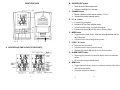
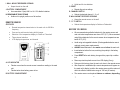
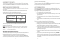
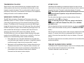
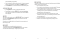
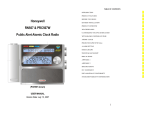
TABLE OF CONTENTS
Honeywell
Wireless In/Out Thermometer
INTRODUCTION
3
PRODUCT OVERVIEW
4
BEFORE YOU BEGIN
8
BATTERY INSTALLATION
9
LOW BATTERY WARNING
10
GETTING STARTED
10
PLACEMENT OF THE UNITS
11
REMOTE AND INDOOR TEMPERATURE
11
MAXIMUM AND MINIMUM READINGS
11
LOST COMMUNICATION
12
TRANSMISSION COLLISION
13
WWVB RADIO CONTROLLED TIME
13
ATOMIC CLOCK
14
TIME AND CALENDAR DISPLAY MODES
14
MANUAL SETTINGS
15
CLOCK ALARMS
15
SNOOZE
17
BACKLIGHT
17
PRECAUTIONS
18
TROUBLESHOOTING
19
SPECIFICATIONS
20
FCC STATEMENT
21
DECLARATION OF CONFORMITY
22
STANDARD WARRANTY INFORMATION
23
(TE219ELW)
USER MANUAL
2
INTRODUCTION
Thank you for selecting the Honeywell Wireless In/Out Thermometer. This
device combines precise time keeping with monitoring and displaying the
weather conditions from up to three remote locations.
In this package you will find:
• One main unit (receiver)
• One remote sensor (transmitter) TS13C
• One User Manual
Please keep this manual handy as you use your new item. It contains practical
step-by-step instructions, as well as technical specifications and precautions
you should know.
3
PRODUCT OVERVIEW
MAIN UNIT
FEATURES
•
•
•
•
Time automatically sets to the US Atomic Clock
12 or 24 hours Time Format
Dual crescendo Time Alarm with Snooze
Day of the week displayed in English, Spanish, French, German and
Italian
•
Wireless Reception of the Temperature from the Remote Sensor to the
Main Unit from up to 100 feet (30 meters) away
•
Multi-Channel Capability to Monitor Temperature in up to 3 Remote
Locations
•
•
•
•
•
Minimum and maximum memory for indoor and remote temperature
Indoor and Remote Temperature display
Programmable Ice Warning Alarm
Low Battery Indicators
Enhanced Blue Backlight
3
4
FRONT/REAR VIEW
B. SNOOZE/LIGHT button
• Stops the clock’s alarm temporarily
• Activates a backlight for 5 seconds
C. CHANNEL button
I
B
• Recalls a different remote sensor reading – 1,2 or 3
• Activates the remote channels search
D. UP ( ▲) button
A
• Increases the parameters
• Activates US Time Zone selection mode
• Activates manual search for atomic time signal
• Enables time alarms (W) and (S) and Ice Warning Alarm
E. MODE button
H
C
G
•
D F
E
J
A. WEATHER AND TIME IN EASY-TO READ DIGITS
K
Toggles between time modes - time with seconds and time with the
day of the week
• Activates clock’s manual programming mode
F. DOWN ( ▼) button
• Decreases the parameters
• Activates manual remote channels search
• Disables time alarms (W) and (S) and Ice Warning Alarm
G. ALARM ON/OFF button
•
Allows toggling between the calendar display and three time alarm
modes
• Allows programming available alarms
H. MEM button
5
•
Toggles between current, minimum, maximum readings of the indoor
and remote temperature
•
Clears the temperature memory
5
6
I. WALL- MOUNT RECESSED OPENING
• Keeps the unit on the wall
J. BATTERY COMPARTMENT
• Accommodates 2 (two) UM-3 or AA 1.5V alkaline batteries
K. REMOVABLE TABLE STAND
•
Holds unit in upright position on a flat surface
Remote temperature transmission to the main unit via 433 MHz
frequency
Case can be wall mounted using built-in hanger
Selection of the temperature display in Celsius or Fahrenheit
Three channel selection
LCD displays temperature, and channel
A. LED INDICATOR
•
• Selects the desired channel -1, 2 or 3
E. WALL-MOUNT RECESSED OPENING
•
FEATURES
•
•
•
•
• Resets all previous settings
D. CHANNEL SWITCH
• Keeps the remote sensor on the wall
F. °C/ °F SWITCH
REMOTE SENSOR
•
• Holds two AA-size batteries
C. RESET
Flashes once when the remote sensor transmits a reading to the main
unit.
• Flashes twice when battery power is low.
B. BATTERY COMPARTMENT
7
Selects the temperature display in Celsius or Fahrenheit
BEFORE YOU BEGIN
•
We recommend using alkaline batteries for the remote sensor and
main unit when temperatures are above 32°F (0°C). We recommend
using lithium batteries for the remote sensor when temperatures are
below 32°F (0°C).
•
Avoid using rechargeable batteries. (Rechargeable batteries cannot
maintain correct power requirements).
•
•
ALWAYS install batteries in the remote sensor before the main unit.
Insert batteries before first use, matching the polarity in the battery
compartment
•
Press RESET after each battery change with a paper clip or similar
tool.
•
•
•
Remove protective plastic screen from LCD display (if any).
During an initial setup, place the main unit close to the remote sensor.
After reception is established (the remote temperature will appear on
the main unit’s display), position the remote sensor and the main unit
within the effective transmission range of 100 feet (30 meters).
•
The remote sensor can be placed indoors or outdoors, depending
7
8
on the area where the temperature is intended to be measured. If
you intend measuring outdoor elements, place remote sensor outdoors
• The main unit must be placed indoors.
NOTE:
1. Avoid pressing any buttons on the main unit before the remote readings
are displayed.
2. The effective operating range may be influenced by the surrounding building
materials and how the receiver and transmitter are positioned.
3. Place the remote sensor so that it faces the main unit (receiver), minimizing
obstructions such as doors, walls, and furniture.
4. Though the remote sensors are weather-resistant, they should be placed
away from direct sunlight, rain or snow. The best suggested location for the
remote sensor for outdoors is under the eave on the north side of the building.
NOTE: When the temperature falls below freezing, the batteries in the
outdoor remote sensor may have reduced voltage supply and a shorter
effective range. We recommend using lithium batteries at temperatures of
32°F (0°C) and below.
polarities shown in the battery compartment.
•
•
Replace the battery compartment door and secure the screws.
Secure the remote sensor in the desired location.
MAIN UNIT
•
•
Remove the battery compartment door.
Install 2 batteries (UM-3 or “AA” size 1.5V) matching the polarity as
shown in the battery compartment.
•
Replace the battery compartment door.
LOW BATTERY WARNING
A low-battery indicator [
] will appear next to the indoor or remote data
reading line of the main unit warning that the corresponding batteries need
replacement.
GETTING STARTED
WEATHER DISPLAY
•
Remove the screws from the battery compartment with a small Phillips
screwdriver.
After batteries are installed; remote sensor will transmit temperature data at 45
second intervals. The main unit may take up to two minutes to receive the initial
readings. Upon successful reception, remote temperature will appear on the
top line of the main unit’s display (the default remote channel is channel one).
The main unit will automatically update readings at 45-second intervals.
After communication between the main unit and remote sensor has been
established, secure the remote sensor in the desired location.
•
Set the channel. The switch is located in the battery
compartment. Channel 1 is typically selected if only one remote sensor
is being used.
If no signal is received from the remote sensor within two minutes, dashes [- - -]
will be displayed. Press and hold the DOWN (T) button on the main unit for
two seconds to initiate another signal search.
•
Install 2 “AA” size alkaline batteries (not included) matching the
BATTERY INSTALLATION
REMOTE SENSOR
NOTE: Install the batteries; select the channel and temperature in °C or °F
before mounting the remote sensor.
9
9
10
PLACEMENT OF THE UNITS
The main unit can be placed on any flat surface indoors. The remote sensor
can be placed indoors or outdoors, on a flat surface or mounted on the wall.
temperature and humidity display.
To clear the memory, press and hold MEM (memory) button for two seconds
and all previously stored readings will be erased.
REMOTE AND INDOOR TEMPERATURE
LOST COMMUNICATION
The remote temperature information line is located on the top line of the main
unit’s display.
The wave icon is located above the remote channel number indicates the
reception status from the corresponding remote sensor.
There are three following types of the reception status may be displayed:
If the main unit display line for the remote sensor reading goes blank, press
and hold DOWN (▼) button for 2 seconds to begin a new signal search. If the
signal still isn’t received, please make sure that:
•
•
The remote sensor is in its proper location.
The distance between main unit and remote sensor(s) is not over 100
feet (30 meters)
The unit is in a searching
mode.
•
The path between units is clear of obstacles. Shorten the distance if
necessary.
Temperature reading is
securely registered.
•
No signals detected.
---
The indoor temperature with the icon IN is located below the remote
temperature information line.
NOTE: If the indoor or remote temperature goes above or below operating
range stated in specifications, the main unit’s display ( weather) will show
dashes “- - -” on the corresponding line.
Fresh batteries are installed correctly in both remote sensor and main
unit.
If there is no reception, please perform the following steps:
•
•
Bring the main unit and remote sensor close together.
Remove four (4) small screws from the back of the remote sensor with
small Phillips screwdriver, and open the battery compartment.
•
Remove the batteries from the battery compartment and reinstall them
in the same manner. Remote sensor LED indicator will flash showing
transmission of the signal.
•
Remove the batteries from the main unit and reinstall them in the same
manner.
•
On the main unit select the same channel number using CHANNEL
button as set on the remote sensor. The remote temperature appeared
on the main unit’s display will show that transmission is being received
successfully.
MAXIMUM AND MINIMUM READINGS
The maximum and minimum record of the indoor and remote temperature will
be automatically stored in the memory of the main unit (receiver).
To display the minimum, maximum or the current reading press MEM button.
If no button is pressed for the next 15 seconds, the unit will return to the current
11
11
12
TRANSMISSION COLLISION
ATOMIC CLOCK
Signals from the other household devices such as wireless doorbells, home
security systems, and entry control, may interfere with this product or cause
temporary reception interruption. This is normal and will not affect the general
performance of the product. The transmission and reception of the temperature
readings will resume once the interference subsides.
Immediately after establishing communication between the main unit and
remote sensor, the atomic time signal receiver will open and start to search for
the atomic time signal. The search usually takes between 5-8 minutes.
NOTE: Do not press any buttons on the main unit during auto search as it
may interrupt product’s operation, and you will need to start set up
WWVB RADIO CONTROLLED TIME
procedure again.
Once the atomic time signal is received, the date and time will be set
The NIST (National Institute of Standards and Technology) radio station
(WWVB) is located in Ft. Collins, Colorado. It transmits an exact time signal
continuously throughout the most of the continental United States at 60 KHz
frequency. The Wireless In/Out Thermometer can receive this WWVB signal
through the internal antenna from up to 2,000 miles away. Due to the nature of
the Earth’s ionosphere, reception can be limited during the daylight hours. The
radio controlled clock will search for an alternate station that receives the
atomic time signal from the NIST Atomic clock in Boulder, Colorado.
The WWVB tower icon on the unit’s display will flash indicating a radio signal
reception from the WWVB station. If the tower icon is not fully lit, or if the time
and date are not set automatically, please consider the following:
•
During night-time hours, atmospheric disturbances are typically less
severe and radio signal reception may improve. A single daily reception
is sufficient enough to keep the clock accuracy within 1 second.
•
Make sure the unit is positioned at 8 feet (2 meters) distance from any
interference source such as a TV, computer monitor, microwave, etc.
•
Within concrete wall rooms such as basements or office buildings, the
received signal may be weakened. Always place the Weather
Forecaster near the window for better reception.
13
automatically, and the [ ] icon will appear.
NOTE: It is necessary to set your Time Zone, having in mind that the
default zone is a US Pacific Standard Time (PST). (Refer to MANUAL
SETTINGS section)
If the time signal has not been received in 8 minutes, you may use the MODE
button to set the time and date manually. (Refer to the MANUAL SETTINGS
section).
After the clock is set manually, place the main unit by the window for the better
reception. The atomic clock receiver is programmed that it will continue to
search for the atomic time signal daily for every hour between 1:00 am and
4:30 am.
Once the time signal has been successfully received, the time and date will be
updated automatically.
TIME AND CALENDAR DISPLAY MODES
The Wireless In/Out Thermometer displays current time in two display modes –
in hour-minutes-seconds format and in hour-minutes-day.
The date is displayed in month-date format.
13
14
MANUAL SETTINGS
subsequent days
It is necessary to set the desired US TIME ZONE.
TIME ZONE
•
Press MODE button once so that the Day of the Week abbreviation is
displayed to the right of the time; for example: pm 2:37tu
•
Select the Time Zone by pressing and holding UP ( ▲) button for 3
seconds
•
Keep holding UP ( ▲) button until the desired US Time Zone (Pacific,
Mountain, Central or Eastern) is highlighted on the display’s US map,
located to the right of the time display and above the day of the week
•
If Ice Warning Alarm ( PRE-AL) is activated, in will sound at the set
time and alarm icon will flash once the remote temperature for Channel
One (1) will reach 32°F(0°C) and below
NOTE: Ice Warning Alarm can be set only if one or both - Weekday or
Single alarm - are programmed.
SETTING THE WEEKDAY (W) AND SINGLE DAY (S) ALARMS
•
Press ALARM button once to enter into the alarms setting mode. The
default alarm is a Weekday alarm (W). The abbreviation “OFF” with a
letter “W” next to it will be displayed, if the alarm has not been set
previously
• Release the UP (▲) button. The Time Zone is set
CLOCK
•
Press and hold MODE button for 3 seconds: the year will flash. Press
UP (▲) or DOWN (▼) to change flashing digits.
•
Press and hold ALARM button for two seconds. The hour digit will
flash
•
After the year is set, press MODE button to confirm and move to the
next parameter (month)
•
Continue setting month, date, hour, minutes, language for the day of
the week and temperature in Fahrenheit or Celsius
•
•
•
•
•
Press MODE for the last time to return to the time of day with seconds,
after the last parameter is set
Adjust the hour using UP ( ▲) or DOWN ( ▼) buttons
Press ALARM button again. The minute digits will flash
Adjust the minutes using UP (▲) or DOWN (▼) buttons
Press ALARM button again to confirm and the weekday alarm time will
be set
•
Set Single (S) day alarm if desired in the same manner
CLOCK ALARMS
SETTING THE ICE WARNING ALARM (PRE-AL)
The Wireless In/Out Thermometer has two time alarms – Weekday alarm (W)
and Single day alarm(S) - and one Ice Warning Alarm (PRE-AL).
If Weekday (W) or Single day (S) alarm is set, the Ice Warning Alarm (Pre-AL)
can be programmed.
•
If Weekday (W) alarm is activated, it will sound at the set time and the
alarm icon will flash Mondays through Fridays
•
Press ALARM button once to enter into the Ice Warning Alarm setting
mode. The abbreviation OFF with a PRE-AL next to it will be displayed.
•
If Single (S) day alarm is activated, it will sound at the set time and the
alarm icon will flash only for this specific day and will not activate on
•
Press and hold ALARM button for two seconds. The number 30 will
flash, meaning that if selected, the alarm will sound 30 minutes earlier
15
15
16
than the Weekday or Single alarm.
PRECAUTIONS
•
Select the desired Ice Warning Alarm interval in 15 minutes increments
between 15 and 90 minutes, using UP (▲) or DOWN (▼)buttons
This product is engineered to give you years of satisfactory service if handled
carefully. Here are a few precautions:
•
Press ALARM button to confirm and exit from the alarm setting mode.
•
•
Do not immerse the units in water.
Do not clean the units with abrasive or corrosive materials. They may
scratch the plastic parts and corrode the electronic circuits.
•
Do not subject the product to excessive force, shock, dust, temperature,
or humidity, which may result in malfunctions, shorter lifespan,
damaged batteries, and damaged parts.
•
Do not tamper with the units internal components. Doing so will
invalidate the warranty and may cause damage. These units contain no
user-serviceable parts.
•
•
Use only fresh batteries. Do not mix new and old batteries.
Read the user's manual thoroughly before operating the units.
ACTIVATING THE ALARM
•
•
Press ALARM button to enter into the desired alarm mode.
Press UP (▲) to activate or DOWN (▼) to deactivate desired alarm.
When alarms are activated, the corresponding icons W, S or PRE-AL
will be displayed.
SNOOZE
When the time alarm sounds, press the SNOOZE/LIGHT button to temporarily
stop it. After the SNOOZE/LIGHT is depressed, the time alarm sound will
resume in four minutes.
If the alarm is not disabled after that, it will sound for two more minutes and
then will stop by itself.
BACKLIGHT
The backlight feature is enabled only after the time is set.
To activate the backlight press the SNOOZE/LIGHT button once, and both –
clock and weather station displays - will light up for five seconds.
17
17
18
TROUBLESHOOTING
SPECIFICATIONS
Check here before contacting customer service.
Issue
Symptom
Solution
Main unit
US Atomic Time
signal is not received
Place unit by the window and
keep it there overnight
Remote sensor
Cannot locate remote
sensor
Check batteries
Check location
Press and hold DOWN ( ▼)
button on the main unit to search
for the signal form the remote
sensor
Cannot change the
channel
Press “RESET” after setting the
channel
Cannot change the
C° to F° and back
Press “RESET” after setting C/F
Data does not match
data on the main unit
Initiate manual sensor search
(Press and hold DOWN ( ▼)
button on the main unit)
19
Main Unit
Indoor Temperature
Proposed operating range: 23.0°F to 122.0°F (-5°C to +50°C)
Temperature resolution: 0.2°F (0.1°C)
User-selectable (°F or °C) temperature display
Maximum number of remote sensors: 3 (one included)
RF range: Maximum 100 feet (30 meters)
Readings update interval: every 45 seconds
EL backlight
Low battery indicators – for each remote channel and main unit
Clock
Precise atomic time
4 US Time Zones
12/24 hour time format
Crescendo 4 minutes alarm with 5 minutes snooze
Remote Sensor
Remote Temperature
Proposed operating range with alkaline batteries:
-4°F to + 158°F (-20°C to + 70°C)
Proposed operating range with lithium batteries:
-38.8°F to +158°F (-38.8°C to + 70°C)
Temperature resolution: 0.1°C/0.2°F
RF Transmission Frequency: 433 MHz
Temperature transmission cycle: approximately 45 seconds
Low battery indicator
Wall-mount of Table stand
Power
Main unit: 2 AA size (UM-3) 1.5V batteries (not included)
Remote Sensor: 2 AA size 1.5V batteries (not included)
Dimensions
Main unit: 3.33(L) x 6.19 (H) x 1.11(D) inches
Remote sensor: 2.37(L) x 4(H) x 1 (D) inch
19
20
FCC STATEMENT
DECLARATION OF CONFORMITY
This device complies with Part 15 of the FCC Rules. Operation is subject to the
following two conditions: (1) This device may not cause harmful interference,
and (2) This device must accept any interference received, including
interference that may cause undesired operation.
Warning: Changes or modification to this unit not expressly approved by the
party responsible for compliance could void the user’s authority to operate the
equipment.
NOTE: This equipment had been tested and found to comply with the limits for
a Class B Digital device, pursuant to Part 15 of the FCC Rules. These limits are
designed to provide reasonable protection against harmful interference in a
residential installation. This equipment, installed and used in accordance with
the instructions, may cause harmful interference to radio communications.
There is no guarantee that interference will not occur in a particular installation.
If this equipment does cause harmful interference to radio or television
reception, which can be determined by turning the equipment off and on, the
user is encouraged to improve or correct turning the interference by one or
more of the following measures:
We
Name: Hideki Electronics, Inc.
Address: 7865 SW Mohawk
Tualatin, OR 97062
declare that the product
Product No.: TE219ELW
Product Name: Honeywell Wireless In/Out Thermometer
Manufacturer: Hideki Electronics Ltd.
Address: Unit 2304-06, 23/F Riley House, 88 Lei Muk Road, Kwai Chung, New
Territories, Hong Kong
is in conformity with Part 15 of the FCC Rules. Operation is subject to the
following two conditions:
This device may not cause harmful interference.
This device must accept any interference received, including interference that
may cause undesired operation.
•
•
•
Reorient or relocate the receiving antenna
Increase the separation between the equipment and receiver.
Connect the equipment to an outlet on a circuit different from that to
which the receiver is connected.
•
Consult the dealer or an experienced radio / TV technician for help.
21
The information above is not to be used as a contact for support or sales.
Please call our Customer Service (refer to the Standard Warranty
Information) for all injuries instead.
21
22
STANDARD WARRANTY INFORMATION
This product is warranted from manufacturing defects for one year from date of
retail purchase. It does not cover damages or wear resulting from accident,
misuse, abuse, commercial use, or unauthorized adjustment and repair.
Note that online product registration is required to ensure valid warranty
protection.
To register your product, go to our Company website at:
www.honeywellweatherstations.com. Click Online Product Registration under
the Customer Service menu.
Should you require assistance with this product and its operation, please
contact our Customer Service at 1(866) 443 3543.
Please direct all returns to the place of the original purchase. Should this not be
possible, contact Hideki Customer Service for assistance and to obtain a
Return Merchandise Authorization (RMA).
Returns without a return authorization will be refused. Please retain your
original receipt as you may be asked to provide a copy for proof of purchase.
Hideki Electronics, Inc. reserves the right to repair or replace the product at our
option.
Copyright (2005) Hideki Electronics Inc. All Rights Reserved. The Honeywell
Trademark is used under license from Honeywell Intellectual Properties Inc.
Honeywell International Inc. makes no representations or warranties with
respect to this product.
All user manual contents and information are subject to change.
23
23