1
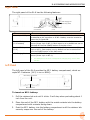
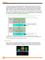
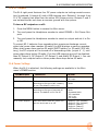
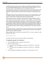
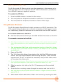
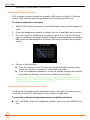
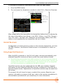
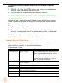
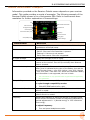
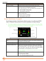
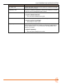
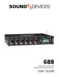
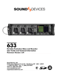
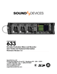
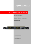
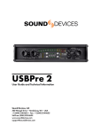
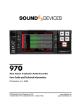
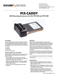
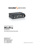
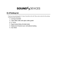
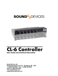
®
SL-6
Powering and Wireless System for the 688
User Guide
Legal Notices
Product specifications and features are subject to
change without prior notification.
Manual Conventions
Symbol
>
This symbol is used to show the order
in which you select menu commands
and sub-options, such as: Main Menu
> Audio indicates you press the Menu
button for the Main Menu, then scroll to
and select Audio by pushing the Control
Knob.
+
A plus sign is used to show button or
keystroke combinations.
Copyright © 2015 Sound Devices, LLC.
All rights reserved.
This product is subject to the terms and conditions
of a software license agreement provided with the
product, and may be used in accordance with the
license agreement.
This document is protected under copyright law. An
authorized licensee of this product may reproduce
this publication for the licensee’s own personal use.
This document may not be reproduced or distributed, in whole or in part, for commercial purposes,
such as selling copies or providing educational services or support.
This document is supplied as a technical guide. Special care has been taken in preparing the information
for publication; however, since product specifications
are subject to change, this document might contain
omissions and technical or typographical inaccuracies. Sound Devices, LLC does not accept responsibility for any losses due to the user of this guide.
Trademarks
The “wave” logo and USBPre are registered
trademarks;
FileSafe,
PowerSafe,
SuperSlot,
MixAssist, QuickBoot, and Wave Agent are trademarks of Sound Devices, LLC. Mac and OS X are
trademarks of Apple Inc., registered in the U.S. and
other countries. Windows and Microsoft Excel are
registered trademarks of Microsoft Corporation in
the U.S. and other countries. All other trademarks
herein are the property of their respective owners.
FCC Notice
Description
For instance, Ctrl+V means to hold the
Control key down and press the V key
simultaneously. This also applies to
other controls, such as switches and
encoders. For instance, MIC+HP turn
means to slide and hold the MIC/TONE
switch left while turning the Headphone
(HP) encoder. METERS+SELECT means
to hold the METERS button down as you
press the SELECT encoder.
i
A note provides information and important related recommendations. The
text for notes also appears italicized in
a different color.
⚠
A cautionary warning about a specific
action that could cause harm to you,
the device, or cause you to lose data.
Follow the guidelines in this document
or on the unit itself when handling electrical equipment. The text for cautionary notes also appears in a different
color, bold and italicized.
SL-6 User Guide • Rev 1-C • August 21, 2015
This device complies with part 15 of the FCC Rules.
Operation is subject to the following two conditions:
(1) This device may not cause harmful interference,
and (2) This device must accept any interference
received, including interference that may cause
undesired operation.
FCC Part 15.19(a)(3)
www.sounddevices.com
[email protected]
This document is distributed by Sound Devices, LLC
in online electronic (PDF) format only. E-published in
the USA.
Sound Devices, LLC
E7556 Road 23 and 33
Reedsburg, Wisconsin USA
Direct:+1 (608) 524-0625
Toll Free: (800) 505-0625
Fax: +1 (608) 524-0655

Revision History
This table provides the revision history of this guide.
Rev#
Date
Description
1-A
June 2015
Initial Official Publication
1-B, 1-C
Aug 2015
Added & revised section on “Automatic Receiver Output Setup” on page 14.
3
SL-6 User’s Guide
4

Table of Contents
SL-6 Powering and Wireless System
Front Panel. . . . . . . . . . . . . . . . . . . . . . . . . . . . . . . . . . . . . . 6
Right Panel. . . . . . . . . . . . . . . . . . . . . . . . . . . . . . . . . . . . . . 7
Left Panel. . . . . . . . . . . . . . . . . . . . . . . . . . . . . . . . . . . . . . . 7
Powering with the SL-6. . . . . . . . . . . . . . . . . . . . . . . . . . . 8
Power Screen. . . . . . . . . . . . . . . . . . . . . . . . . . . . . . . . . . . . 8
SL-6 DC Outputs . . . . . . . . . . . . . . . . . . . . . . . . . . . . . . . . . 9
SL-6 Power Settings . . . . . . . . . . . . . . . . . . . . . . . . . . . . . . 9
Using Antenna Distribution. . . . . . . . . . . . . . . . . . . . . . . 10
Using Wireless Receivers . . . . . . . . . . . . . . . . . . . . . . . . .
Selecting a Wireless Source. . . . . . . . . . . . . . . . . . . . . . .
Accessing the Receiver Overview Screen. . . . . . . . . . . .
Unislot Receivers. . . . . . . . . . . . . . . . . . . . . . . . . . . . . . . .
Using SuperSlot Receivers. . . . . . . . . . . . . . . . . . . . . . . .
Automatic Receiver Output Setup. . . . . . . . . . . . . . . . .
Receiver Details Screen - Example A. . . . . . . . . . . . . . . .
Receiver Details Screen - Example B. . . . . . . . . . . . . . . .
11
12
12
13
13
14
15
16
SL-6 Specifications
Powering. . . . . . . . . . . . . . . . . . . . . . . . . . . . . . . . . . . . . . 18
Antenna Distribution. . . . . . . . . . . . . . . . . . . . . . . . . . . . 19
Physical. . . . . . . . . . . . . . . . . . . . . . . . . . . . . . . . . . . . . . . . 19
5
SL-6 Powering and Wireless System
The SL-6 offers built-in NP-1 battery
powering for the 688 mixer, slot
receivers, plus four additional DC
outputs for external peripherals, as well
as built-in antenna distribution.
Using Sound Devices’ proprietary
SuperSlot™ interconnection standard,
the SL-6 offers all powering, audio
interconnection and control needed for
SuperSlot-compatible receivers.
LL The SL-6 attaches to the top panel
of the 688. Instructions for attaching
the SL-6 to your mixer is provided in
the SL-6 Quick Start Guide, which is
shipped with the accessory. It is also
available as a PDF download from the
Sound Devices website.
Topics in this section include:
Front
Panel
Right
Panel
Left
Panel
Powering
with the SL-6
Power
Screen
SL-6
DC Outputs
SL-6
Power Settings
Using
Antenna Distribution
Using
Wireless Receivers
Selecting
a Wireless Source
Accessing
the Receiver Overview Screen
Unislot
Receivers
Using
SuperSlot Receivers
Automatic
Receiver Output Setup
Receiver
Details Screen - Example A
Receiver
Details Screen - Example B
Front Panel
The front panel of the SL-6 has the following features:
Antenna Connector A
Antenna Distribution lead (A)
Receiver Slot 1
Receiver Slot 2
Antenna Distribution lead (B)
Feature
Receiver Slot 3
Antenna Distribution lead (A)
Antenna Connector B
Antenna Distribution lead (B)
Description
Receiver Slots
Each slot accepts one (single- or dual-channel) SuperSlot or unislot
receiver. The connection provides power to the receiver and connects
the receiver’s audio output directly to the 688.
Antenna Distribution
leads
SMA connectors with right-angle adapters are used to connect receivers to the SL-6 antenna distribution system.
Antenna Connectors
BNC connectors are used for attaching external antennas to the SL-6
antenna distribution system.
LL
Use BNC to SMA adapters, included with the SL-6, for antennas with
SMA connectors.
6
SL-6 POWERING AND WIRELESS SYSTEM
Right Panel
The right panel of the SL-6 has the following features:
Hirose 4-pin DC Input
USB Charging Port
Power only (5V DC)
Coaxial DC Outputs
(12 V Isolated)
Feature
Coaxial DC Outputs
(12 V)
Description
Hirose 4-pin DC Input Hirose 4-pin DC input for powering the SL-6 and 688. Power must
be attached to this connector or an NP-1 battery must be inserted to
power the SL-6 and 688.
Coaxial DC Outputs
(12 V Isolated)
Isolated 12 V DC outputs that draw from the active SL-6 power
source (Hirose 4-pin or NP-1). Each output is on by default but can be
switched off from the POWER section of the Main menu.
Coaxial DC Outputs
(12 V)
12 V DC outputs that draw from the active SL-6 power source (Hirose
4-pin or NP-1). Each output is on by default but can be switched off
from the POWER section of the Main menu.
USB Charging Port
Standard USB 5 V DC output that draws from the active SL-6 power
source (Hirose 4-pin or NP-1).
LL
The USB port on the SL-6 is designed for charging only, not for data
transfer.
Left Panel
The left panel of the SL-6 provides the NP-1 battery compartment, which accepts NP-1 batteries (14 V, Li-ion or NiMH).
NP-1 battery compartment
Metal retainer tab
To insert an NP-1 battery:
1. Pull the retainer tab out until it clicks. It will stop when protruding about 1
inch from the unit.
2. Place the end of the NP-1 battery with the metal contacts into the battery
compartment with contacts facing down.
3. Push the NP-1 battery into the battery compartment until the retainer tab
securely snaps over the end of the battery.
7
User Guide
Powering with the SL-6
The SL-6 features two power inputs: NP-1 battery and external DC. The SL-6,
its attached receivers, the 688 (and CL-6, if connected), and any devices powered from the SL-6 DC outputs require one of these power sources to operate.
When both SL-6 power sources are depleted or disconnected, the SL-6 PowerSafe™ battery will keep the SL-6 and attached devices powered for 10 seconds
while recording is stopped. If any power source is attached to the 688’s external
DC input, or if internal AA batteries are present, the 688 (and CL-6, if attached)
will continue to operate using those power sources.
LL Power sources connected directly to the 688 (external DC or the internal AA batteries) will not power the SL-6 or any attached peripheral devices.
When activated, the SL-6 (including wireless receivers and any equipment connected to the SL-6 DC outputs) will be
shut down.
When activated, the 688 (and CL-6 if
attached) will be shut down.
When the SL-6 is attached, the battery icon on the Main screen will display NP
or EX to indicate which power source is active.
Power Screen
When the SL-6 is attached to the 688, the mixer’s Power screen displays the
voltage level of the attached NP-1 battery, the SL-6 external DC power source,
and the SL-6 PowerSafe battery, in addition to the 688’s own power sources.
8
SL-6 POWERING AND WIRELESS SYSTEM
SL-6 DC Outputs
The SL-6 right panel features four DC power outputs via locking coaxial connectors (numbered 1 through 4) and a USB charging port. Outputs 1 through 4 are
12 V DC outputs that draw from the active SL-6 power source. Outputs 1 and 2
are isolated and do not share a common ground with the system.
To turn a DC output on or off:
1. Press the MENU button to access the Main menu.
2. Turn and press the Headphone encoder to select POWER > SL-6 Power Outputs.
3. Turn and press the Headphone encoder to select an output and set it to On
or Off.
To protect NP-1 batteries from exceeding their maximum discharge current,
when total power draw reaches 45 watts, the 688 displays a warning message.
When total power draw reaches 50 watts (SWIT battery) or 53 watts (IDX battery), the DC outputs will be turned off in descending order (output 4 - 1) until
power draw drops below 45 watts. First the USB charging port will be disabled,
then DC Output 4, DC Output 3, DC Output 2, and finally DC Output 1. You can
manually turn outputs back on when power draw drops below 45 watts.
SL-6 Power Settings
When the SL-6 is attached, the following settings are available in the Main
menu’s POWER section.
Sub-Menu Name
Description
Options
SL-6 Primary Source
Selects primary power source.
• NP-1
• DC Input
SL-6 NP-1 DC Ref
Calibrates the power level indicator
according to the type of NP-1 battery
in use. The default is 14V Li-ion.
• 14V Li-ion
• NiMH
SL-6 DC Input Ref
Calibrates the power level indicator
according to the type of external DC
source. The default is 12V Ext DC.
• 12V Ext DC
• NiMH
• Expanded NiMH
• 12V Lead Acid
• 14V Li-ion
• Full Range
SL-6 Power Outputs
Sub-menu where each DC power output can be turned on or off.
• Output 1 (12V Isolated)
• Output 2 (12V Isolated)
• Output 3 (Battery)
• Output 4 (Battery)
• USB Charging Port
9
User Guide
Using Antenna Distribution
Two BNC antenna connections (A and B) are provided for attaching antennas
to the antenna distribution system. Antennas with an SMA connection may be
used with a BNC to SMA adapter, which is included with the SL-6.
The antennas on the SL-6 provide improved diversity performance due to wider
spacing than those directly mounted on the receivers. This can reduce the instances of signal dropouts due to destructive cancellation of reflecting RF signals.
Good performance will be obtained when antennas are mounted directly to the
SL-6 BNC connectors. Quarter wave whip antennas are typically used in this
scenario with the SL-6 housing providing the reference plane.
Better performance will usually be observed with a higher elevation of the receive antenna. This can provide a more direct line of sight to the transmitter
which improves signal strength. Shoulder mounted antennas are one example.
Care should be used with antenna selection in this scenario. Some antennas,
such as quarter wave (also known as quarter wave whip antennas), require a
ground plane (metallic reflective surface usually perpendicular to the antenna).
Others, such as a half wave antenna and log periodic antenna (Also referred
to as paddle antenna), can be remotely mounted and do not require a ground
plane.
For best performance, Sound Devices recommends directional remote antennas.
Independent 12 volt antenna bias for powering active antennas is provided at
each SL-6 antenna BNC connector.
Many variables are involved with a successful RF link. As such, results for each
operation may vary.
Antenna Bias Power
If needed, 12V bias power may be provided to each antenna.
To supply bias power to an antenna:
1. Press the MENU button to access the Main menu.
2. Do one of the following:
XX Turn and press the Headphone encoder to select SL-6 > Antenna A
Power.
XX Turn and press the Headphone encoder to select SL-6 > Antenna B
Power.
3. Turn and press the Headphone encoder to turn bias power on or off.
10
SL-6 POWERING AND WIRELESS SYSTEM
Radio Frequency (RF) Filter
The SL-6 provides RF filtering which can allow operation in the presence of interfering signals such as cell phones and TV stations. Selection is provided for
four different frequency ranges of operation.
To enable the RF filter:
1. Press the MENU button to access the Main menu.
2. Turn and press the Headphone encoder to select SL-6 > Antenna Filter.
3. Turn and press the Headphone encoder to select a filter range.
Using Wireless Receivers
The SL-6 supports SuperSlot and unislot receivers on a DB-25 connection. The
SL-6 receiver slots provide power and audio connection to both types of receivers. Additionally, SuperSlot receivers can be controlled from the 688 interface.
To connect antennas to the SL-6:
XX Connect each antenna directly to each BNC Antenna Connector on the SL-6.
To connect a receiver to the SL-6:
LL Mounting procedures for receiver models may vary. Refer to the receiver manufacturer’s documentation for your receiver and follow the specific mounting instructions.
⚠⚠ The Lectrosonics SRb5P can not be connected to slot 1 of the SL-6. Using
the blue spacer (Provided with the receiver), the SRb5P can be connected
to slot 2 or 3.
1. Power off the 688.
2. The SL-6 ships with rubber slot protectors that hold the SMA antenna connectors with right-angle adapters secure during transport. These must be
removed prior to use, so remove the connector, then pull the rubber cover
off to expose the chosen slot.
LL Do not discard protectors; Sound Devices recommends storing the connectors with
their right-angle adapters in the rubber slot protectors when not in use.
3. Slide the receiver into slot on the SL-6. If necessary, use the provided
spacer.
4. Screw the four mounting screws through the receiver and into the SL-6.
⚠⚠ Use only the screws provided with the receiver. Longer screws can damage the SL-6.
5. Attach each antenna distribution lead to the receiver by screwing the SMA
11
User Guide
connector on both sides of the receiver.
Selecting a Wireless Source
SL-6 wireless receiver outputs are routed to 688 inputs via the SL-6 Routing
screen. One wireless receiver output can be routed to one 688 input.
To route a receiver to an input:
1. Slide the PFL switch to access the Input Settings screen for the respective
input.
2. Press the Headphone encoder to display the list of available input sources.
3. Turn and press the Headphone encoder to select SL-6. The SL-6 Routing
screen is displayed. Wireless receiver outputs are represented as rows and
688 inputs are represented as columns. Blue boxes indicate active assignments.
4. Do any of the following:
XX Turn the Select encoder to move the orange highlight vertically and
press the encoder to activate or deactivate the route.
XX Turn the Headphone encoder to move the orange highlight horizontally
and press the encoder to activate or deactivate the route.
LL When a wireless receiver output is routed to a 688 input, that channel’s input
source is set to SL-6. When a wireless receiver output is not routed from a 688
input, that channel’s input source is set to OFF.
Accessing the Receiver Overview Screen
The Receiver Overview screen displays summary information for all receivers
connected to the SL-6. Information on this screen is read-only.
To access the Receiver Overview screen via button shortcut:
XX HP + METERS: Press the Headphone encoder, then press the METERS button.
12
SL-6 POWERING AND WIRELESS SYSTEM
To access the Receiver Overview screen from the Main menu:
1. Press the MENU button.
2. Turn and press the Headphone encoder to select SL-6 > Receiver Overview.
Receiver number
Transmitter battery level
688 channel
Receiver frequency
RF signal strength
Pre-fade level
Highlighted receiver
When supported by the transmitter, the transmitter battery level is indicated by
the color of the battery icon: Green = over 50%, Yellow = over 20%, Orange =
over 10%, Red = less than 10%. Whenever the transmitter battery level information is not supported by the transmitter, the icon is black.
Unislot Receivers
Configuration of unislot receivers is done on the receivers themselves, not from
the 688; therefore, the Receiver Details screen is not available for unislot receivers.
Using SuperSlot Receivers
When the 688 is powered on, the SL-6 will power receivers automatically, and
attached SuperSlot receivers will boot up with their panel buttons locked.
LL Sound Devices recommends, if the 688 is powered on, you do not power down attached SuperSlot receivers. If SuperSlot receivers are powered down manually (by
unlocking the receivers’ front panel buttons), the receivers will not be recognized
until they are powered on manually and the 688 is rebooted.
SuperSlot receivers can be configured from the 688 user interface. Detailed
information for each attached SuperSlot receiver is displayed on the 688 via a
Receiver Details screen. Adjustments to SuperSlot receivers may be made from
this screen.
The screen’s title will show the type or model of the receiver. Based on your
receiver, information on screen could vary; refer to the receiver manufacturer’s
documentation provided with your receiver(s) for more information.
13
User Guide
To access the Receiver Details screen from the Receiver Overview
screen:
1. METERS + HP: Press the METERS button, then push in the Headphone encoder to access the Receiver Overview screen.
2. Turn and press the Headphone encoder to select a receiver.
LL Use the shortcut HP+PFL(1-6) for direct access to the Receiver Details screen for
each receiver. This bypasses the Receiver Overview screen, showing data for all
slotted receivers.
Receiver tuning is presented uniquely, based on each manufacturer’s receiver
model. Current tuning values are displayed in outlined boxes on the Receiver
Details screen.
To adjust a receiver’s tuning:
1. Access the Receiver Details screen.
2. Turn and press the Headphone encoder to enter editing mode for the selected field. The background color of the field will become blue to indicate editing mode.
3. Turn the Headphone encoder to adjust the value.
4. Press the Headphone encoder to accept the value.
Automatic Receiver Output Setup
When using SuperSlot receivers with the SL-6, some receiver settings are automatically set by the mixer for optimized performance.
These settings include:
Receiver
Lectrosonics SRB
Setting
SETUP > LEVEL = -6
SETUP > PHASE = +
Description
To achieve optimal audio level and to match the
SRB output to the mixer’s input stage for best
dynamic range, the 688 automatically sets the
SRBs gain level to -6, and the phase to +.
There is no reason to manually set the SRB to
any other level. Use the 688’s trim control to
make any necessary adjustments.
Wisycom MCR-42S
The following settings are applied only when all receivers in the SL-6 are
AES-3 compatible:
MENU > Advanced > LINE Mode = AES-3
MENU > Advanced > Edit RX1/RX2 > Audio Out > AES3 max lev = 0 dBFS
MENU > Advanced > Edit RX1/RX2 > Sig. phase = 0°
The following settings are applied whenever some of the receivers in the
SL-6 are not AES-3 compatible:
MENU > Advanced > LINE Mode = Analog
MENU > Advanced > Edit RX1/RX2 > Audio Out > LINE max lev = 0 dBU
MENU > Advanced > Edit RX1/RX2 > Sig. phase = 0°
14
SL-6 POWERING AND WIRELESS SYSTEM
Receiver Details Screen - Example A
Information provided on the Receiver Details screen depends on your receiver
model. This guide provides a couple of examples. The following example of the
Receiver Details screen is for a Lectrosonics SRb. Refer to Lectrosonics documentation for further explanation of these settings.
Title
688 channel information
Pilot tone status
RF signal strength
Antenna phase
Pre-fade level
Transmitter battery level
Frequency
Block & Tx Switch
Tuning group
Receiver settings
Compatibility mode
Screen Element
Description
Title
Screen’s title displays the number of the receiver followed by the
manufacturer and model name.
Pilot tone status
Different letters are displayed based on status of pilot tone.
• Solid P: Pilot tone from transmitter is present.
• Flashing P: Pilot tone is not present.
• Solid, lower-case b: Pilot tone is bypassed.
RF signal strength
Displays the strength of the RF signal.
Antenna phase
The antenna icon is displayed when Switching Diversity mode
is active on the receiver. Icon will flip vertically when antenna
phase is inverted.
Transmitter battery level
Displays the level of the transmitter’s battery. The transmitter
battery level is indicated by the color of the battery icon and the
level of the bar. Green = over 50%, Yellow = over 20%, Orange
= over 10%, Red = less than 10%. When the transmitter battery
level information is not supported, the icon is black.
LL
Compatibility
This information is only provided when supported and supplied by
the transmitter.
Displays the current compatibility mode of the receiver.
To cycle through compatibility modes:
XX
Slide MIC/TONE switch left or right.
688 channel information
Displays the name and number of the 688 channel to which the
receiver is routed.
Pre-fade level
Displays pre-fade audio level of the receiver’s output on the 688
input to which it is routed.
Frequency
Displays the frequency to which the receiver is currently tuned.
Whole number and decimal number are adjusted independently.
Decimal adjustments in .1 (Normal tuning) or .025 increments
(Fine tuning).
To adjust frequency:
XX
Turn and press Headphone encoder.
15
User Guide
Screen Element
Description
Block & Tx Switch
Displays the block number and transmitter switch value.
Tuning
Displays current tuning group. When adjusting frequency, values
will be restricted to the selected tuning group.
“Fine” sets increment to .025, and “Normal” sets increment to .1
To cycle through tuning groups:
XX
Menu
Slide RTN/FAV switch left.
Accesses the receiver’s model-specific settings. Slide RTN/FAV
switch to access menu.
To access receiver’s settings:
XX
Slide RTN/FAV switch right.
Receiver Details Screen - Example B
The following example of the Receiver Details screen is for a Wisycom MCR42.
Refer to Wisycom documentation for further explanation of these settings.
LL This section applies to Wisycom receivers with firmware version 3.5 or later. Wisycom receivers with earlier versions of firmware will be treated as unislot receivers;
therefore, the Receiver Details screen will not be accessible.
Title
RF signal strength
Active antenna
Pre-fade level
Frequency lock
Transmitter battery level
Group
Channel
Receiver settings
Frequency
Screen Element
Description
Title
Screen’s title displays the number of the receiver followed by the
manufacturer and model name.
RF signal strength
Displays the strength of the RF signal.
Active antenna
Displays A or B to indicate which antenna is currently in use.
Transmitter battery level
Displays the level of the transmitter’s battery. The transmitter
battery level is indicated by the color of the battery icon and the
level of the bar. Green = over 50%, Yellow = over 20%, Orange
= over 10%, Red = less than 10%. When the transmitter battery
level information is not supported, the icon is black.
LL
GR:
This information is only provided when supported and supplied by
the transmitter.
Displays the current group number of the receiver.
To set the group number:
XX
16
Turn and press Headphone encoder
SL-6 POWERING AND WIRELESS SYSTEM
Screen Element
Description
Pre-fade level
Displays pre-fade audio level of the receiver’s output on the 688
input to which it is routed.
Frequency lock
Lock icon is visible for channels in which the frequency is locked.
Frequency cannot be adjusted when locked.
CH:
The channel number of the receiver.
To set the channel number:
XX
Menu
Turn and press Headphone encoder
Accesses the receiver’s model-specific settings.
To access receiver’s settings:
XX
Frequency
Slide RTN/FAV switch right
Displays the frequency to which the receiver is currently tuned.
Whole number and decimal number are adjusted independently.
Decimal adjustments in .025 increments. Not adjustable when
frequency is locked.
To adjust frequency:
XX
Turn and press Headphone encoder.
17
SL-6 Specifications
This section provides specifications for
the SL-6 powering and wireless system,
an optional accessory for the 688.
Features and specifications are
subject to change. Visit the Sound
Devices website for the latest product
information.
Topics in this section include:
Powering
Antenna
Distribution
Physical
Powering
Name
Description
External Power Supply
• 10 to 18 V on locking 4-pin Hirose connector
• Pin-4 = (+), Pin-1 = (-)
• Mates with gold Hirose #HR10A-7P-4P (DigiKey# HR110-ND) or
silver Hirose #HR10-7P-4P (DigiKey# HR100-ND) locking connector
PowerSafe
• 10 second power reserve to SL-6, 688 (and CL-6 if connected),
and attached peripherals.
USB Charging port
• 5 V, 2 A max
DC Outputs 1-2
• Locking, coaxial connector
• Isolated
• 12 V, 0.5 A max
DC Outputs 3-4
• Locking, coaxial connector
• 10 to 17 V, 0.5 A max
18
SL-6 SPECIFICATIONS
Antenna Distribution
Name
Description
Antenna impedance
• 50 ohm
Antenna bias voltage
• 12 V @ 200 mA
Antenna filter ranges
• 470-870
• 470-700
• 470-590
• 580-700
MHz
MHz
MHz
MHz
Physical
Name
Description
Dimensions (H x W x D) • 1.4 in x 12.7 in x 5.6 in
• 3.6 cm x 32.3 cm x 14.2 cm
Weight
(without receivers)
• 2 lbs 6 oz
• 1.08 kg
19
User Guide
20
®
Sound Devices, LLC
E7556 Road 23 and 33
Reedsburg, Wisconsin 53959
USA
Phone: +1 (608) 524-0625
Fax: +1 (608) 524-0655
Customer Support
Product Information
Toll Free: (800) 505-0625
For more information about products
and accessories, visit us on the web
at www.sounddevices.com.
[email protected]
http://www.sounddevices.com/support
http://forum.sounddevices.com