1
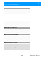
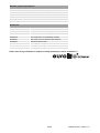
USER MANUAL LED PIXEL MESH 64x64 OUTDOOR KEEP THIS MANUAL FOR FUTURE NEEDS © COPYRIGHT REPRODUCTION PROHIBITED TABLE OF CONTENTS 1 INTRODUCTION ............................................................................................................................................ 3 2 SAFETY INSTRUCTIONS ............................................................................................................................. 4 3 OPERATING DETERMINATIONS................................................................................................................. 6 4 COMPONENTS OF A DISPLAY.................................................................................................................... 7 >> Mounting Elements and Connections of a Display.................................................................................... 8 >> Control Components.................................................................................................................................. 9 Scanning Box............................................................................................................................................. 9 PCI Sending Card.................................................................................................................................... 10 External Sending Card ............................................................................................................................ 10 5 ATTACHMENT............................................................................................................................................. 11 Safety Instructions ................................................................................................................................... 11 6 CONNECTIONS ........................................................................................................................................... 13 >> Example Configuration ............................................................................................................................ 13 >> Connection and Operation of the External Sending Card ....................................................................... 14 >> Installation and Connection of the PCI Sending Card ............................................................................. 15 >> Connection of the Scanning Box ............................................................................................................. 16 >> Connection of the Displays...................................................................................................................... 17 7 LED STUDIO ................................................................................................................................................ 18 >> File Types ................................................................................................................................................ 19 >> Graphics Card Configuration ................................................................................................................... 19 >> Installation................................................................................................................................................ 21 >> Graphical User Interface.......................................................................................................................... 21 Toolbar................................................................................................................................................... 221 Editor ....................................................................................................................................................... 21 >> Program Start .......................................................................................................................................... 23 >> Configuration ........................................................................................................................................... 23 Monitor Settings....................................................................................................................................... 24 Hardware Parameters.............................................................................................................................. 28 Function Test ........................................................................................................................................... 28 >> First Steps to a Show with LED Studio.................................................................................................... 29 Program Window ..................................................................................................................................... 29 Creating a Show and Loading Video ....................................................................................................... 30 Storing Your Show................................................................................................................................... 32 Playing Your Show .................................................................................................................................. 32 8 CLEANING AND MAINTENANCE .............................................................................................................. 33 9 PROBLEM CHART ...................................................................................................................................... 34 10 TECHNICAL SPECIFICATIONS................................................................................................................ 35 This user manual is valid for the article numbers: 80503500, 80503505 2/36 00066677.DOC, Version 1.0 1 INTRODUCTION LED PIXEL MESH OUTDOOR For your own safety, please read this user manual carefully before you initially start-up. You can find the latest update of this user manual in the Internet under: www.eurolite.de Every person involved with the installation, operation and maintenance of this device has to - be qualified - follow the instructions of this manual - consider this manual to be part of the total product - keep this manual for the entire service life of the product - pass this manual on to every further owner or user of the product - download the latest version of the user manual from the Internet Thank you for having chosen a EUROLITE LED Pixel Mesh System. If you follow the instructions given in this manual, we are sure that you will enjoy this device for a long period of time. .............................................................................................................................................................................. 3/36 00066677.DOC, Version 1.0 2 SAFETY INSTRUCTIONS CAUTION! Be careful with your operations. With a dangerous voltage you can suffer a dangerous electric shock when touching the wires! This device has left our premises in absolutely perfect condition. In order to maintain this condition and to ensure a safe operation, it is absolutely necessary for the user to follow the safety instructions and warning notes written in this user manual. Important: Damages caused by the disregard of this user manual are not subject to warranty. The dealer will not accept liability for any resulting defects or problems. If the device has been exposed to drastic temperature fluctuation (e.g. after transportation), do not switch it on immediately. The arising condensation water might damage your device. Leave the device switched off until it has reached room temperature. Please make sure that there are no obvious transport damages. Should you notice any damages on the A/C connection cable or on the casing, do not take the device into operation and immediately consult your local dealer. This device falls under protection-class I. The power plug must only be plugged into a protection class I outlet. The voltage and frequency must exactly be the same as stated on the device. Wrong voltages or power outlets can lead to the destruction of the device and to mortal electrical shock. Always plug in the power plug last. The power plug must always be inserted without force. Make sure that the plug is tightly connected with the outlet. Never let the power-cord come into contact with other cables! Handle the power-cord and all connections with the mains with particular caution! Never touch them with wet hands, as this could lead to mortal electrical shock. Never modify, bend, strain mechanically, put pressure on, pull or heat up the power cord. Never operate next to sources of heat or cold. Disregard can lead to power cord damages, fire or mortal electrical shock. The cable insert or the female part in the device must never be strained. There must always be sufficient cable to the device. Otherwise, the cable may be damaged which may lead to mortal damage. Make sure that the power-cord is never crimped or damaged by sharp edges. Check the device and the power-cord from time to time. If extension cords are used, make sure that the core diameter is sufficient for the required power consumption of the device. All warnings concerning the power cords are also valid for possible extension cords. Always disconnect from the mains, when the device is not in use or before cleaning it. Only handle the power-cord by the plug. Never pull out the plug by tugging the power-cord. Otherwise, the cable or plug can be damaged leading to mortal electrical shock. If the power plug or the power switch is not accessible, the device must be disconnected via the mains. If the power plug or the device is dusty, the device must be taken out of operation, disconnected and then be cleaned with a dry cloth. Dust can reduce the insulation which may lead to mortal electrical shock. More severe dirt in and at the device should only be removed by a specialist. There must never enter any liquid into power outlets, extension cords or any holes in the housing of the device. If you suppose that also a minimal amount of liquid may have entered the device, it must immediately be disconnected. This is also valid, if the device was exposed to high humidity. Also if the device is still 4/36 00066677.DOC, Version 1.0 running, the device must be checked by a specialist if the liquid has reduced any insulation. Reduced insulation can cause mortal electrical shock. There must never be any objects entering into the device. This is especially valid for metal parts. If any metal parts like staples or coarse metal chips enter into the device, the device must be taken out of operation and disconnected immediately. Malfunction or short-circuits caused by metal parts may cause mortal injuries. HEALTH HAZARD! Never look directly into the light source, as sensitive persons may suffer an epileptic shock (especially meant for epileptics)! Keep away children and amateurs! Never leave this device running unattended. .............................................................................................................................................................................. 5/36 00066677.DOC, Version 1.0 3 OPERATING DETERMINATIONS The LED Pixel Mesh 64x64 LED display was specially designed for projection of videos and graphics synchronous to the computer. The modular design allows the horizontal and vertical built-up of large video screens applicable for clubs, stages, shops and various other indoor and outdoor environments. Control is via special PC software and network components. The LED displays and the Scanning Box are allowed to be operated with an alternating voltage of 100-240 V AC, 50/60 Hz. The LED displays, the Scanning Box as well as the power and data cables are protected against dust and water jets (IP 65) and therefore are qualified for indoor and outdoor use. For outdoor use, the installer must always make sure to connect a rubber cable HO5RR-F. All valid instructions concerning the installation of cables outdoors or in the ground must be adhered! The ambient temperature must always be between -10° C and +45° C. Keep away from direct insulation (particularly in cars) and heaters. The maximum relative humidity is 100 % with an ambient temperature of 25° C. This device must only be operated in an altitude between -20 and 2000 m over NN. Do not shake the device. Avoid brute force when installing or operating the device. Before installing the system, make sure that the installation area can hold a minimum point load of 4 times the system's load (e.g. weight 20 kg - point load 80 kg). For overhead use (mounting height >100 cm), always secure the installation with an appropriate secondary safety element (e.g. steel rope). Make sure the area below the installation place is cordoned off when rigging, derigging or servicing the device. Do not connect displays to the mains while they are folded. The F-symbol means: this device can be installed on normal inflammable surfaces. - - -m The symbol determines the minimum distance from lighted objects. The minimum distance between light output and the illuminated surface must be more than the given value. The maximum ambient temperature Ta must never be exceeded. Never use solvents or aggressive detergents in order to clean the device! Rather use a soft and damp cloth. Please consider that unauthorized modifications on the device are forbidden due to safety reasons! If this device will be operated in any way different to the one described in this manual, the product may suffer damages and the guarantee becomes void. Furthermore, any other operation may lead to dangers like shortcircuit, burns, electric shock, lamp explosion, etc. .............................................................................................................................................................................. 6/36 00066677.DOC, Version 1.0 4 COMPONENTS OF A DISPLAY The following describes all the components needed to operate an LED display. Some of the components are used for other EUROLITE products as well. .............................................................................................................................................................................. 7/36 00066677.DOC, Version 1.0 .............................................................................................................................................................................. >> Mounting Elements and Connections of a Display .............................................................................................................................................................................. 8/36 00066677.DOC, Version 1.0 .............................................................................................................................................................................. >> Control Components The LED displays are controlled by a sending card and the light effect software [LED Studio] together with a computer. The computer must be equipped with a Windows operating system and a graphics card with DVI and VGA monitor output. The sending card is available in two versions: as a PCI card and as an external card. Image processing, configuration and setting of control functions is done with the software. The data is transmitted from the computer to the Scanning Box via included patch cable which is also applicable for outdoor use. For connecting the displays, the Scanning Box offers eight data outputs; each of which each connects eight displays in series. This corresponds to a configuration 128 x 128 pixels. In order to build up a large video wall consisting of several displays the Scanning Boxes can also be connected in series by using special accessory cables. .............................................................................................................................................................................. Scanning Box .............................................................................................................................................................................. 9/36 00066677.DOC, Version 1.0 .............................................................................................................................................................................. PCI Sending Card .............................................................................................................................................................................. External Sending Card .............................................................................................................................................................................. 10/36 00066677.DOC, Version 1.0 5 ATTACHMENT Attach the displays at the desired location with the optional mounting brackets. • Always attach the displays using all four attachment points. • Use M8 x 20 screws for the displays. • Use an appropriate dowel/screw combination for attaching the displays to a wall. The displays can be attached to truss systems by applying an appropiate subconstruction. DANGER TO LIFE! Suspended installation by experienced and trained persons only. Incorrect installations are a potential danger, especially if systems are flown above persons. .............................................................................................................................................................................. Safety Instructions Caution! For installation in public or industrial areas, a series of safety instructions have to be followed that this manual can only give in part. The operator must therefore inform himself on the current safety instructions and consider them. The manufacturer cannot be made liable for damages caused by incorrect installations or insufficient safety precautions! 11/36 00066677.DOC, Version 1.0 DANGER TO LIFE! Please consider the EN 60598-2-17and the respective national standards during the installation! The installation must only be carried out by an authorized dealer! The device has to be installed out of the reach of people and should be installed outside areas where persons may walk by or be seated. The installation area for the display has to be built and constructed in a way that it can hold 4 times the weight for 1 hour without any harming deformation. DANGER OF FIRE! When installing the device, make sure there is no highly-inflammable material (decoration articles, etc.) within a distance of min. 0.5 m. The operator has to make sure that safety-relating and machine-technical installations are approved • by an expert before taking into operation for the first time and after changes before taking into operation another time. • by an expert after every four year in the course of an acceptance test. • by a skilled person once a year. IMPORTANT! Overhead rigging requires extensive experience, including (but not limited to) calculating working load limits, installation material being used, and periodic safety inspection of all installation material and the device. If you lack these qualifications, do not attempt the installation yourself, but instead use a professional structural rigger. Improper installation can result in bodily injury and or damage to property. DANGER TO LIFE! Before taking into operation for the first time, the installation has to be approved by an expert! .............................................................................................................................................................................. 12/36 00066677.DOC, Version 1.0 6 CONNECTIONS >> >> Always fasten the locknuts on the connectors in order to ensure compliance with the IP65 protection class. Do not use a network hub or switch to connect the Scanning Box to the sending card. .............................................................................................................................................................................. >> Example Configuration As a reference, this user manual describes the configuration of a video wall of 5 x 10 meters. This setup requires 128 displays and 2 Scanning Boxes and corresponds to a resolution of 128 x 256 pixels. .............................................................................................................................................................................. 13/36 00066677.DOC, Version 1.0 .............................................................................................................................................................................. >> Connection and Operation of the External Sending Card Connect the DVI port of the sending card to the DVI port of the computer via the supplied DVI cable. Connect the USB port of the sending card to the USB port of the computer via the supplied USB cable. Connect the power supply unit to the power input jack [DC 5V] on the sending card and connect the power cable to the power supply unit. Plug the mains plug to a mains outlet. Thus the sending card is powered on and is in standby mode. The [POWER] indicator lights. By disconnecting the unit from the mains it can be switched off. Use the unit only with the supplied power unit. Always disconnect the mains connector when you wish to change connections, move the unit to a different place or if it is not used for a longer period. The computer's graphics card must be configured for use with the sending card ( chapter 7 Graphics Card Configuration). The [SIGNAL] indicator lights when the data link is established. With the buttons [] and [] you can manually adjust the brightness of the displays connected in 16 steps. .............................................................................................................................................................................. 14/36 00066677.DOC, Version 1.0 .............................................................................................................................................................................. >> Installation and Connection of the PCI Sending Card Turn off the computer, disconnect the power plug and remove the case. Take anti-static precautions (e.g. touch a metal object) to avoid damage to the computer. Insert the sending card into a free PCI slot of the computer. Connect the sending card to the computer's power output. Replace the case. Apply power to the computer and start it. Connect the DVI and USB ports of the sending card to the computer's ports via the supplied cables. The computer's graphics card must be configured for use with the sending card ( chapter 7 Graphics Card Configuration). If the green status LED of the sending card is flashing constantly, power supply and data link are established. .............................................................................................................................................................................. 15/36 00066677.DOC, Version 1.0 .............................................................................................................................................................................. >> Connection of the Scanning Box Connect the Scanning Box to a sending card. Connect the data signal input [SIGNAL INPUT] of the Scanning Box to one of the ethernet ports (RJ45 jacks) of the sending card via the special supplied patch cable. When configuring the software later on, the jack used must be specified: left jack = [U], right jack = [D]. If needed, you can extend the line up to 100 meters. The connection terminals of the sending card are compliant with the CAT5e standard. The Scanning Box's data output [SIGNAL OUTPUT] serves for relaying the data signal to the data input [SIGNAL INPUT] on the next Scanning Box. The connectors are designed with 8 pins. Use the accessory cable (item 80503521) for this. Connect the Scanning Box a mains outlet (100-240 V AC, 50/60 Hz) using the supplied power cable. .............................................................................................................................................................................. 16/36 00066677.DOC, Version 1.0 .............................................................................................................................................................................. >> Connection of the Displays Interconnect the displays with the included 50 cm data cables. For this purpose, connect each data output [SIGNAL OUTPUT] of a display to the data input [SIGNAL INPUT] of the subsequent display. The connectors are designed with 7 pins. Repeat this procedure with the included 50 cm power cables. In each case, connect the power output [POWER OUTPUT] of a display to the power input [POWER INPUT] of the subsequent display. The connectors are designed with 3 pins. For data and power cabling a maximum of 8 displays can be connected in series. Connect each first display in the chain to the Scanning Box using the optional 4 m data cable (80503517). For this purpose, connect the display's data input [SIGNAL INPUT] to one of the Scanning Box's data outputs [PORT 1 to 8]. The connectors are designed with 8 pins. Connect each first display in the chain the mains using the optional power cable (80503510). For this purpose, connect the display's power input [POWER INPUT] to a mains outlet (100-260 V AC, 50/60 Hz) using the included power cable. .............................................................................................................................................................................. 17/36 00066677.DOC, Version 1.0 7 LED STUDIO CONTROL SOFTWARE Before taking the displays into operation, the PC program [LED Studio] must be installed. The program is supplied with both the PCI sending card and the external sending card. It was designed as graphical user interface for use with the Scanning Box. It allows for configuration, setting of control functions and design of light shows. The programs support all popular media formats, such as the video formats *.avi, *.swf, *.rm, *.mpeg, *.mpg, the image formats *.jpg, *.gif, *.bmp and the document formats *.txt, *.doc, *.excel, *.rtf. .............................................................................................................................................................................. Minimum system requirements • Windows 2000, XP, Vista and 7 • Celeron >2.4 GHz • >1 GB RAM • Graphics card >32 MB, with dual display mode and DVI output • Network card • Free USB port Recommended system requirements • Core 2 Duo dual-core processor or better • PCI-E graphics card 64 MB or better Further requirements • Windows Media Player .............................................................................................................................................................................. >> >> As drivers and software are constantly being developed, your installation screens and procedures may vary slightly from those described in this user manual. This chapter is a quick guide for setting up the software. Please refer to the corresponding user manuals for further information regarding installation, configuration and operation. The manual can be found on the installation DVD for download on the internet. .............................................................................................................................................................................. >> File Types The program uses different types of files. The following table lists all types and their function. *.rcg Stores the configuration settings of the Scanning Box. *.con Stores the configuration settings (size, number and order) of the displays. *.lsd Contains the complete light show with all parameters adjusted and all embedded files such as videos, pictures or text files. .............................................................................................................................................................................. 18/36 00066677.DOC, Version 1.0 .............................................................................................................................................................................. >> Graphics Card Configuration It is necessary to activate the DVI output of your graphics card for video signal output to the sending card. Windows 7 To call the setup dialog under Windows 7 make a right click on your desktop and select [Screen Resolution] from the drop-down menu. Your computer monitor and the sending card will be indicated as large monitor symbols. In the drop-down menu below, they are listed with their manufacturer name. The sending card's name is [LED 1024X768]. Leave the default settings for your computer monitor and select the sending card. Set a screen resolution for the sending card. It may be operated with one of the following settings: 640 x 480, 800 x 600, 1024 x 768 (recommended), 1280 x 768, 1280 x 800, 1280 x 1024 pixels. When configuring the software later on, the resolution selected used must be specified. Go to [Advanced settings] and set the screen refresh rate to [60 Hertz]. Click [Apply]. .............................................................................................................................................................................. 19/36 00066677.DOC, Version 1.0 .............................................................................................................................................................................. Windows XP To call the setup dialog under Windows XP make a right click on your desktop and select [Properties] from the drop-down menu. Select the [Settings] tab. Your computer monitor and the sending card will be indicated as large symbols. In the drop-down menu below, they are listed as plug-and-play monitors. Leave the default settings for your computer monitor and select the second monitor. Set a screen resolution for the sending card. It may be operated with one of the following settings: 640 x 480, 800 x 600, 1024 x 768 (recommended), 1280 x 768, 1280 x 800, 1280 x 1024 pixels. When configuring the software later on, the resolution selected used must be specified. Go to [Advanced settings] and set the screen refresh rate to [60 Hertz]. Check [Extend my Windows desktop onto this monitor]. Click [Apply]. .............................................................................................................................................................................. 20/36 00066677.DOC, Version 1.0 .............................................................................................................................................................................. >> Installation After completing the data cabling of the displays and configuring the graphics card, install the control software [LED Studio] on your computer. For this purpose, insert the supplied DVD into your CD-ROM drive. The installation start window will be displayed. Select [English] and [Installing LED play software] and follow the instructions of the installation program. The DVD starts running automatically if auto start mode is enabled for your CD-ROM drive. If this is not the case open the CD and start the installation program [LEDStudio10.exe]. In order to install the control software you must log on to your computer as administrator or user with administrator rights. The password is: [888888]. .............................................................................................................................................................................. >> Graphical User Interface 21/36 00066677.DOC, Version 1.0 .............................................................................................................................................................................. Toolbar .............................................................................................................................................................................. Editor .............................................................................................................................................................................. 22/36 00066677.DOC, Version 1.0 .............................................................................................................................................................................. >> Program Start Start the program. The graphical user interface and the play window will be displayed. If there is no sending card connected to your computer when starting the program, an error message will be displayed. Nevertheless, you can make parts of the configuration and program shows. ] symbol in the toolbar determines the software's video output mode: The [ • Symbol clicked: The video signal is routed to the graphics card's DVI output and is thus projected on the displays. Use this setting for the configuration of the program and for playing shows. • Symbol unclicked: The video signal is displayed in the play window on your computer monitor. Use this setting for programming shows. As a first step, activate the image output on the displays for the following configuration steps by clicking the symbol. .............................................................................................................................................................................. >> Configuration The control software must be configured for use with the displays and the control components. Call menu item [Option] [Software Setup] to start with the configuration. 23/36 00066677.DOC, Version 1.0 Monitor Settings The software configuration menu is shown: Click [Floating]. All further fields will now be enabled. The control software allows control of one video wall (consisting of several displays). Leave the default value for [LED Numb] at [1]. In the [Play Window] tab, enter the start position for the play window on the computer monitor in fields [Start X] and [Start Y]. The position of the play window changes accordingly. Specify the size for the complete video wall in pixels: Enter width and height in the corresponding fields. The position of the play window changes accordingly. >> Note The size of the play window should correspond to the displays. Otherwise there will only be image output on parts of the video wall. Check [Alwayon top] if you do not want the play window to be superimposed by other applications. After your settings, type the password [linsn] on the keyboard. Observe the correct spelling. Notice there is no field or indication on the screen. 24/36 00066677.DOC, Version 1.0 The dialog window for password entry is displayed. The password is [168]. Click [Ok]. .............................................................................................................................................................................. Hardware Parameters If you have entered the correct passwords, the following hardware configuration menu is displayed: Select the [Sender] tab. In the [Display mode] drop-down menu, enter the screen resolution previously selected during the graphics card configuration. Transfer your settings to the Scanning Box by clicking [Save on sender]. If the brightness of the LEDs suddenly dims without any reason, restore all default settings: click [Default] and [Save on sender]. 25/36 00066677.DOC, Version 1.0 Select the [Receiver] tab to configure the Scanning Box. To facilitate the configuration, you can find an *.rcg preset file [Presets_LED_Pixel_Mesh] on the installation DVD. Store this file on your computer. Click [Load from Files] and select the preset file. Now store your settings by clicking [Save to file]. Make sure you do not overwrite the original *.rcg preset file. Save the settings under a different file name. 26/36 00066677.DOC, Version 1.0 Select the [Display connection] tab to configure the data link to the displays. 7 The control software [LED Studio] allows control of one video wall (consisting of several displays). Leave the default value for [Display QTY] at [1]. Based on your cabling, enter the number of horizontal and vertical Scanning Boxes in fields [Horizontal card] and [Vertical card]. For our example configuration enter 2 boxes in field [Horizontal card] and 1 box in [Vertical card] Now a field is displayed for each Scanning Box (3A). Click the fields to separately adjust the following parameters of each Scanning Box. Under [Main cable], specify for each Scanning Box the output used at the sending card: left jack = [U], right jack = [D]. Based on your cabling, specify the order of the Scanning Boxes under [Order No.]. Set the first Scanning Box in the data path to number [1]. For each Scanning Box specify the size of the displays connected in pixels: Enter width and height in the corresponding fields. Our example requires [128 x 128]. Click [Save to file] to store your settings for the display connection in *.con format. 27/36 00066677.DOC, Version 1.0 Transfer your settings to the Scanning Boxes by clicking [Save on sender]. This command is only temporary. To store your settings permanently on the Scanning Boxes click [Save on receiver]. The configuration is now complete and you can close the window. .............................................................................................................................................................................. Function Test For various function tests, select menu item [Tool]. .............................................................................................................................................................................. 28/36 00066677.DOC, Version 1.0 .............................................................................................................................................................................. >> First Steps to a Show with LED Studio You can project videos and graphics in all popular formats on your displays. Some example files come with the supplied DVD. Furthermore, it is possible to use the program's editors. .............................................................................................................................................................................. Program Window A show can consist of multiple program steps and files in the most varied of formats. For each format there is a matching program window available. File Window For videos, images, texts, tables Text Window Editor for texts Single Line Window Editor for short single-line texts Static Text Window Editor for static texts Table Window Editor for tables Timer Window Timer function Database Window For database files (e.g. Access) VCD/DVD Window For data carriers Ext. Exe Window For *.exe files Video Window Video signal from external devices (webcam, TV...) Date/Time Window Date and time Temp./Humidity Window Temperature and humidity Each file format requires its own program window within the play window. A program window can extend over the entire video wall or just a section. Depending on the file format, several parameters such as background, position, text, play time and effects are adjustable. .............................................................................................................................................................................. 29/36 00066677.DOC, Version 1.0 .............................................................................................................................................................................. Creating a Show and Loading Video Click the [ ] symbol in the toolbar to display the tools and fields required for programming. At first, create a new program for your show by clicking [ structure. ]. [Step1] will be displayed in the tree • On the right you can specify a name for you show. • Additionally, you can adjust the play time, a background image and the picture mode. >> Hint Load a background image for breaks during your show without a video. Hence your video wall will always display an image instead of going black. .............................................................................................................................................................................. 30/36 00066677.DOC, Version 1.0 .............................................................................................................................................................................. Click [ ] to create a first program window for your show. • To play a video file from the included DVD select [File window] from the drop-down menu. On the right enter the start position for the program window in fields [StartX] and [StartY]. Also enter width and height in the corresponding fields. You can also use the mouse for this task by dragging the corner of the program window's frame in the play window to make it bigger or smaller or to move it to the desired direction. A program window can extend over the entire video wall or just a section. • If needed, you can adjust a name, frame type and a timer function. • If you check [Lock], the program window is locked and cannot be dragged with the mouse. ] and specify the path of your file. You can load as To fill the program window with contents, click [ many files as you want. Below, you can adjust different parameters depending on the file type, including background, position, text, play time and effects. If you want to apply the parameters adjusted to all files in this program window, click [ ]. Create further programs in the same way for your show or create further shows. If there is more than one show, they will be played one after the other. .............................................................................................................................................................................. 31/36 00066677.DOC, Version 1.0 .............................................................................................................................................................................. Storing Your Show Call menu item [File] [Save As..] or click [ Use the option [File] [Open] or the [ ] in the toolbar to store your show as *.lsd file. ] symbol in the toolbar to load the show later on. .............................................................................................................................................................................. Playing Your Show Call menu item [Control] [Play] or click [ ] in the toolbar. • The editor tools will be closed and a smaller version of the program is displayed. • The video is displayed in the play window on your computer monitor and synchronously on the displays. Click [ ] or pause. Press [ ] to stop the show. .............................................................................................................................................................................. 32/36 00066677.DOC, Version 1.0 9 CLEANING AND MAINTENANCE We recommend a frequent cleaning of the device. Please use a soft lint-free and moistened cloth. Never use alcohol or solvents! DANGER TO LIFE! Disconnect from mains before starting maintenance operation! Should you need any spare parts, please use genuine parts. WARNING! Maintenance and service operations are only to be carried out by authorized dealers! .............................................................................................................................................................................. 33/36 00066677.DOC, Version 1.0 10 PROBLEM CHART >> Attention! If the entire display is without image, make sure all data and power cables are properly connected. Only use cables type CAT5e or better for a network extension between sending card and Scanning Box. Do not use a network hub or switch. PROBLEM No image on the displays Partially no image POSSIBLE CAUSE PC and Scanning Box are not connected. Sending card settings are wrong. REMEDY Check the data cable and change cables if necessary. Reconfigure the control software and your computer if necessary. Deinstall the control software and install it again. The wrong output of the sending card was specified during the software configuration (chapter Hardware Parameters). Connect the PCI sending card to the corresponding output on your PC. Check the DVI connection. PCI sending card is without power. DVI cable is not connected to the sending card. Graphics card is not configured. Activate the monitor extension (chapter Graphics Card Configuration). Image output for the displays is Activate image output (chapter Program Start). not activated under [LED Studio]. System settings are wrong. Reconfigure the control software and your computer if necessary. Deinstall the control software and install it again. Display and Scanning Box are Check the connection. not properly connected. Power adaptor is broken. Have the power adaptor checked by a qualified professional. 34/36 00066677.DOC, Version 1.0 11 TECHNICAL SPECIFICATIONS 80503500 LED Pixel Mesh 64x64 Outdoor Power supply: Power consumption: Resolution: Pixel pitch: Pixel density: Pixel configuration: LED type: Signal connection: Brightness: Scanning mode: View angle: Driving voltage: Grey scale: Frame rate: Protection rating: Operating temperature: Dimensions: Weight: 100-260 V AC, 50/60 Hz ~ 100 W 16 x 16 pixels 40 mm 625 2 red, 1 blue, 1 green 546 DVI/RJ45 1300 cd/m² (nits) Progressive scan 130° horizontally, 50° vertically 4.5 – 5.5 V R256 levels, G256 levels, B256 levels >/ 60 fps IP 65 -10 to 50 °C 640 x 640 x 105 mm 6.5 kg 80503505 LED Scanning Box Outdoor Power supply: Power consumption: Serial connection: Dimensions (LxWxH): Weight: 100-240 V AC, 50/60 Hz ~ 15 W max. 64 per unit 280 x 240 x 80 mm 2.5 kg 80503130 PCI sending card and software Power supply: Signal input: Command communication: Signal output: Dimensions (LxWxH): Weight: 5 V DC, 2 A via PC or external power unit DVI USB 2 x 2-gigabit ethernet (RJ45) 160 x 130 x 48 mm 1.3 kg 80503309 External DVI sending card Power supply: 100-240 V AC, 50/60 Hz ~ via included power unit Signal input: DVI Command communication: USB Signal output: 2 x 2-gigabit ethernet (RJ45) Dimensions (LxWxH): 180 x 122 x 60 mm Weight: 0.6 kg 35/36 00066677.DOC, Version 1.0 Minimum system requirements Windows 2000, XP, Vista or 7 32/64 bit Celeron >2.4 GHz >1 GB RAM Graphics card with DVI output and VGA monitor output, >32 MB Network card Free USB port Accesories 80503510 80503512 80503515 80503517 80503520 80503521 80503550 80503555 80503560 80503565 IEC cable 4m for Pixel Mesh outdoor Power cable 50cm for Pixel Mesh outdoor Data cable 20m for Scanning Box outdoor Data cable 4m for Scanning Box outdoor Data cable 50cm for Pixel Mesh outdoor Data cable 10m for Scanning Box outdoor Mounting bracket type 1 Mounting bracket type 2 Mounting bracket type 3 Mounting bracket type 4 Please note: Every information is subject to change without prior notice. 28.02.2012 © 36/36 00066677.DOC, Version 1.0