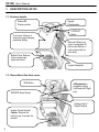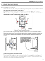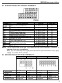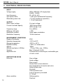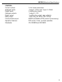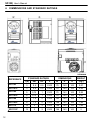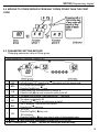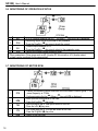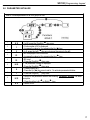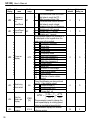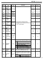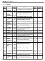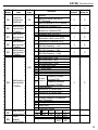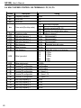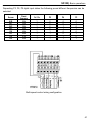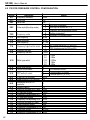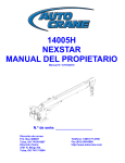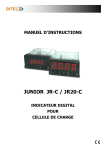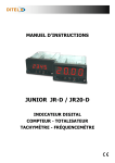
1
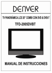
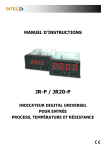
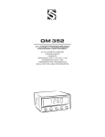
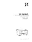
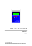
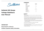
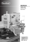
Variable Speed Drive User's Manual VARIABLE SPEED DRIVE User´s Manual SD10MT01BI Rev. B POWER ELECTRONICS ESPAÑA C/ Leonardo da Vinci, 24 - 26 PARQUE TECNOLOGICO 46980 · PATERNA · VALENCIA · ESPAÑA Atención al Cliente. 902 40 20 70 Tel. +34 96 136 65 57 · Fax. +34 96 131 82 01 www.power-electronics.com [email protected] SD100| User’s Manual 2 SD100 IMPORTANT NOTES RECEPTION The SD100 are carefully tested and perfectly packed before leaving the factory. In case of transport damage, notify it to transport agency and to POWER ELECTRONICS Tf. International +34 96 136 65 57, not later than 24hrs from delivery date. UNPACKING Make sure model and serial number of the variable speed drive are the same in the box, delivery note and unit. Each variable speed drive is supplied with el SD100 Technical manual in spanish, german and english. SAFETY It’s electrcian’s responsability to ensure the configuraction and installation of the SD100 SERIES meets the requirements of any site specific, local and national electri cal regulations. The SD100 Series operates from HIGH VOLTAGE, HIGH ENERGY ELECTRICAL SUPPLIES. Always isolate before servicing. Service only by qualified personnel. For any question or enquiry please contact POWER ELECTRONICS Technical Departament or with your local distributor. The SDRIVE100 Series contains static sensitive printed circuit boards. Use statisc safe procedures when handling these boards. 3 SD100| User’s Manual REVISIONS Date May 2003 4 Revision A Description SD100| Index INDEX 1. DESCRIPTION SD100............................................................................................. 1.1. Product details.Appearance. 1.2. View without the front cover. 6 2. MOUNTING AND WIRING........................................................................................ 7 2.1. Installation precautions. 2.2. Wiring terminals. 2.3. Power terminals. 2.4. Specifications for control terminals. 2.5. Specifications for power terminals. 3. ELECTRICAL SPECIFICATIONS.......................................................................... 4. DIMMENSIONS AND STANDARD RATINGS........................................................ 12 5. PROGRAMMING KEYPAD..................................................................................... 13 5.1. Keypad features. 5.2. Parameter groups in SD100. 5.3. Moving between groups. 5.4. Moving to other groups from any codes other than the first code. 5.5. Parameter setting method. 5.6. Monitoring of operation status. 5.7. Monitoring of Motor rpm. 5.8. Parameter initialize. 6. FAULT MESSAGES................................................................................................. 18 6.1. Monitor fault. 6.2. Fault display and information. 7. FUNCTION LIST...................................................................................................... 20 7.1. Drive group. 7.2. Function group 1. 7.3. Function group 2. 7.4. I / O group. 8. BASIC OPERATION............................................................................................... 37 8.1. Frequency Setting via keypad & operating via terminals. 8.2. Frequency Setting via potentiometer & operating via terminals. 8.3. Frequency Setting via potentiometer & operating via the Run key. 8.4. Multi-peed control via terminals P3, P4, P5. 8.5. PID for pressure control configuration. 10 5 SD100| User’s Manual 1. DESCRIPTION SD100 1.1. Product details. Status LED Display window Front cover: Remove it when wiring and changing parameter setting. Bottom Cover: Remove it when wiring input power and motor. Keypad Potentiometer. STOP/RST Button Body slot: When front cover is pulled back till this line and lifted up, it can be remove d from main body. Inverter Nameplate 1.2. View without the front cover. RUN Button NPN/PNP Select Switch 4- Way button for parameter setting (Up/Domn/Left/ Right key). Analogue Input / Output Terminal. Inverter Ground terminal. Caution : Remove the bottom cover to access the terminal. 6 SD100| Mounting and Wiring 2. MOUNTING AND WIRING 2.1 Installation precautions Handle the inverter with care to prevent damage to the plastic components. Do not hold the inverter by the front cover. It may fall off. 2 lInstall the inverter in a place where it is immune to vibration (5.9 m/s or less). lThe inverter is under great influence of ambient temperature. Install in a location where temperature is within the permissible range (-10~50°C). Ambient Temp Checking Location. The inverter will be very hot during operation. Install it on a non-combustible surface. Mount the inverter on a flat, vertical and level surface. Inverter orientation must be vertical (top up) for proper heat dissipation. Also leave sufficient clearances around the inverter. Protect from moisture and direct sunlight. Do not install the inverter in any environment where it is exposed to waterdrops, oil mist, dust, etc. Install the inverter in a clean place or inside a "totally enclosed" panel which does not accept any suspended matter. 7 SD100| User’s Manual 2.2 WIRING TERMINALS 2.3 POWER TERMINALS 8 SD100| Mounting and Wiring 2.4 SPECIFICATIONS FOR CONTROL TERMINALS Terminal Terminal Description Wire size Torque (Nm) P1/P2/P3 2 Multi- function input T/M P1- P5 22 AWG, 0.3 mm 0.4 P4/P5 CM Common Terminal for P1-P5, AM, P24 22 AWG, 0.3 mm2 0.4 2 VR 12V power supply for external potentiometer 22 AWG, 0.3 mm 0.4 2 V1 0-10V Analog Voltage input 22 AWG, 0.3 mm 0.4 2 I 0-20mA Analog Current input 22 AWG, 0.3 mm 0.4 2 AM Multi- function Analog output 22 AWG, 0.3 mm 0.4 2 MO Multi- function open collector output T/M 20 AWG, 0.5 mm 0.4 2 EXTG Ground T/M for MO 20 AWG, 0.5 mm 0.4 P24 24V Power Supply for P1-P5 20 AWG, 0.5 mm2 0.4 2 30A 20 AWG, 0.5 mm 0.4 Fault relay A/B contact output 2 30B 20 AWG, 0.5 mm 0.4 2 30C 30A, B Common 20 AWG, 0.5 mm 0.4 NOTE: Tie the control wires more than 15cm away from the control terminals. Otherwise, it interferes front cover reinstallation. When you use external power supply for multi-function input terminal (P1~P5), apply voltage more than 12V to activate. 2.5 SPECIFICATIONS FOR POWER TERMINALS SD1103 SD1105 L1 N + SD1108 SD1112 +1 L1 N + +1 U Input wire size Out wire Ground Wire Terminal Lug Tightening Torque 2 2mm 2 2mm 2 2mm 2 2mm ,3.5 φ 13kgf /cm V 2 U VW W 2mm 2 2mm 2 2mm 2 2mm ,3.5 φ 13kgf/cm 2 3.5mm 2 3.5mm 2 3.5mm 2 3.5mm ,3.5 φ 15kgf/cm 2 3.5mm 2 3.5mm 2 3.5mm 2 3.5mm ,3.5 φ 15kgf /m 9 SD100| User’s Manual 3. ELECTRICAL SPECIFICATIONS INPUT Voltage supply Input frequency Input power factor Momentary power loss OUTPUT Motor output voltage Current overload capacity Frequency range Efficiency (full load) Modulation method Modulation frequency ENVIRONMENT CONDITIONS Degree of protection Operation temperature Storage temperature Relative humidity Altitude Altitude loss factor (>1000m) Vibration Application site PROTECTIONS SD100 Drive trip Alarm condition 10 200 to 230V/AC ±10 single phase 0,4KW - 2,2KW. 50 - 60 Hz. ±5% > 0,98 (over fundamental frequency) < 15 mS (continuous operation). > 15 mS (autoreset). 0 to input voltage 150% during 60sec. 200% during 1 sec. 0 to ±400Hz > 98% Vector space modulation 15 kHz maximum IP20 -10ºC to 50°C -20ºC to +65°C < 90%, no condensation 1000m -1% per 100m; max. 3000m. Max. 5.9m/sec2 (0.6G) Protected from corrosive gas, combustible gas, oil mist or dust. Over-voltage. Under-voltage. Over-current. Ground fault current detection. Over-temperature of inverter and motor. Output phase open. Overload. Communication error. Loss of frequency command. H / W fault. Stall prevention Overload SD100| Electrical Specifications CONTROL Control method Analogue inputs Digital inputs Analogue outputs Digital output Relay output Communications port Operation features Standards V /Hz, Vector sensorless 1 input 0 - 10Vcc and 1 input 0- 20mA. 5 multifunction inputs 1 output 0 - 10V 1 multifunction output, open collector. 1 fault relay 2A 30Vdc 0.5A 125Vac RS485 and Modbus RTU protocol (as accesory) PID control, 3-wire, up-down operation. CE, ISO9001and ISO14000 11 SD100| User’s Manual 4. DIMMENSIONS AND STANDARD RATINGS REFERENCE 12 STANDARD RATINGS DIMENSIONS WEIGHT I (A) kW HP V W H D (Kg.) SD1103 3 0,4 0,5 230II 79 143 143 0,87 SD1103F 3 0,4 0,5 230II 79 143 143 0,95 SD1105 5 0,75 1 230II 79 143 143 0,89 SD1105F 5 0,75 1 230II 79 143 143 0,97 SD1108 8 1,5 2 230II 156 143 143 1,79 SD1108F 8 1,5 2 230II 156 143 143 1,94 SD1112 12 2 3 230II 156 143 143 1,85 SD1112F 12 2 3 230II 156 143 143 2 SD100| Programming keypad 5. PROGRAMMING KEYPAD 5.1 KEYPAD FEATURES FWD REV 7-Segment (LED Display ) RUN STOP/RST 4-Way button p Up q Down t Left u ˜ Right Prog/Ent Key Poten tiometer Lit during forward run Lit during reverse run Display l l FWD/REV LED 7 Segment LED Buttons l l l l RUN STOP/RST 4-Way Button Potentiometer Display Blinks when a fault occurs Displays operation status and parameter information. Keys Used to give a run command STOP : Stop the operation RST: Reset faults Programming keys: (Up/Down/Left/Right arrow and Prog/Ent keys). Used to scroll through codes or increase parameter value Used to scroll through codes or decrease parameter value Used to jump to other parameter groups or move a cursor to the left to change the parameter. Used to jump to other parameter groups or move a cursor to the righ to change the parameter. Used to set the parameter value or save the changed parameter value. Used to change the value of run frequency. 13 SD100| User’s Manual 5.2 PARAMETER GROUPS IN SD100 There are 4 different parameter groups in SD100 series as shown below. Drive group Function group 1 Function group 2 I / O Group Basic parameters necessary for the inverter to run. Parameters such as Target frequency, Accel/Decel time are settable. Basic function parameters to adjust output frequency and voltage. Advanced function parameters to set parameters for such as PID Operation and second motor operation. Parameters necessary to make up a sequence using Multi-function input/output terminal. 5.3 MOVING BETWEEN GROUPS 14 SD100| Programming keypad 5.4 MOVING TO OTHER GROUPS FROM ANY CODES OTHER THAN THE FIRST CODE 5.5 PARAMETER SETTING METHOD Changing parameter value in Drive group. When changing ACC time from 5.0 sec to 16.0 1 0.0 2 ACC 3 5.0 4 5.0 5 6.0 6 06.0 7 16.0 8 ACC -. In the first code “0.0” , press the Up (p) key once to go to the second code. -. ACC [Accel time] is displayed. -. Press the Prog/Ent key ( ˜) once. -. Preset value is 5.0, and the cursor is in the digit 0. -. Press the Left (t) key once to move the cursor to the left. -. The digit 5 in 5.0 is active. Then press the Up (p) key once. -. The value is increased to 6.0 -. Press the Left (t) key to move the cursor to the left. -. 0.60 is displayed. The first 0 in 0.60 is active. -. Press the Up ( p) key once. -. 16.0 is set. -. Press the Prog/Ent ( ˜) key once. -. 16.0 is blinking. -. Press the Prog/Ent ( ˜) key once again to return to the parameter name. -. ACC is displayed. Accel time is changed from 5.0 to 16.0 sec. In step 7, pressing the Left (t) or Right ( u) key while 16.0 is blinking will disable the setting. 15 SD100| User’s Manual 5.6 MONITORING OF OPERATION STATUS 1 0.0 2 CUr -. In [0.0], continue pressing the Up (p) or Down ( q) key until [Cur] is displayed. -. Monitoring output current is provided in this parameter. -. Press the Prog/Ent ( ˜) key once to check the current. -. Present output current is 5.0 A. 3 5.0 -. Press the Prog/Ent ( ˜) key once to return to the parameter name. 4 CUr -. Return to the output current monitoring code. Other parameters in Drive group such as dCL (Inverter DC link current) or vOL (Inverter output voltage) can be monitored via the same method. 5.7 MONITORING OF MOTOR RPM. 16 1 57.6 2 rPM 3 730 4 173 5 rPM -. Present run frequency can be monitored in the first code of Function group 1. The preset frequency is 57.6Hz. -. Continue pressing the Up (p) /Down ( q) key until rPM is displayed. -. Motor rpm can be monitored in this code. -. Press the Prog/Ent ( ˜) key once. -. Last three digits 730 in 1730 rpm is shown on the LED. -. Press the Left (t) key once. -. First three digits173 in 1730 rpm are shown on the LED. -. Press the Prog/Ent (˜) key once. -. Return to the rPM code. SD100| Programming keypad 5.8 PARAMETER INITIALIZE How to initialize parameters of all four groups in H93 1 H0 2 1 3 3 4 03 5 93 6 H 93 7 0 8 1 9 H 93 10 H0 -. In H0, press the Prog/Ent (˜) key once. -. Code number of H0 is displayed. -. Increase the value to 3 by pressing the Up (p) key. -. In 3, press the Left ( t) key once to move t he cursor to the left. -. 03 is displayed. 0 in 03 is active. -. Increase the value to 9 by pressing the Up (p) key. -. 93 is set. -. Press the Prog/Ent ( ˜ ) key once. -. The parameter number is displayed. -. Press the Prog/Ent ( ˜ ) key once. -. Present setting is 0. -. Press the Up ( p) key once to set to 1 to activate parameter initialize. -. Press the Prog/Ent ( ˜ ) key once. -. Return to the parameter number after blinking. Parameter initialize has been complete. -. Press the either Left (t) or Right (u) key. -. Return to H0. 17 SD100| User’s Manual 6. FAULT MESSAGES 6.1 MONITOR FAULTS 1 OCt 2 30.0 3 5.0 4 ACC 5 nOn -. This message appears when an Overcurrent fault occurs. -. Press the Prog/Ent ( ˜ ) key once. -. The run frequency at the time of fault (30.0) is displayed. -. Press the Up ( p) key once. -. The output current at the time of fault is displayed. -. Press the Up ( p) key once. -. Operating status is displayed. A fault occurred during acceleration. -. Press the STOP/RST key once. -. A fault condition is cleared and “nOn” is displayed. 6.2 FAULT DISPLAY AND INFORMATION Display Oct Oft I OL OL t 18 Fault Over current Ground fault current Inverter Overload Overload trip Description The inverter turns off its output when the output current of the inverter flows more than 200% of the inverter rated current. The inverter turns off its output when a ground fault occurs and the ground fault current is more than the internal setting value of the inverter. The inverter turns off its output when the output current of the inverter flows more than the rated level (150% for 1 minute). The inverter turns off its output if the output current of the inverter flows at 150% of the inverter rated current for more than the current limit time (1 min). SD100| Fault Messages Display Fault OH t Heat sink overheat COL DC link capacitor overload Pot Output Phase loss Out Out EtH EEP HWE Err FAn ESt EtA EtB __L Description The inverter turns off its output if the heat sink overheats due to a damaged cooling fan or an alien substance in the cooling fan by detecting the temperature of the heat sink. The inverter turns off its output when it is time to replace the old DC link capacitor to a new one. The inverter turns off its output when the one or more of the output (U, V, W) phase is open. The inverter detects the output current to check the phase loss of the output. The inverter turns off its output if the DC voltage of the main circuit Over voltage increases higher than 400 V when the motor decelerates. This fault can also occur due to a surge voltage generated at the power supply system. The inverter turns off its output if the DC voltage is below 200V because Low voltage insufficient torque or overheating of the motor can occur when the input voltage of the inverter drops. The internal electronic thermal of the inverter determines the overheating Electronic of the motor. If the motor is overloaded the inverter turns off the output. Thermal The inverter cannot protect the motor when driving a motor having more than 4 poles or multi motors. Parameter save This fault message is displayed when user-setting parameters fails to be error entered into memory. Inverter This fault message is displayed when an error occurs in the control hardware fault circuitry of the inverter. Communication This fault message is displayed when the inverter cannot communicate Error with the keypad. Cooling fan This fault message is displayed when a fault condition occurs in the fault inverter cooling fan. Used for the emergency stop of the inverter. The inverter instantly turns off the output when the EST terminal is turned on. Instant cut off Caution : The inverter starts to regular operation when turning off the BX terminal while FX or RX terminal is ON. External fault A When multi -fun ction input terminal (I20 -I24) is set to 18 {External fault contact input signal input : A (Normal Open Contact)}, the inverter turns off the output. External fault B When multi -function input terminal (I20-I24) is set to 18 {External fault contact input signal input : B (Normal Close Contact)}, the inverter turns off the output. Operating When inverter operation is set via Analog input (0 -10V or 0-20mA input) method when or option (RS485) and no signal is applied, operation is done according the frequency to the method set in I62 (Operating method when the frequency command is reference is lost). lost 19 SD100| User’s Manual 7. FUNCTION LIST 7.1 DRIVE GROUP LED display 0.0 ACC dEC Drv Frq Parameter name Min/Max range Description This parameter sets the frequency that the inverter is commanded to output. During Stop: Frequency Command Frequency 0/400 During Run: Output Frequency command [Hz] During Multi-step operation: Multi -step frequency 0. It cannot be set greater than F21 - [Max frequency]. Accel time 0/6000 During Multi-Accel/Decel operation, this Decel time [s] parameter serves as Accel/Decel time 0. Run/Stop via Run/Stop key on the 0 keypad FX : Motor forward run 1 Run/Stop RX : Motor reverse run Drive mode via control FX : Run/Stop enable (Run/Stop mode) 0/3 2 terminal RX : Motor reverse rotation Operation via Communication 3 Option 0 Digital Setting via Keypad 1 Setting via Keypad 2 1 Setting via potentiometer 2 on the keypad(V0) Setting via V1 terminal 3 Setting via I terminal 4 Frequency mode 0/8 via potentiometer 5 Analog Setting on the keypad + I terminal Setting via V1 + I terminal 6 7 St1 St2 St3 CUr rPM dCL 20 Multi -Step frequency 1 Multi -Step frequency 2 Multi -Step frequency 3 Output current Motor RPM Inverter DC link voltage Factory defaults Adjustable during run 0.0 O 5.0 10.0 O O 1 X 0 X 10.0 O 20.0 O 30.0 O - - - - - - Setting via potentiometer on the keypad + V1 terminal Modbus-RTU Communication This parameter sets Multi- Step frequency 1 during Multi-step operation. 0/400 This parameter sets Multi- Step [Hz] frequency 2 during Multi-step operation. This parameter sets Multi- Step frequency 3 during Multi-step operation. This parameter displays the output current to the motor. This parameter displays the number of Motor RPM. This parameter displays DC link voltage inside the inverter. 8 SD100| Functions List LED display Parameter name vOL User display select nOn Fault Display drC Direction of motor rotation select Min/Max range F/r Description This parameter displays the item selected at H73- [Monitoring item select]. Output voltage vOL Output power POr Torque tOr This parameter displays the types of faults, frequency and operating status at the time of the fault This parameter sets the direction of motor rotation when drv - [Drive mode] is set to either 0 or 1. Forward F Reverse r Factory defaults Adjustable during run vOL - - - F O Factory defaults Adjustable during run 1 O 0 X 0 X 0 X 5.0 X 1.0 X 50 X 7.2 FUNCTION GROUP 1 LED display Parameter name F0 Jump code F1 Forward/ Reverse run disable] F2 F3 Accel pattern Decel pattern F4 Stop mode select F8 DC Brake start frequency F9 DC Brake wait time F10 DC B rake voltage Min/Max range Description This parameter sets the parameter code number to jump. 0 Fwd and rev run enable 0/2 1 Forward ru n disable 2 Reverse run disable 0 Linear. 0/1 1 S-curve 0 Decelerate to stop 0/2 1 Stop via DC brake 2 Free run to stop This parameter sets DC brake start frequency. 0/60 [Hz] It cannot be set below F23 [Start frequency]. When DC brake frequency is reached, the inverter holds the 0/60 [s] output for the setting time before starting DC brake. This parameter sets the amount 0/200 of DC voltage applied to a motor. [%] It is set in percent of H33 – [Motor rated current]. 0/60 21 SD100| User’s Manual LED display Min/Max range F11 DC Brake time 0/60 [s] F12 DC Brake start voltage 0/200 [%] F13 DC Brake start time 0/60 [s] F14 Time for magnetizing a motor 0/60 [s] F20 Jog frequency 0/400 [Hz] F21 Max frequency 40/400 * [Hz] F22 Base frequency 30/400 [Hz] F23 F24 22 Parameter name Start frequency Frequency high/low limit select 0/10 [Hz] 0/1 Description This parameter sets the time taken to apply DC current to a motor while motor is at a stop. This parameter sets the amount of DC voltage before a motor starts to run. It is set in percent of H33 – [Motor rated current]. DC voltage is applied to the motor for DC Brake start time before motor accelerates. This parameter applies the current to a motor for the set time before motor accelerates during Sensorless vector control. This parameter sets the frequency for Jog operation. It cannot be set above F21 – [Max frequency]. This parameter sets the highest frequency the inverter can output. It is frequency reference for Accel/Decel (See H70) If H40 is set to 3(Sensorless vector), it can be s ettable up to 300Hz *. Caution : Any frequency cannot be set above Max frequency. The inverter outputs its rated voltage to the motor at this frequency (see motor nameplate). In case of using a 50Hz motor, set this to 50Hz. The inverter starts to output its voltage at this frequency. It is the frequency low limit. This parameter sets high and low limit of run frequency. Factory defaults Adjustable during run 1.0 X 50 X 0 X 1.0 X 10.0 O 60.0 X 60.0 X 0.5 X 0 X SD100| Functions List LED Parameter name display F25 F26 F27 F28 F29 F30 F31 F32 F33 F34 F35 F36 F37 F38 Min/Max range Description This parameter sets high limit of the run Frequency 0/400 frequency. high limit [Hz] It cannot be set above F21 – [Max frequency]. This parameter sets low limit of the run Frequency low 0/400 frequency. It cannot be set above F25 - [Frequency limit [Hz] high limit] and below F23 – [Start frequency]. Torque Boost 0 Manual torque boost 0/1 select 1 Auto torque boost This parameter sets the amount of Torque boost torque boost applied to a motor during in forward 0/15 [%] forward run. direction It is set in percent of Max output voltage. This parameter sets the amount of Torque boost torque boost applied to a motor during in reverse 0/15 [%] reverse run. direction It is set as a percent of Max output voltage 0 Linear V/F pattern 0/2 1 Square 2 User V/F User V/F 0/400 [Hz] frequency 1 User V/F 0/100 [%] voltage 1 This parameter is active when F30 – User V/F 0/400 [Hz] [V/F pattern] is set to 2 {User V/F}. frequency 2 It cannot be set above F21 – [Max User V/F 0/100 [%] frequency]. voltage 2 The value of voltage is set in percent of User V/F 0/400 [Hz] H70 – [Motor rated voltage]. frequency 3 The values of the lower-numbered User V/F 0/100 [%] parameters cannot be set above those of voltage 3 higher-numbered. User V/F 0/400 [Hz] frequency 4 User V/F voltage 4 0/100 [%] Factory defaults Adjustable during run 60.0 X 0.5 X 0 X 5 X 5 X 0 X 15.0 X 25 X 30.0 X 50 X 45.0 X 75 X 60.0 X 100 X 23 SD100| User’s Manual LED Parameter name display F39 F40 F50 F51 F52 F53 24 Min/Max range Description This parameter adjusts the amount of Output voltage 40/110 output voltage. adjustment [%] The set value is the percentage of input voltage Energy-saving 0/30 [%] This parameter decreases output level voltage according to load status. Electronic This parameter is activated when the thermal 0/1 motor is overheated (time-inverse). select This parameter sets max current capable of flowing to the motor continuously for 1 Electronic minute. thermal level The set value is the percentage of H33 – [Motor rated current]. for 1 minute 50/200 It cannot be set below F52 –[Electronic [%] thermal level for continuous]. This parameter sets the amount of Electronic current to keep the motor running thermal level continuously. for continuous It cannot be set higher than F51 – [Electronic thermal level for 1 minute]. Standard motor having cooling fan 0 directly connected to the shaft Motor cooling 0/1 method A motor using a separate motor to 1 power a cooling fan. F54 Overload warning level F55 Overload warning time F56 Overload trip select F57 Overload trip level F58 Overload trip time 30/150 [%] This parameter sets the amount of current to issue an alarm signal at a relay or multi function output terminal (see I54, I55). The set value is the percentage of H33 [Motor rated current]. This parameter issues an alarm signal when the current greater than F540/30 [s] [Overload warning level] flows to the motor for F55- [Overload warning time]. This parameter turns off the inverter 0/1 output when motor is overloaded. This parameter sets the amount of 30/200 overload current. [%] The value is the percentage of H33[Motor rat ed current]. This parameter turns off the inverter output when the F57- [Overload trip 0/60 [s] level] of current flows to the motor for F58- [Overload trip time]. Factory defaults Adjustable during run 100 X 0 0 0 0 150 0 100 0 0 0 150 0 10 0 1 0 180 0 60 0 SD100| Functions List LED Parameter name display F59 Stall prevention select F60 Stall prevention level Min/Max range Description This parameter stops accelerating during acceleration, decelerating during constant speed run and stops decelerating during deceler ation. 0/7 During During During Deceleration constant Acceleration speed Bit 2 Bit 1 Bit 0 0 P 1 P 2 P P 3 P 4 P P 5 P P 6 P P P 7 This para meter sets the amount of current to activate stall prevention 30/150 function during Accel, constant or Decel [%] run. The set value is the percentage of the H33- [Motor rated current]. Factory defaults Adjustable during run 0 X 150 X Factory defaults Adjustable during run 7.3 FUNCTION GROUP 2 LED display Parameter name Min/Max range H0 Jump code H1 H2 H3 H4 Fault history 1 Fault history 2 Fault history 3 Fault history 4 H6 Reset fault history 0/1 H7 Dwell frequency F23/400 [Hz] H5 Fault history 5 1/95 - Description This parameter sets the code number jump. This parameter stores information on the types of faults, the frequency, the current and the Accel/Decel condition at the time of fault. The last fault is automatically stored in the H 1 - [Fault history 1]. This parameter clears the fault history saved in H 1-5. When run frequency is issued, motor starts to accelerate after dwell frequency is applied to the motor during H8 - [Dwell time]. [Dw ell frequency] can be set within the range of F21- [Max frequency] and F23[Start frequency]. 1 O nOn nOn nOn nOn - 0 O 5.0 X nOn - 25 SD100| User’s Manual LED display H8 Dwell time H10 Skip frequency select H11 H12 H13 H14 H15 H16 26 Parameter name Skip frequency low limit 1 Skip frequency high limit 1 Skip frequency low limit 2 Skip frequency high limit 2 Skip frequency low limit 3 Skip frequency high limit 3 H17 S- Curve accel/decel start side H18 S- Curve accel/decel end side H19 Output phase loss protection select H20 Power On Start select H21 Restart after fault reset Min/Max range Description This parameter sets the time for dwell 0/10 [s] operation. This parameter sets the frequency range to skip to prevent undesirable 0/1 resonance and vibration on the structure of the machine. Run frequency cannot be set within the range of H11 thru H16. 0/400 [Hz] The frequency values of the low numbered parameters cannot be set above those of the high numbered ones. Set the speed reference value to form 1/100 [%] a curve at the start during accel/decel. If it is set higher, linear zone gets smaller. Set the speed reference value to form a c urve at the end during accel/decel. 1/100 [%] If it is set higher, linear zone gets smaller. Inverter turns off the output when the 0/1 phase of the inverter output (U, V, W) is not properly connected. This parameter is activated when drv is set to 1 or 2 (Run/Stop via Control terminal). 0/1 Motor starts acceleration after AC power is applied while FX or RX terminal is ON. This parameter is active when drv is set to 1 or 2 (Run/Stop via Control terminal). Motor accelerates after the fault condition is reset while the FX or RX terminal is ON. Factory defaults Adjustable during run 0.0 X 0 X 10.0 X 15.0 X 20.0 X 25.0 X 30.0 X 35.0 X 40 X 40 X 0 O 0 O SD100| Functions List LED display H22 H23 H24 H25 H26 Parameter name Speed Search Select Current level during Speed search P gain during Speed search I gain during speed search Number of Auto Restart try Min/Max range 0/15 80/200 [%] Description This parameter is active to prevent any possible fault when the inverter outputs its voltage to the running motor. 2.Restar 3.Opera- 4.Normal 1. H20- t after after acceleraPower instant tion fault tion On start power occurred failure Bit 3 Bit 2 Bit 1 Bit 0 0 P 1 P 2 P P 3 P 4 P P 5 P P 6 P P P 7 P 8 P P 9 P P 10 P P P 11 P P 12 P P P 13 P P P 14 P P P P 15 This parameter limits the amount of current during speed search. The set value is the percentage of the H33[Motor rated current]. Factory defaults Adjustable during run 0 O 100 O 0/9999 It is the Proportional gain used for Speed Search PI controller. 100 O 0/9999 It is the Integral gain used for Speed search PI controller. 1000 O 0/10 This parameter sets the number of restart tries after a fault occurs. Auto Restart is deactivated if the fault outnumbers the restart tries. This function is active when [drv] is set to 1 or 2 {Run/Stop via control terminal}. Deactivated during active protection function (OHT, LVT, EXT, HWT etc.) 0 O 27 SD100| User’s Manual LED display Parameter name Min/Max range H27 Auto Restart time 0/60 [s] H30 Motor type 0.2/2.2 select H31 Number of 2/12 motor poles H32 Rated slip frequency 0/10 [Hz] Description · This parameter sets the time between restart tries. 0.2 0.2 kW 0.4 0.4 kW 0.75 0.75 kW 1.5 1.5 kW 2.2 2.2 kW This setting is displayed via rPM in drive group. 28 Motor rated 1.0/20 current [A] H34 No Load Motor Current 0.1/12 [A] H36 Motor efficiency 50/100 [%] H37 Load inertia rate 0/2 Adjustable during run 1.0 O 0.4 X 4 X 3.0 X 1.8 X 0.9 X 72 X 0 X rpm× P f s = fr − 120 fs fr rpm H33 Factory defaults = Rated slip frequency = Rated frequency = Motor nameplate RPM P = Number of Motor poles Enter motor rated current on the nameplate. Enter the current value detected when the motor is rotating in rated rpm after the load connected to the motor shaft is removed. Enter the 50% of the rated current value when it is difficult to measure H34 - [No Load Motor Current]. Enter the motor efficiency (see motor nameplate). Select one of the following according to motor inertia. Less than 10 times that of motor 0 inertia 1 About 10 times that of motor inertia More than 10 times that of motor 2 inertia SD100| Functions List LED display Parameter name Min/Max range H39 Carrier frequency select H40 Control mode select 0/3 H41 Auto tuning 0/1 H42 H44 H45 H46 H50 H51 H52 H53 H54 [Stator resistance (Rs)] [Leakage inductance σ (L )] Sensorless P gain Sensorless I gain PID Feedback select [P gain for PID controller] [Integral time for PID controller (I gain)] Differential time for PID controller (D gain) F gain for PID controller 1/15 [kHz] Description · This parameter affects the audible sound of the motor, noise emission from the inverter, inverter temp, and leakage current. If the value is set higher, the inverter sound is quieter but the noise from the inverter and leakage current will become greater. 0 {Volts/frequency Control} 1 {Slip compensation control} 2 {PID Feedback control} 3 {Sensorless vector control} If this parameter is set to 1, it automatically measures parameters of the H42 and H43. Factory defaults Adjustable during run 3 O 0 X 0 X 0/5.0[Ω ] This is the value of the motor stator resistance. - X 0/300.0 [mH] This is leakage inductance of the stator and rotor of the motor. - X P gain for Sensorless control 1000 O I gain for Sensorless control 100 O 0 X 300.0 O 1.0 O 0.0 O 0.0 O 0/32767 0/1 0 Terminal I input (0 ~ 20 mA) 1 Terminal V1 input (0 ~ 10 V) 0/999.9 [%] 0.1/32.0 [sec] This parameter sets the gains for the PID controller. 0.0/30.0 [sec] 0/999.9 [%] This is the Feed forward gain for the PID controller. 29 SD100| User’s Manual 30 LED display Parameter name Min/Max range H70 Frequency Reference for Accel/Decel 0/1 H71 Accel/Decel time scale 0/2 H72 Power on display 0/13 H73 Monitoring item select 0/2 H74 Gain for Motor rpm display 1/1000 [%] H79 Software version 0/10.0 Description The Accel/Decel time is the time 0 that takes to reach the F21 – [Max frequency] from 0 Hz. The Accel/Decel time is the time 1 that takes to reach a target frequency from the run frequency. 0 Settable unit: 0.01 second. 1 Settable unit: 0.1 second. 2 Settable unit: 1 second. This parameter selects the parameter to be displayed on the keypad when the input power is first applied. 0 Frequency command 1 Accel time 2 Decel time 3 Drive mode 4 Frequency mode 5 Multi -Step frequency 1 6 Multi -Step frequency 2 7 Multi -Step frequency 3 8 Output current 9 Motor rpm 10 Inverter DC link voltage 11 User display select 12 Fault display Direction of motor rotation 13 select One of the following can be monitored via vOL - [User display select]. 0 Output voltage [V] 1 Output power [kW] 2 Torque [kgf ⋅ m] 120 × f H 74 = × H 31 100 This parameter is used to change the motor speed display to rotating speed (r/min) or mechanical speed (m/mi). This parameter displays the inverter software version. Factory defaults Adjustable during run 0 X 1 O 0 O 0 O 1.0 X RPM SD100| Functions List LED display H81 H82 H83 H84 H85 H86 H87 H88 H89 H90 Parameter name Software version nd 2 motor Accel time nd 2 motor Decel time 2 nd motor base frequency nd Min/Max range Description 0/6000 [s] Factory defaults Adjustable during run 5.0 O 10.0 O 30/400 [Hz] 60.0 X 0/2 0 X 5 X 5 X 150 X 150 O 100 O 1.8 X 0 X 2 motor V/F pattern nd 0/15 [%] 2 motor forward torque boost nd This parameter is active when the 2 motor 30/150 selectedndterminal is ON after I20- I24 is set reverse to 12 {2 motor select}. [%] torque boost nd 2 motor stall prevention level 50/200 2 nd motor [%] Electronic thermal level for 1 min nd 2 motor Electronic 0.1/20 thermal level [A] for continuous This parameter is used to initialize parameters back to the factory default values. 0 All parameter groups are initialized to factory default value. Only Drive group is initialized. Only Function group 1 is initialized . Only Function group 2 is initialized. H93 Parameter initialize 0/5 H94 Passwor d register 0/FFF Password for H95-[Parameter lock]. 0 O Parameter lock 0/FFF This parameter is able to lock or unlock parameters by typing password registered in H94. UL(Unlock) Parameter change enable L (Lock) Parameter change disable 0 O H95 1 2 3 4 31 SD100| User’s Manual 7.4 I / O GROUP LED Parameter name display I0 I1 I2 Filter time constant for V0 input V0 input Min voltage I3 Frequency corresponding to I 2 I4 V0 input Max voltage I5 I6 I7 Frequency corresponding to I 4 Filter time constant for V1 input V1 input Min voltage I8 Frequency corresponding to I 7 I9 V1 input max voltage I10 I11 I12 I13 I14 I15 32 Jump code Frequency corresponding to I 9 Filter time constant for I input I input minimum current Frequency corresponding to I 12 I input max current Frequency corresponding to I 14 Min/Max range Description Factory defaults Adjustable during run 1 O 0/63 This parameter sets the code number to jump 0/9999 This is used to adjust the analog voltage input signal via keypad potentiometer. 10 O 0/10 [V] Set the minimum voltage of the V0 input. 0 O Set the inverter output minimum frequency at minimum voltage of the V0 input. 0.0 O Set the maximum voltage of the V0 input. 10 O 0/400 [Hz] Set the inverter output maximum frequency at maximum voltage of the V0 input. 60.0 O 0/9999 Set the input section ’s internal filter constant for V1 input. 10 O Set the minimum voltage of the V1 input. 0 O Set the inverter output minimum frequency at minimum voltage of the V1 input. 0.0 O 0/400 [Hz] 0/10 [V] 0/10 [V] 0/400 [Hz] 0/10 [V] Set the maximum voltage of the V1 input. 10 O 0/400 [Hz] Set the inverter output maximum frequency at maximum voltage of the V1 input. 60.0 O 0/9999 Set the input section’s internal filter constant for I input. 10 O 0/20 [mA] Set the Minimum Current of I input. 4 O 0/400 [Hz] Set the inverter output minimum frequency at minimum current of I input. 0.0 O Set the Maximum Current of I input. 20 O 60.0 O 0/20 [mA] 0/400 [Hz] Set the inverter output maximum frequency at maximum current of I input. SD100| Functions List LED display I16 I20 I21 I22 I23 Parameter name Criteria for Analog Input Signal loss Min/Max range 0/2 0/24 I24 1 2 0 Multi- function input terminal P1 define Multi -function input terminal P2 define Multi -function input terminal P3 define Multi -function input terminal P4 define Multi -function input terminal P5 define Description 0 I26 Input terminal status display Output terminal status display Below the value set in I 2/7/12 entered Forward run command {FX} 1 Reverse run command {RX} 2 Emergency Stop Trip {EST} 3 Reset when a fault occurs {RST}. 4 Jog operation command {JOG} 5 Multi -Step frequency – Low 6 Multi -Step frequency – Mid 7 Multi -Step frequency – High 8 9 10 11 12 13 14 Multi Accel/Decel – Low Multi Accel/Decel – Mid Multi Accel/Decel – High DC brake during stop nd 2 motor select Frequency increase Up -down command (UP) operation Frequency decre ase command (DOWN) 3-wire operation External trip: A Contact (EtA) External trip: B Contact (EtB) Exchange between PID operation and V/F operation 15 16 17 18 19 20 21 I25 Disabled Less than half the value set in I 2/7/12 entered 22 Exchange between option and Inverter 23 Analog Hold 24 Accel/Decel Disable BIT4 BIT3 BIT2 BIT1 BIT0 P5 P4 P3 P2 P1 BIT1 BIT0 30AC Factory defaults Adjustable during run 0 O 0 O 1 O 2 O 3 O 4 O - - MO 33 SD100| User’s Manual LED display I27 I30 I31 I32 I33 I34 I35 I36 I37 I38 I39 I40 I41 I42 I43 I44 I45 I46 I47 34 Parameter name Filtering time constant for Multi -function Input terminal Multi-Step frequency 4 Multi -Step frequency 5 Multi -Step frequency 6 Multi -Step frequency 7 Multi -Accel time 1 Multi -Decel time 1 Multi -Accel time 2 Multi -Decel time 2 Multi -Accel time 3 Multi -Decel time 3 Multi -Accel time 4 Multi -Decel time 4 Multi -Accel time 5 Multi -Decel time 5 Multi -Accel time 6 Multi -Decel time 6 Multi -Accel time 7 Multi -Decel time 7 Min/Max range Description Factory defaults Adjustable during run 2/50 If the value is set higher, the response of the Input terminal is getting slower. 15 O 30.0 O 25.0 O 20.0 O 15.0 O 0/400 [Hz] It cannot be set greater than F21 – [Max frequency]. 3.0 3.0 4.0 4.0 0/6000 [s] 5.0 5.0 6.0 6.0 7.0 7.0 8.0 8.0 9.0 9.0 O SD100| Functions List LED display Parameter name Min/Max range I50 Analog output item select 0/3 I51 Analog output level adjustment 10/200 [%] I52 Frequency detection level I53 Frequency detection bandwidth I54 Multi -function output terminal select I55 Multi -function relay select I56 Fault relay output 0/400 [Hz] 0/17 Description 0 1 2 3 Max frequency 150 % 282 V DC 400V 10[V] Output Max. frequen z 150 % 282 V 400V/DC · This parameter is used when I54 – [Multi-function output terminal select] or I55 – [Multi- function relay select] are set to 0-4. · It cannot be set greater than F21 – [Max frequency]. 0 FDT-1 1 FDT-2 2 3 4 5 6 7 8 9 10 11 12 13 14 15 16 17 0/7 0 1 2 FDT-3 FDT-4 FDT-5 Overload {OL} Inverter Overload {IOL} Motor stall {STALL} Over voltage trip {OV} Low voltage trip {LV} Inverter cooling fan overheat {OH} Command loss During run During stop During constant run During speed searching Wait time for run signal input Fault relay output When When the When the setting the trip other low voltage H26– trip occurs [Number of than low auto restart voltage trip occurs try ] Bit 2 Bit 1 Bit 0 P P - Factory defaults Adjustable during run 0 O 100 O 30.0 O 10.0 O 12 17 35 SD100| User’s Manual LED display I56 I60 36 Parameter name Fault relay output Inverter station number Min/Max range 0/7 1/32 I61 Baud rate 0/4 I62 Drive mode select after loss of frequency command 0/2 I63 Wait time after loss of frequency command 0.1/12 [sec] Description 3 4 5 6 7 - P P P P P P - - P P P - Factory defaults Adjustable during run 2 O 1 O 3 O 0 O 1.0 - P This parameter is set when the inverter uses RS485 communication option. Select the Baud rate of the RS485 0 1200 bps 1 2400 bps 2 4800 bps 3 9600 bps 4 19200 bps It is used when frequency command is given via V1 and I terminal or communication option. 0 Continuous operation 1 Free Run stop (Coast to stop) 2 Decel to stop This is the time inverter determines whether there is the input frequency command or not. If there is no frequency command input during this time, inverter starts operation via the mode selected at I62. SD100| Basic operations 8. BASIC OPERATION Caution : The following instructions are given based on the fact that all parameters are set to factory defaults. Results could be different if parameter values are changed. In this case, initialize parameter values (see page 10-17) back to factory defaults and follow the instructions below. 8.1 FREQUENCY SETTING VIA KEYPAD & OPERATING VIA TERMINALS. 1 2 0.0 0.0 3 00.0 4 10.0 5 10.0 6 :10.0 7 :10.0 8 0.0 -. Apply AC input power to the inverter. -. When 0.0 appears, press the Prog/Ent (˜) key once. -. The second digit in 0.0 is lit as shown left. -. Press the Left (t) key twice. -. 00.0 is displayed and the first 0 is lit. -. Press the Up ( p) key. -. 10.0 is set. Press the Prog/Ent (˜) key once. -. 10.0 is blinking. Press the Prog/Ent ( ˜) key once. -. Run frequency is set to 10.0 Hz when the blinking stops. -. Turn on the switch between P1 (FX) and CM termin als. -. FWD (Forward run) lamp begins to blink and accelerating frequency is displayed on the LED. -. When target run frequency 10Hz is reached, 10.0 is displayed. -. Turn off the switch between P1 (FX) and CM terminals. - . FWD lamp begins to blink and decelerating frequency is displayed on the LED. - . When run frequency is reached to 0Hz, FWD lamp is turned off and 10.0 is displayed. Wiring Operating pattern 37 SD100| User’s Manual 8.2 FREQUENCY SETTING VIA POTENTIOMETER & OPERATING VIA TERMINALS . 1 2 0.0 3 Frq 4 0 5 2 6 Frq 7 : 10.0 8 : 10.0 -. Apply AC input power to the inverter. -. When 0.0 appears Press the Up (p) key four times. -. Frq is displayed. Frequency setting mode is selectable. -. Press the Prog/Ent ( ˜) key once. -. Present setting method is set to 0 (freq uency setting via keypad). -. Press the Up ( p) key twice. -. After 2 (Frequency setting via potentiometer) is set, press the Prog/Ent ( ˜) key once. -. Frq is redisplayed after 2 stops blinking. -. Turn the potentiometer to set to 10.0 Hz in either Max or Min direction. -. Turn on the switch between P1 (FX) and CM (See Wiring below). -. FWD lamp begins to blink and the accelerating frequency is displayed on the LED. -. When run frequency 10Hz is reached, the value is displayed as sh own left. -. Turn off the switch between P1 (FX) and CM terminals. -. FWD lamp begins to blink and the decelerating frequency is displayed on the LED. -. When the run frequency is reached to 0 Hz, FWD lamp is turned off and 10.0 is displayed as shown left. Wiring 38 Operating pattern SD100| Basic operations 8.3 FREQUENCY SETTING VIA POTENTIOMETER & OPERATING VIA THE RUN KEY. 1 2 0.0 3 Drv 4 1 5 0 6 Drv 7 Frq 8 0 9 2 10 Frq 11 :10.0 12 :10.0 -. Apply AC input power to the inverter. -. When 0.0 is displayed, press the Up (p) key three times. -. drv is displayed. Operating method is selectable. -. Press the Prog/Ent ( ˜ ) key. -. Check the present operating method (“1” is run via control terminal) -. Press the Prog/Ent ( ˜ ) key and then Down (q) key once. -. After setting “0”, press the Prog/Ent (˜) key. -. “drv” is displayed after “0” is blinking. Operation method is set via the Run key on the keypad. -. Press the Up ( p) key once. -. Different frequency setting method is selectable in this code. -. Press the Prog/Ent ( ˜ ) key. -. Check the present frequency setting method ( “0” is run via keypad). -. Press the Up ( p) key twice. -. After checking “2” (frequency setting via potentiometer), press the Prog/Ent ( ˜ ) key. -. “Frq” is displayed after “ 2” is blinking. Frequency setting is set via the potentiometer on the keypad. -. Turn the potentiometer to set to 10.0 Hz in either Max or Min direction. -. Press the Run key on the keypad. -. FWD lamp begins to blink and accelerating frequency is displayed on the LED. -. When run frequency 10Hz is reached, 10.0 is displayed as shown left. -. Press the STOP/RST key. -. FWD lamp begins to blink and decelerating frequency is displayed on the LED. -. When run frequency is reached to 0Hz, FWD lamp is turned off and 10.0 is displayed as shown left. 220VAC L1(R) N(S) + +1 G U V W 10 Hz Motor RUN ST OP/RST Freq. Run Key MIN MAX Wiring STOP/RST key Operating pattern 39 SD100| User’s Manual 8.4 MULTI-SPEED CONTROL VIA TERMINALS P3, P4, P5. Screen 00.0 acc dec drv Drive mode (Run/stop mode) Frq ST 1 ST 2 ST 3 F 21 F 22 F 23 Frequency mode Multi -step frequency 1 Multi -step frequency 2 Multi -step frequency 3 Max frequency Base frequency Start frequency H 30 Motor type select H 33 I 20 I 21 I 22 I 23 I 24 I 30 I 31 Motor rated current Terminal P1 configuration Terminal P2 configuration Terminal P3 configuration Terminal P4 configuration Terminal P5 configuration Multi -Step frequency 4 Multi -Step frequency 5 I 32 I 33 40 Description Frequency command Accel time Decel time Multi -Step frequency 6 Multi -Step frequency 7 Setting 50Hz 10s 10s 0 Run/Stop via equipad. 1 Run stop via terminal RX , FX. 2 Operation via communication option. 0 Setting via keypad 1 30 Hz (Multivelocidad 1) 35 Hz (Multivelocidad 2) 40 Hz (Multivelocidad 3) 50 Hz Velocidad límite del equipo. 50 Hz 0,1 Hz Velocidad mínima en el arranque 0.4 0.37Kw 0.8 0.75Kw 1.5 1.50Kw 2.2 2.2Kw 3.7 3.7Kw 1.0/20A Configurables Configurables 5 – Speed – L 6 – Speed – M 7 – Spped – H 42 Hz 43 Hz 44 Hz 45 Hz SD100| Basic operations Depending P3, P4, P5 digital input status the following preset different frequencies can be selected: Screen 0.00 St 1 St 2 St 3 I 30 I 31 I 32 I 33 Preset frequency 50Hz 30Hz 35Hz 40Hz 45Hz 50Hz 47Hz 42Hz Fx / Rx P5 P4 P3 1 1 1 1 1 1 1 1 0 0 0 0 1 1 1 1 0 0 1 1 0 0 1 1 0 1 0 1 0 1 0 1 Multi-speed control wiring configuration. 41 SD100| User’s Manual 8.5 PID FOR PRESSURE CONTROL CONFIGURATION. Screen 00.0 ACC DEC DRV Drive mode (Run/stop mode) FRQ Frequency mode F 21 F 22 F 23 Max frequency Base frequency Start frequency F 24 Frequency high/low limit select F 25 F 26 Frquency high limit Frequency low limit H 30 Motor type select H 33 H 40 Motor rated current Control mode select H 50 PID feedback select H 51 H 52 P gain for PID controller Integral time for PID controller Differential time for PID controller Software version Filter time constant for V1 input V1 input Min voltage Frequency corresponding to I7 V1 input Max voltage Frequency corresponding to I9 Filter time constant for I input I input minimum current Frequency corresponding to I12 I input max current Frequency corresponding to I14 H 53 H 79 I6 I7 I8 I9 I 10 I 11 I 12 I 13 I 14 I 15 42 Description Frequency command Accel time Decel time 50Hz 10s 10s 0 1 2 0 8 50 Hz 50 Hz 0,1 Hz 0 1 0Hz 50Hz 0.2 0.4 0.75 1.5 2.2 A 2 0 1 300.0 1.0 0 1.3 10ms 0.00V 0Hz 10.0V 50Hz 10ms 0mA 0Hz 20.0mA 50Hz Setting Run/Stop via equipad. Run stop via terminal RX , FX. Operation via communication option. Setting via keypad 1 Modbus-RTU communication NO (Limits are set by F21 and F23) YES (Limits are set by F25 and 26) 0.2Kw 0.4Kw 0.75Kw 1.5Kw 2.2Kw PID feedback control Terminal input I (0-20mA) Terminal input V1 (0 - 10V) SD100| Basic operations NOTE: Maximum and minimumfrequency limits are set in screen F21(max frequency) and F23 ( Start frequency). NOTE: SD100 do not have 12-30Vdc power supply. External power supply must be requi red. + - P4 P5 VR V1 CM I AM Extern al su pply MO EXTG P24 P1 P2 CM P3 START / STOP 1 2 DT 0082A PID for pressure control wiring configuration. 43 SD100| User’s Manual 44 www.power-electronics.com