1
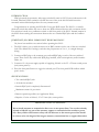
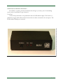
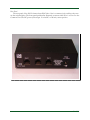
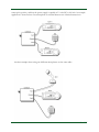
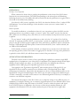
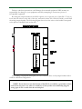
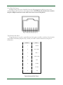
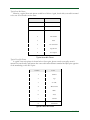
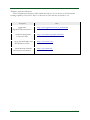
SLS-2 OPERATIONS MANUAL
MANUAL REV. A
LDG SLS-2 Two-Port
RJ45 Switch
LDG Electronics
1445 Parran Road
St. Leonard MD 20685-2903 USA
Phone: 410-586-2177
Fax: 410-586-8475
[email protected] www.ldgelectronics.com
PAGE 1
Table Of Contents
Introduction
3
Jumpstart, or “Real hams don’t read manuals!”
3
Specifications
3
Important Safety Warning
3
Getting to know your SLS-2
4
Front Panel
4
Rear Panel
5
Inside
6
Installation
6
Operation
8
Desktop / Local Operation
8
Remote Operation
8
Application Information
8
SLS-2 RJ45 Pin Diagram
10
Typical Kenwood Mic Pinout
10
Typical Icom Mic Pinout
11
Typical Yaesu Mic Pinout
11
Additional Application Information
12
Technical Support
13
Two-Year Transferrable Warranty
13
Out Of Warranty Service
13
Returning Your Product For Service
13
Product Feedback
14
PAGE 2
INTRODUCTION
LDG pioneered the automatic, wide-range switched-L tuner in 1995. From its laboratories in St.
Leonard, Maryland, LDG continues to define the state of the art in this field with innovative
automatic tuners and related products for every amateur need.
Congratulations on selecting the LDG SLS-2 two-port RJ45 switch. The SLS-2 is a versatile
electronic switch that enables the user to share two RJ45-connected devices with a common device.
Port selection is made via a pushbutton switch on the front panel of the SLS-2. Internal jumpers in
the SLS-2 allow rewiring the connections between the two switched RJ45 jacks and the common
jack.
JUMPSTART, OR “REAL HAMS DON’T READ MANUALS!”
Ok, but at least read this one section before operating the SLS-2:
1. The SLS-2 allows you to switch 8 circuits of an RJ45 common jack to one of the two switched
jacks. The default SLS-2 wiring is such that the port pinouts are 1-to-1, i.e. straight-through
wiring.
2. Connect an RJ45 plug to the common port, and and RJ45 plug to each of the two switched
ports. These can be any cables with RJ45 plugs installed, such as microphones, audio interface
cables, etc.
3. Connect a 12 volt power supply capable of supplying 100 mA to the 2.5 x 5.5 mm coaxial power
jack (center positive).
4. Press the front panel button to toggle the selected port. The front panel LEDs indicate which
port is active.
SPECIFICATIONS
• Two switched RJ45 jacks
• All 8 circuits switched
• Inactive RJ45 jack is completely disconnected
• Maximum current 1A per circuit
• Remote operation possible (see Application Hints)
• Requires 12 volts at 100 mA, 2.5 x 5.5 mm jack, center positive
IMPORTANT SAFETY WARNING
Never install antennas or transmission lines over or near power lines. You can be seriously
injured or killed if any part of the antenna, support or transmission line touches a power
line. Always follow this antenna safety rule: the distance to the nearest power line should
be at least twice the length of the longest antenna, transmission line or support dimension.
PAGE 3
GETTING TO KNOW YOUR SLS-2
Your SLS-2 is a quality, precision instrument that will give you many years of outstanding
service; take a few minutes to get to know it.
Front Panel
On the front panel there is one pushbutton and two LED indicator lights. The button is a
pushbutton toggle switch which selects between the two cables connected to the rear ports. The
LEDs indicate which port is selected.
PAGE 4
Rear Panel
The rear panel of the SLS-2 features three RJ45 jacks. One is a common jack, and the other two
are the switched jacks. The front panel pushbutton alternately connects either Port 1 or Port 2 to the
Common Port. The DC power jack accepts 12 volts DC at 100 mA, center positive.
PAGE 5
Inside
Inside the SLS-2 are two headers with wire jumpers, which allow you to rewire the two switched
ports if desired. The factory wiring is “straight-through”, or 1-to-1 wiring, so that pin 1 of each
switched port connects to pin 1 of the common port, pin 2 to pin 2, and so forth.
The wire jumpers are color coded for convenience; however, the color scheme does not convey
any fixed meaning. If wiring other than straight-through is desired, you will need to desolder the
wire jumpers and re-solder to meet your specific needs. This feature of the SLS-2 allows you to
adapt two similar devices with different pinouts to connect to the same equipment. Be sure to check
the manufacturer’s data sheets of both devices to be certain that the signal levels are compatible, if
you choose to use this feature of the SLS-2.
If you open the case of the SLS-2 in order to rewire the jumper headers, take care not to splash
solder on any exposed traces, potentially causing a short circuit. Also take care to ensure no foreign
objects are left inside the case when re-assembling the lid to the case.
INSTALLATION
Installation of the SLS-2 is fairly straightforward in most cases. Plug one end of an RJ45 cable
into the common port and connect the other end to the piece of equipment you are sharing. Next,
plug an RJ45 cable into each of the switched ports and connect them to each of the two devices
you’d like to switch between. Connect a DC power plug to the DC power jack, making sure the
PAGE 6
center pin is positive, and that the power supply is capable of 12 volts DC at 100 mA. An example
application is shown below. One microphone is switched between two identical transceivers.
Another example shows using two different microphones on the same radio:
PAGE 7
OPERATION
Desktop / Local Operation
When connected as shown above, pushing the pushbutton on the front of the SLS-2 selects
between the two connected ports. The LED corresponding to the selected port will illuminate,
indicating the active port. An audible click will be heard each time the pushbutton is toggled. This is
the sound of the internal relays clicking.
Note that if no DC power is applied to the SLS-2, the selection defaults to Port 1, and no LEDs
will illuminate. You can take advantage of this situation to create your own “remote mode” as
shown below:
Remote Operation
For mobile installations, or installations where it is not convenient to place the SLS-2 near the
operating position, it is possible to employ a “remote” mode. This “mode” uses the fact that the
SLS-2 relays are non-latching relays, and will revert to their normally closed position when no power
is applied.
To use “remote” mode, push the pushbutton so that it is in the “in” position. Port 2 will be
selected. To remotely switch the SLS-2, you must place a switch (not supplied) in line with the DC
power to the SLS-2. When power is applied, the relays will click on, and Port 2 will be selected and
the Port 2 LED will light up. When power is removed from the SLS-2, Port 1 will be selected, but
no LEDs will be illuminated.
In this manner, if remote operation is desired, you simply have to mount an on/off switch near
the operating position, and use that switch to toggle power to the SLS-2. So long as the pushbutton
is pushed in on the SLS-2, this will allow remote control of the port selection!
APPLICATION INFORMATION
The SLS-2 can be used in a variety of ways, providing the capability to connect a single RJ45equipped piece of equipment to two other pieces of equipment. The examples already shown depict
sharing one mic between two radios, or one radio connected to two different mics. But any
equipment with an RJ45 plug and compatible signal levels can be switched.
One example is the Tigertronics SignaLink™1 radio interface device. With the SLS-2, one
SignaLink™ device could be connected to two different radios. The SignaLink™ uses RJ45
connectors for its interface, and provides documentation on how to connect different radios to the
SignaLink™. Using the internal jumpers of the SLS-2, the two radios could even be different types
of radios. Alternately, one radio could connect to two different SignaLink™ devices, for example, to
connect to two different computers.
The internal wire jumpers of the SLS-2 allow you to adapt the wiring of two different pieces of
equipment, for example, allowing you to connect a single microphone to two different radios. Some
examples follow. Before using this feature of the SLS-2, be sure to check the pinouts and signal
levels of BOTH pieces of equipment. Also be sure to check the pin number ordering in your
equipment’s documentation. Not all vendors number the pins in the same left-to-right order.
1
SignaLink™ is a registered trademark of Tigertronics.
PAGE 8
Failure to take these precautions could damage the connected equipment! LDG assumes no
responsibility for damage to your equipment caused by attempting to connect two pieces of
incompatible equipment.
Re-wiring the jumper headers in the SLS-2 requires you to open the case of the SLS-2. To do so,
locate the four screws on the side of the case, and remove them. Lift off the lid. Inside, you will find
the wiring jumper headers. The following diagram shows how the wires on the headers correspond
to the pinout of the RJ45 jacks on the rear.
Any rewiring you perform will require you to de-solder the wires on the jumper headers and resolder in a different configuration.
NOTE: If you choose to use this feature of the SLS-2, it would be a good idea to label
each of the two ports as to what it is wired for, so that you do not accidentally plug the
wrong type of mic or radio into the rewired port!
PAGE 9
SLS-2 RJ45 Pin Diagram
The RJ45 jacks on the rear of the SLS-2 have the following pinout, which is a one-to-one
correspondence with the pinout of the jumper headers. NOTE: Not all manufacturers number
the pins of RJ45 connectors in this order. Some are reverse of this pinout.
Typical Kenwood Mic Pinout
Using this pinout as a guide, a typical Kenwood mic pinout would be as follows. Note that this
is provided for reference purposes only; consult your radio’s owners manual for exact pinout
information.
Number
Name
1
Down
2
RX Audio
3
Mic +
4
Mic GND
5
PTT
6
GND
7
8V DC
8
Up
Typical Kenwood Mic Pinout
PAGE 10
Typical Icom Mic Pinout
Likewise, a typical Icom mic pinout would be as follows. Again, check with your radio’s manual
to be sure. Not all radios are the same.
Number
Name
1
Data In
2
GND
3
MIC
4
Mic GND
5
PTT
6
8V Switched
7
Up/Down
8
8V Output
Typical Icom Mic Pinout
Typical Yaesu Mic Pinout
A typical Yaesu mic pinout is shown below. Once again, please consult your radio owner’s
manual for exact details, and beware that some radio manufacturers number the RJ45 pins opposite
of the numbering on the SLS-2 pins.
Number
Name
1
Down
2
Up
3
5V DC
4
MIC Gnd
5
MIC
6
PTT
7
GND
8
Fast Scan
Typical Yaesu Mic Pinout
PAGE 11
Additional Application Information
There are numerous resources online which may help you if you choose to use the internal
rewiring capability of the SLS-2. Here is a short list of some that may be useful to you.
Description
Tigertronics
Signalink™Documentation
G4WPW Microphone
Connection Info
AC6V Amateur Radio and
DX Reference Guide
Mods.dk Radio manuals
and reference information
URL
http://www.tigertronics.com/sl_wirebm.htm
http://www.qsl.net/g4wpw/date.html
http://www.ac6v.com/
http://www.mods.dk/
PAGE 12
TECHNICAL SUPPORT
The LDG Customer Support Center staff is ready to answer your product question by telephone
and over the Internet. We know that you will enjoy your product even more knowing LDG is ready
to answer your questions as the need arises.
Visit the Support Center at: http://support.ldgelectronics.com
Our website links you to the on-line Customer Support Center where you can send us a
question, do your own research in the LDG Product Knowledge Books, and read through lists of
frequently asked product questions. LDG regularly updates on-line information so the best on-line
support information is available all day and every day.
The LDG website provides links to product manuals, just in case you lose this one! When you
are thinking about the purchase of other LDG products our website also has complete product
specifications and photographs you can use to help make your purchase decision. Don’t forget the
links to all of the quality LDG Dealers also ready to help you make that purchase decision.
TWO-YEAR TRANSFERRABLE WARRANTY
Your product is warranted against manufacturer defects in parts and labor for two full years
from the date of purchase. This two-year warranty is also transferable. When you sell or give away
your LDG product give the new owner a copy of the original sales receipt and the two-year warranty
goes with the new owner.
There is no need to complete a warranty card or to register an LDG product. Your product
receipt establishes eligibility for warranty service so save that receipt. Send your receipt with the
product whenever you send your product to LDG for repair. Products sent to LDG without a
receipt are considered requests for out-of-warranty repair.
LDG does not warranty against product damage or abuse. This means that a product failure, as
determined by LDG, to be caused by the customer or by other natural calamity (e.g. lightning) is not
covered under the two-year warranty. Damage can be caused by failure to heed the product’s
published limitations and specifications or by not following good Amateur practice.
OUT OF WARRANTY SERVICE
Any time a product fails after the warranty, LDG wants to help you get it fixed. Send the
product to us for repair. We will determine what needs to be done, and, based on your prior
instruction, either contact you with an estimate or fix it and contact you with a request to pay any
repair charges. Please contact LDG if you have any questions before you send us an out-of-warranty
product for repair.
RETURNING YOUR PRODUCT FOR SERVICE
Returning a product to LDG is easy. We do not require a return merchandise authorization.
Visit the Customer Support Center and download the LDG Product Repair Form. On the Repair
Form tell the LDG technicians exactly what happened or didn’t happen and why you believe the
product needs servicing. The technician attempts to duplicate the problem(s) you had based on how
well you describe it so take the time to be accurate and complete.
PAGE 13
Ask your shipper for a tracking number or a delivery verification receipt. This way you know the
product arrived safely at LDG. Be sure to give us your email address so our shipper can alert you
online when your product is en-route back to you. We regret that we are not staffed to provide
periodic updates on the status of repairs. We can only indicate the repair is in process until it ships
back to you. Please be assured that our staff makes every effort to complete repairs ahead of our
published wait time. Your patience is appreciated.
Repairs can take six to eight weeks, but are usually faster than this. The most recent information
on returning products for service is found at the LDG Customer Support Center.
Mail your carefully packaged repair with the Repair Form to:
LDG Electronics, Inc.
Attn: Repair Department
1445 Parran Rd
St. Leonard, MD 20685
PRODUCT FEEDBACK
We encourage product feedback! Tell us what you really think of your LDG product. In a card,
letter, or email (preferred) tell us how you used the product and how well it worked in your
application. Send along a photo or even a schematic or drawing to illustrate your narrative. We like
to share your comments with our staff, our dealers, and even other customers at the LDG website.
http://www.ldgelectronics.com/
PAGE 14