1
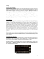
AT-200Pro
Automatic Antenna Tuner
Manual Version 1.0
LDG Electronics
1445 Parran Road, PO Box 48
St. Leonard MD 20685-2903 USA
Phone: 410-586-2177 Fax: 410586-8475 [email protected]
www.ldgelectronics.com
LDG AT-200Pro
Automatic Antenna Tuner
Introduction
Jumpstart, or “Real hams don’t read manuals!”
Specifications
4
3
4
An important word about power levels
Getting To Know Your AT-200Pro
Installation
Operation
4
5
7
8
Basic operation
Tuning
8
11
Auto and Semi-Auto Modes
12
Memory Tuning
12
Full Tuning Cycle (Long press)
12
Memory Tuning Cycle (Medium press)
13
Bypass mode (Short press)
13
Power and SWR Indication
14
Off Mode
14
Advanced Operation
14
Operation with an LDG radio interface:
Application Notes
15
17
Mobile operation
17
When to use Auto mode
17
When to use Peak mode
18
When to turn the LEDs off
18
RF Noise
18
MARS/CAP coverage
18
Error indications
Theory Of Operation
Some basic ideas about impedance
Transmitters, transmission lines, antennas and impedance
The LDG AT-200Pro
A word about tuning etiquette
Care and Maintenance
Technical Support
Warranty and Service
Firmware upgrades
Feedback
18
19
19
19
21
22
22
22
22
22
23
2
Introduction
Congratulations on selecting the LDG AT-200Pro tuner. The AT-200Pro provides fully
automatic, any mode antenna tuning across the entire HF range plus 6 meters at power levels to
250 watts. It will tune dipoles, verticals, Yagis or virtually any coax-fed antenna. It will match an
amazing range of antennas and impedances, far greater than some other tuners you may have
considered. Also, it consumes very little power making it suitable for battery-powered operations.
While resembling earlier LDG tuners in overall layout and function, the AT-200Pro represents a
quantum leap in features and performance. Enhanced tuning algorithms provide much faster,
precise and consistent tuning. Automatic tuning is now available during transmission, even SSB,
and many user-settable options are accessible from the front panel. The two large LED meters
provide simultaneous readings of power and SWR, and readouts of internal states and settings.
LDG pioneered the automatic, wide-range switched-L tuner in 1995. From its laboratories near
the nation’s capitol, LDG continues to define the state of the art in this field with innovative
automatic tuners and related products for every amateur need.
Jumpstart, or “Real hams don’t read manuals!”
Ok, but at least read this one section before you transmit:
1. Connect the antenna jack on your transceiver to the "Tx" jack on your AT-200Pro
tuner using a 50 Ohm coaxial cable jumper of appropriate power handling capability.
2. Connect your 50 Ohm antenna coax lead to the "Ant 1" jack on the back of your AT200Pro.
3. Connect your AT-200Pro to a source of 11 - 16 volts DC @ 750mA via the 2.5 by 5.5
mm power jack on the back (center positive).
4. Power up your transceiver and select the desired operating frequency.
5. Begin transmitting, any mode1.
6. Wait for the tuning cycle to end.
7. You’re now ready to operate.
1
If using SSB mode, simply speak into the microphone. You can tune while transmitting up to 125 watts if
your transceiver has a “roll-back circuit” to protect it from high SWR. If it does not have a roll-back circuit,
limit power when tuning to 25 watts to avoid damage to your transmitter or transceiver.
3
Specifications
•
0 to 250 watts SSB and CW peak power, 200 watts continuous (100 watts on 6M)
•
Easy to read LED bargraph display for RF power, SWR and status
•
16,000 "3-D" memories for instantaneous band changing
•
Two position antenna switch with memories for four antennas on each position
•
Tuning time: 0.5 to 6 seconds full tune, < 0.2 second memory tune
•
Built in frequency counter for memory operation
•
Frequency coverage: 1.8 to 54.0 MHz.
•
Tunes 6 to 1000 ohm loads (16 to 150 ohms on 6M), 6 to 4000 ohms with
optional 4:1 Balun (LDG RBA-1)
•
For Dipoles, Verticals, Vs, Beams or and Coax Fed Antenna
•
Optional external Balun allows tuning of random length, long wire or ladder line
fed antennas
•
Optional interfaces for Icom, Alinco, Kenwood and Yaesu available
•
Power requirements: 11 to 15 volts DC at 750 mA max during tuning
•
Enclosure: 9 x 7 x 2 inches
•
Weight: 2 pound
An important word about power levels
The AT-200Pro is rated at 250 watts maximum power input at most. Many ham transmitters and
transceivers, and virtually all amplifiers, output well over 250 watts. Power levels significantly
exceeding specifications will definitely damage or destroy your AT-200Pro. If your tuner fails
during overload, it could damage your transmitter or transceiver. Be sure to observe the specified
power limitations.
IMPORTANT SAFETY WARNING
Never install antennas over or near power lines. You can be
seriously injured or killed if any part of the antenna, support
or transmission line touches a power line. Always follow this
antenna safety rule: the distance to the nearest power line
should be at least twice the length of the longest antenna or
support dimension.
4
Getting To Know Your AT-200Pro
Your AT-200Pro is a quality, precision instrument that will give you many years of outstanding
service; take a few minutes to get to know it.
•
Your AT-200Pro can be used with any transceiver or transmitter with coax output operating
in the HF range at no more than 250 watts output. You can set the unit to tune automatically
whenever the SWR exceeds a set value, or you can set it to tune semi-automatically when you
start a tuning cycle by pressing the Tune button.
The front panel presents seven pushbutton controls, and two LED meters:
•
•
•
•
•
•
•
•
•
•
Power: turns the AT-200Pro on and off. When off, the tuner is in bypass. When turned on,
the tuner automatically resets to the last tuned setting
Tune: Initiates either a memory or full tuning cycle, and also places the tuner in "bypass"
mode.
Ant: Selects one of two antennas
C Up: Manually increase capacitance
C Dn: Manually decrease capacitance
L Up: Manually increase inductance
L Dn: Manually decrease capacitance
Func: Selects alternate functions for the other six buttons (see below)
PWR: LED meter indicates forward power in 25 and 250 watt ranges
SWR: LED meter indicates SWR while tuning or transmitting
After tuning, it automatically enters a “deep sleep” state in which it draws only about 10
milliamps. The tuner will automatically "wake up" the next time you start a tuning cycle, when
RF is present, a button is pushed or when an automatic cycle is needed. Tuning memories are
stored indefinitely in EEPROM memory.
The AT-200Pro has a total of 16,000 "3-D" frequency memories. There are 8,000 memories for
each of the two antenna ports, 2,000 tuning settings for each of four separate antennas. When you
transmit near a previously tuned frequency, you can use “Memory Tune” to reset the tuner in only
a fraction of a second. The process of storing tuning data in memory is completely automatic;
your AT-200Pro “learns” as you use it, adapting itself to all of the bands and frequencies you use.
5
On the back panel, there are six connectors:
•
•
•
•
•
•
RF input (marked “Tx”, standard SO-239 socket)
Antenna connector 1 (marked "Ant 1", standard SO-239 socket)
Antenna connector 2 (marked "Ant 2", standard SO-239 socket)
DC power in (2.5 by 5.5 mm power jack marked "Power", center positive)
Stereo 1/8” jack marked "Radio" for connecting a control cable to a compatible
transceiver
Ground connector (wing nut)
6
Installation
Your AT-200Pro tuner is intended for indoor use only; it is not water resistant. If you use it
outdoors (Field Day, for example) you must protect it from rain. The AT-200Pro is designed for
use with coax-fed antennas. If you wish to use it with longwires or antennas fed with a balanced
transmission line (e.g., ladder line), an external balun is required; either the LDG RBA-4:1 or
RBA-1:1 is ideal, depending on the antenna and transmission line used.
Always turn your radio off before plugging or unplugging anything. Your radio may be damaged if
you connect or disconnect a cable with the unit powered up. Note that some radios do not power
down the tuner even when the radio is turned off. To be safe, unplug the tuner's power connector
before plugging or unplugging anything else.
Connect the HF antenna jack on your transmitter or transceiver to the Tx jack on the back of your
AT-200Pro tuner using a coax jumper with standard PL-259 plugs (not provided). Properly
soldered connectors will be far more satisfactory and reliable than crimp-on or “solderless”
connectors. Attach your antenna lead-in coax to either the Ant 1 or Ant 2 jack on the back of your
AT-200Pro tuner. You will select the appropriate antenna from the front panel (see Operating
Instructions).
Your AT-200Pro can interface directly with many popular transceivers, enabling their “Tune”
button to start a tuning cycle, and in most cases providing power to the tuner. Optional cables and
interface adapters are available from LDG for many Alinco, Icom, Kenwood and Yaesu
transceivers. If you are using a transceiver interface, plug the adapter into the appropriate accessory
jack on the radio, and plug the stereo plug on the interface adapter cable into the Radio Interface
jack on the back of the tuner.
If you are not using an interface cable to a radio capable of powering the tuner, connect your AT200Pro to a source of DC power capable of providing 11 – 15 volts DC at 750 mA, using the
provided 2.5x5.5mm coaxial cable (center positive). If your radio is powered by 12 VDC, you can
use the same power supply for the AT-200Pro, providing the power supply can source the extra
750 mA required by the tuner during a tuning cycle.
Grounding your tuner will enhance its performance and safety. LDG recommends that you connect
your tuner to a suitable ground; a common ground rod connected to buried radials is preferred, but
a single ground rod, a cold water pipe or the screw that holds the cover on an AC outlet can
provide a serviceable ground. LDG strongly recommends that you use a properly installed, high
quality lightning arrestor on all antenna cables.
7
Operation
Basic operation
All functions are controlled through the seven front panel buttons. Each function is invoked when
the key is released. Some commands are indicated by the length of time you hold a button before
releasing it. There are three lengths of press: short (less than 0.5 seconds), medium (0.5 – 2.5
seconds) and long (more than 2.5 seconds). This sounds a lot more complicated than it actually is;
this interface will quickly become familiar and easy.
Setting Options
All settings are retained in EEPROM memory indefinitely, even if power is disconnected.
Separate settings are stored for each antenna, except for Antenna selection.
Startup Options
Your AT-200Pro has two startup commands, invoked by holding down one or more keys while
applying DC power to the unit (usually by plugging in the coaxial power connector).
Version display: Press and hold Func while powering up. This will display the version number
of the firmware in your tuner on the LED meters. The first digit of the version number is
displayed on the PWR meter, the second on the SWR meter. The LEDs use a one-of-eight
display, indicating 1, 2, 3, etc from right to left. In the example below, version 1.3 is displayed
(this is just an example; your version number may be different).
Version Display
All Reset: Press and hold Func+Ant+Tune while powering up. This will reset the unit to
factory defaults, and will erase all frequency memories.
8
Menu Options
Your AT-200Pro offers several options to adapt the tuner to your operations. Many functions are
controlled using the Func button. Press and release this button to place the tuner in Function
mode. You will see an "up arrow" display on the LED meters, indicating Function mode.
Function mode will time out after a few seconds, and a "down arrow" display will appear;
subsequent key presses must occur while function mode is still active. You can also cancel the
function mode by momentarily pressing the Func button a second time.
Function Mode On
Function Mode Off
The status check functions require you to press and hold the Func button. The following display
is shown during function hold:
Function Hold
9
Peak Mode On/Off: the LED wattmeter will read in average or peak watts. Average mode is most
suitable for 100% duty cycle modes like FM or RTTY. Peak mode is most suitable for modes in
which the amplitude varies, such as SSB or AM. The default is average mode.
To toggle between these two modes, press and release the Func button. Then press and release
the C Up button. You will see the highest power LED "float" behind the others, indicating peak
mode. Repeat this process to toggle back to Average mode, shown by the absence of the
"floating" LED.
Peak Mode
Wattmeter Scale: the LED wattmeter will indicate 25 or 250 watts maximum; the default is 250
watts. You will probably want to use the 12.5 watt scale when operating QRP to provide greater
resolution. To toggle between these two scales, press and release the Func button. Then press
and release the L Up button. The LED marked "20" or "250" will light momentarily to indicate
the 25 or 250 watt scale, respectively. The rightmost LED blinks at 30 or 300 watt over-range.
25 Watt Scale
250 Watt Scale
Automatic Tuning Mode: you can set your AT-200Pro to automatically begin a tuning cycle
whenever the SWR exceeds a value you set, or you can set it to semi-automatic, to tune only
when you begin a tuning cycle by pressing the Tune button. The default is Auto mode. To toggle
between Auto and Semi-auto modes, press and release the Func button. Then, press and release
the C Dn button. The LEDs will show the following patterns to indicate Auto and Semi mode:
Auto Mode
Semi Mode
10
Auto Tune Threshold: You can set the SWR at which an automatic tuning cycle will begin. press
and release the Func button. Then press and release the L Dn button. The SWR meter will show
the new setting. Repeat this sequence to cycle through the available values (1.1 - 3.5). The default
value is 2.0. The example below shows the threshold set to 1.7.
Auto Threshold Display
High/Low Impedance Toggle: You can manually set your AT-200Pro for Hi-Z or Lo-Z antennas.
Press and release the Func button. While this function is rarely used, it is available for the more
advanced user to temporarily set the tuner to an LC or CL configuration. To toggle the Hi/Lo-Z
setting, press and release the Ant button. The LEDs will show the following patterns to indicate
low and high impedance. This setting is relevant only when you are manually adjusting the match
using the C and L buttons. It is automatically set when you run any automatic tuning cycle.
Low Impedance
High Impedance
Antenna Selection: Press the Ant button to toggle between Ant 1 and Ant 2; the default is Ant 1.
The LED display points toward the selected antenna connector (as viewed from the front of the
unit). You cannot change antennas while transmitting; the antenna selection function is disabled
when RF is present. When you change antennas, the tuner references the last frequency used on
that antenna, and recalls tuning settings for that frequency, if any.
Antenna 1
Antenna 2
11
Tuning
Auto and Semi-Auto Modes
In Auto mode (see section on selection Auto or Semi mode) the tuner will begin a tuning cycle
whenever the SWR exceeds the value you set (see section on setting autotune threshold). In Semi
mode a tuning cycle begins only when you start one by pressing the Tune button, regardless of
SWR. You can also start a Semi tuning cycle while the tuner is in Auto mode. Your personal
operating practices will determine which mode is best for you. The default mode is Auto.
Auto mode tuning works well while you are transmitting in SSB, AM, CW or any digital mode.
Recent advances in LDG's tuning algorithms allow your AT-200Pro to tune effectively even with
a varying RF signal. This means that as you change frequencies, antennas or bands, you don't
have to make a separate tuning transmission; just start talking and your AT-200Pro will match up
in as little as 0.2 seconds.
Memory Tuning
This is pretty amazing, so lash yourself to the mast; your AT-200Pro has 16,000 3-D frequency
memories; 8,000 memories for each antenna port. They store the tuning parameters for each
frequency as you tune; that's 2,000 memories for each of four different antennas on each of the
two ports. You can use a wide variety of antennas, connecting them to the two antenna ports as
needed. Think of it; you could be using a Yagi, Quad, Loop or Vee on the Ant A port, and a
Dipole, Vertical, Longwire or J-Pole on the Ant B port, connecting them as needed (or switching
them through an external coax switch), and each of them will have 2,000 dedicated memories.
When you transmit on or near a memorized frequency again, the tuner finds the best match for
that port and antenna and resets those parameters in a fraction of a second, much faster than a full
tuning cycle. This will work best if you always use a particular antenna on the same antenna port
each time.
When you tune, you can select between a Memory tune and a Full tune. If you select Memory
tune and there is no appropriate memory data, the tuner will automatically begin a full tuning
cycle. Tuning parameters are stored in EEPROM memory, and are retained indefinitely, even if
power is removed.
Full Tuning Cycle (Long press)
Set your transmitter or transceiver to SSB, AM, FM, CW or Packet mode, and a power level of no
more than 125 watts if your radio has a power rollback circuit. If your radio lacks a rollback
circuit (see your owner’s manual), set the power level to no more than 25 watts.
Press the PTT switch on the microphone (close key on CW) to transmit a carrier, or simply begin
talking on SSB or AM. While transmitting, press and hold the Tune button on the front of your
AT-200Pro for at least 2.5 seconds.
Long Press > 2.5 Sec for Manual Tune
12
Release the Tune button; an automatic tuning cycle will begin. You will hear the relays in your
AT-200Pro as they switch in and out seeking a match; they make a buzzing noise. The tuning
cycle will end in a few seconds with the SWR LED meter indicating the final match. At the end
of a full tuning cycle, the SWR LEDs will scan inward from both ends to indicate a successful
tune to an SWR of less than 1.1.2
Unkey your transmitter or transceiver and reset to your desired power if you changed for tuning −
you’re ready to operate. The new tuning parameters are stored for the present operating
frequency, replacing any parameters that were previously stored for that frequency.
Memory Tuning Cycle (Medium press)
If you are tuning near a frequency at which you have already completed a tuning cycle, you can
reset the tuner very quickly by using a Memory Tuning Cycle. Key your transmitter as described
above, and press and hold the Tune button for .5 to 2.5 seconds, then release. The tuner will
automatically check for a saved tuning setting, and if present will restore that setting in a small
fraction of a second. If no tuned setting is saved near the present frequency, the tuner will begin a
full tuning cycle, saving the result when finished for future operation on that frequency. In this
way, your AT-200Pro “learns”; the longer you use it, the more closely it adapts itself to the bands
and frequencies you use. You will probably use Memory Tuning most of the time; it takes
advantage of any stored tuning settings, but automatically defaults to a Full Tuning cycle if no
stored data is available.
Memory frequency step size varies with band. Steps are very small on the 75 meter band to
accommodate the expected higher Q of most antennas, whereas the step size is somewhat larger
on 10 meters where antenna Q is usually lower.
Medium Press > .5 Sec for Auto Tune
Bypass mode (Short press)
To place your AT-200Pro in bypass mode, press the Tune button less than a half-second. The
tuner will switch to bypass. All LEDs will flash once to confirm bypass mode. In bypass mode
RF from your transmitter goes directly to the antenna with no matching. A second short press
toggles the tuner back to its last tuned setting; the LEDs show which C and L relays are
energized. Bypass followed by Func+Tune will clear the present memory. Bypass mode is not
saved when you power down. On the next power up, the tuner will reset the last tuned settings.
You can if you wish press Func-Tune to save the bypass setting, erasing the memory for that
frequency.
2
LDG's chief engineer, a fan of Snoopy in the Peanuts comic strip, calls this the "Happy Dance".
13
Power and SWR Indication
During a tuning cycle the Power and SWR LED meter indicate forward power and the present
SWR, respectively. If you are using a transmitter or transceiver with SWR rollback protection,
you will see the forward power vary up and down quite a bit during a tuning cycle. During
transmit, both forward power and SWR are displayed if this option is selected in the startup
options.
When no LEDs are lit on the SWR meter when RF is present, it means that the SWR is less than
1.1. When the LED segment labeled 1.1 is lit, it means that the SWR is between 1.1 and 1.3. The
1.3 LED indicates an SWR between 1.3 and 1.5, and so on. Read each LED segment to mean
"equal to or greater than the marked SWR, but less than the next higher marked SWR".
Off Mode
When any tuning cycle ends, the tuner automatically enters a “deep sleep” state in which it draws
about 10 milliamps. The tuner will automatically “wake up” the next time you start a tuning
cycle, when RF is present, a button is pressed or when an automatic tuning cycle is required, if
this option is selected. The tuner enters Bypass mode when you turn it off.
Advanced Operation
Manual adjustments
In rare cases, it may be desirable to manually adjust the match after a tuning cycle. This will
happen most often with antennas that are far from resonance at the operating frequency. The C
Up, C Dn, L Up and L Dn buttons increase and decrease capacitance and inductance,
respectively. Momentarily press any of these buttons to see the present setting; the value is
indicated on the display (C on the upper display, L on the lower), left-justified (that is, the lowest
order relay is shown on the left). To changes these values, press repeatedly or hold any of these
buttons; you will see the value change. Then, key your transmitter to observe the achieved SWR
on the SWR meter. You can also manually change C and L as you transmit, observing the SWR
on the meter; however, the C and L values are not displayed in this case. Frankly, you won't use
the manual adjustments very much; your AT-200Pro is very, very good at finding a match. These
functions are included only to provide you with the maximum utility and flexibility.
After manually adjusting the match, you can manually store the tuning parameters for the present
frequency; press the Func button, then the Tune button. The parameters are stored for later
recall, replacing any previously saved parameters for that frequency.
Status Query
You can query the status of most settings by pressing and holding the Func button while
pressing the relevant setting button. For example, to check the power scale of the PWR meter,
press and hold the Func key while pressing the L Up button. The PWR meter will indicate the
present scale setting without changing it. When done, release all buttons. Other status queries
include:
•
•
•
•
•
Ant: Presently selected antenna
C Up: Present PWR meter mode
C Dn: Present tune mode (Auto or Semi)
L Up: Present PWR meter scale
L Dn: Present Auto Tune threshold
14
Operation with an LDG radio interface:
Operation with an optional LDG radio interface is even simpler. With the interface installed on an
Alinco, Icom or Kenwood radio as noted, simply press the Tuner or AT button on the radio; for
Yaesu radios, press the Tune button on the tuner to begin an automatic tuning cycle. The radio
will automatically transmit a 10 watt carrier, and begin a AT-200Pro tuning cycle. Memory
settings will be used if available, otherwise a full tuning cycle will run. When the tuning cycle
ends, the radio will revert to its previous mode and power level.
Secondary Function Status Check (Func Power-Up
(Func + Button)
Hold + Button)
Function
Button
Primary Function
Tune
Manual Tune (Long)
Auto Tune (Medium)
Bypass (Short)
Manually Store Tuning
Parameters
Present Relay Settings
NA
Ant
Switch between Ant 1
and Ant 2 connectors
on back panel
Toggle Hi-Lo Impedance
Present Antenna
[Ant 1]
NA
C Up
Manually increase
capacitance
Toggle Power meter
Peak/Average
Present PWR Meter Mode
[Avg]
NA
C Dn
Manually decrease
capacitance
Set Auto/Manual Mode
Present Mode (Auto or
Semi)
[Auto]
NA
L Up
Manually increase
inductance
Set PWR Meter Scale
Present PWR Meter Scale
[125 Watts]
NA
L Dn
Manually decrease
inductance
Set Auto Tuning
Threshold SWR
Present Auto Tune
Threshold
[2.0]
NA
Func
Select Alternative
Functions For Other
Buttons
NA
NA
Version
Number
Func+
Ant+
Tune
NA
NA
NA
All
Reset
AT-200Pro Command Reference
15
Power
NA
NA
Version
Peak/Avg
Mtr Mode
NA
12/125 Watts
Mtr Scale
NA
Func
C Up
L Up
Hi/Lo Imp
Sel Ant
NA
Auto/Man
Tune Mode
NA
Auto Thresh.
Pres. Thresh.
NA
Ant
C Dn
L Dn
Man Store
Rly Settings
NA
Tune
Func + Key
Func Hold + Key
Hold on Power Up
Hold on power-up
for All Reset
AT-200Pro Key Reference
16
Application Notes
Mobile operation
The AT-200Pro is perfectly suited to mobile operation. You can install it under the dash along
with your transceiver, or remotely in the trunk. The only requirements are that the tuner remain
dry, and that you provide a fused source of DC power in accordance with the specifications. The
AT-200Pro does not include an internal fuse; you must provide one in the DC line. LDG
recommends a 2 Amp "fast blow" fuse. Make sure the tuner is well grounded to the car body.
To install the unit under the dash, you can "homebrew" a bracket. You can also use Velcro tape,
although the adhesive tends to soften in hot weather. In the trunk, Velcro works well to secure the
unit to the trunk floor. Simply run coax from your transceiver to the tuner, run a fused DC line to
the tuner and connect your mobile antenna. Simply set the tuner to Automatic mode, and you're
ready to go; the tuner will adjust the match as needed whenever you transmit on a new band or
frequency. You can observe the progress of the match on your rig's SWR meter, or on the power
output meter (not while driving; keep your eyes on the road!). When the reading stops changing,
the tuner has finished tuning. Most of the time this will happen very quickly, as the AT-200Pro
tunes from memory in less than a second.
Xcvr
Tuner
2A
DC
When to use Auto mode
Auto mode is most useful when you are often changing frequencies and bands (a contest, for
instance). With memory operation, Auto mode will retune almost instantly whenever you transmit
on a new frequency. On the other hand, if your antenna SWR is relatively flat across the band of
frequencies you're using, retuning might not be necessary, and semi-automatic mode would be
preferable.
17
When to use Peak mode
Any averaging wattmeter will read correctly only when excited by a steady, unmodulated carrier.
Any modulation will cause the reading to vary. Peak mode measures the peak power as the name
indicates, and is much steadier in the presence of modulated highs and lows. You will generally
want to use Peak mode when using SSB or AM, and average mode when using FM, RTTY or any
other 100% duty cycle mode that provides a steady carrier to the wattmeter circuitry.
When to turn the LEDs off
You can set the LEDs to remain off when transmitting. This will help conserve power when
operating from batteries (Field Day, for instance), or when you don't want the distraction of the
flashing LEDs.
RF Noise
The processor in your AT-200Pro creates a certain about of RF noise, which you may notice in
your receiver while tuning (only if you are using a separate receiver and not a transceiver) or
when information is being displayed in the LED display. This will be most noticeable when
operating CW with break-in, while using the Peak power display. This should present no
problem, as the Peak mode is not very useful on CW. The extremely short tuning cycle
minimizes the impact of the noise; the tuner creates no RF noise while not tuning.
MARS/CAP coverage
Your AT-200Pro provides tuning continuously over its specified range, not just in the ham bands.
This makes it useful for MARS or CAP operation, or any other legal HF operation.
Error indications
There are four error states that are indicated on the Power LED display by all LEDs flashing
twice:
1. No RF is present when a tune command is executed. So, if you press and hold Tune for a full
tuning cycle, but no RF is present, the LEDs will flash.
2. RF removed during a tune. If you stop transmitting during a tuning cycle, the LEDs will
flash.
3. Full tune below Auto tune threshold. If you start a full tuning cycle when the SWR is already
below the Auto tune threshold, the LEDs will flash.
4. Reading over-range.
To correct error conditions 1 or 2, simply provide RF for the duration of the tuning cycle. Error
condition 3 indicates that a tune cycle is not needed. Error condition 4 indicates power or SWR
beyond the range of the meters.
18
Theory Of Operation
Some basic ideas about impedance
The theory underlying antennas and transmission lines is fairly complex, and in fact employs a
mathematical notation called “complex numbers” that have “real” and “imaginary” parts. It is
beyond the scope of this manual to present a tutorial on this subject3, but a little background will
help you understand what your AT-200Pro is doing, and how it does it.
In simple DC circuits, the wire resists the current flow, converting some of it into heat. The
relationship between voltage, current and resistance is described by the elegant and well-known
“Ohm’s Law”, named for Georg Simon Ohm of Germany, who first discovered it in 1826. In RF
circuits, an analogous but far more complicated relationship exists.
RF circuits also resist the flow of electricity. However, the presence of capacitive and inductive
elements causes the voltage in the circuit to lead or lag the current, respectively. In RF circuits
this resistance to the flow of electricity is called “impedance”, and can include all three elements:
resistive, capacitive, and inductive.
Capacitive
Reactance
Inductive
Reactance
The output circuit of your transmitter consists of inductors and capacitors, usually in a
series/parallel configuration called a “pi network”. The transmission line can be thought of as a
long string of capacitors and inductors in series/parallel, and the antenna is a kind of resonant
circuit. At any given RF frequency, each of these can exhibit resistance, and impedance in the
form of capacitive or inductive “reactance”.
Transmitters, transmission lines, antennas and impedance
The output circuit of your transmitter, the transmission line, and the antenna all have a
characteristic impedance. For reasons too complicated to go into here, the standard impedance is
about 50 ohms resistive, with zero capacitive and inductive components. When all three parts of
the system have the same impedance, the system is said to be “matched”, and maximum transfer
of power from the transmitter to the antenna occurs. While the transmitter output circuit and
transmission line are of fixed, carefully designed impedance, the antenna presents a 50 ohm, nonreactive load only at its natural resonant frequencies. At other frequencies, it will exhibit
capacitive or inductive reactance, causing it to have an impedance different from 50 ohms.
When the impedance of the antenna is different from that of the transmitter and transmission line,
a “mismatch” is said to exist. In this case, some of the RF energy from the transmitter is reflected
from the antenna back down the transmission line, and into the transmitter. If this reflected
energy is strong enough it can damage the transmitter’s output circuits.
The ratio of transmitted to reflected energy is called the “standing wave ratio”, or SWR. An SWR
of 1 (sometimes written 1:1) indicates a perfect match. As more energy is reflected, the SWR
3
For a very complete treatment of this subject, see any edition of the ARRL Handbook for Radio
Communications (previously the Handbook For Radio Amateurs)
19
rises to 2, 3 or higher. As a general rule, modern solid state transmitters must operate with an
SWR of 2 or less. Tube exciters are somewhat more tolerant of high SWR. If your 50 ohm
antenna is resonant at your operating frequency, it will show an SWR close to 1. However, this is
usually not the case; operators often need to transmit at frequencies other than resonance,
resulting in a reactive antenna and a higher SWR.
SWR =
1+ R / F
1− R / F
where F = Forward power (watts), R = Reflected power (watts)
SWR is measured using a device called an “SWR bridge”, inserted in the transmission line
between the transmitter and antenna. This circuit measures forward and reverse power from
which SWR may be calculated (some meters calculate SWR for you). More advanced units can
measure forward and reverse power simultaneously, and show these values and SWR at the same
time.
An antenna tuner is a device used to cancel out the effects of antenna reactance. Tuners add
capacitance to cancel out inductive reactance in the antenna, and vice versa. Simple tuners use
variable capacitors and inductors; the operator adjusts them by hand while observing reflected
power on the SWR meter until a minimum SWR is reached. Your LDG AT-200Pro automates
this process.
Reflected Power (Watts)
No tuner will fix a bad antenna. If your antenna is far from resonance, the inefficiencies inherent
in such operation are inescapable; it’s simple physics. Much of your transmitted power may be
dissipated in the tuner as heat, never reaching the antenna at all. A tuner simply “fools” your
transmitter into behaving as though the antenna were resonant, avoiding any damage that might
otherwise be caused by high reflected power. Your antenna should always be as close to
resonance as practical.
2
4
6
8
10
12
14
16
18
20
22
24
26
28
30
32
34
36
38
40
42
44
46
48
50
Forward Power (Watts)
20
30
40
1.92
1.70
1.58
2.62
2.15
1.92
3.42
2.62
2.26
4.44
3.14
2.62
5.83
3.73
3.00
7.87
4.44
3.42
11.24
5.31
3.90
17.94
6.42
4.44
37.97
7.87
5.08
9.90
5.83
12.92
6.74
17.94
7.87
27.96
9.32
57.98
11.24
13.93
17.94
24.63
37.97
77.99
-
50
1.50
1.79
2.06
2.33
2.62
2.92
3.25
3.60
4.00
4.44
4.94
5.51
6.17
6.95
7.87
9.00
10.40
12.20
14.60
17.94
22.96
31.30
47.98
97.99
-
60
1.45
1.70
1.92
2.15
2.38
2.62
2.87
3.14
3.42
3.73
4.07
4.44
4.85
5.31
5.83
6.42
7.09
7.87
8.80
9.90
11.24
12.92
15.08
17.94
21.95
70
1.41
1.63
1.83
2.02
2.22
2.41
2.62
2.83
3.06
3.30
3.55
3.83
4.12
4.44
4.79
5.18
5.60
6.07
6.60
7.19
7.87
8.65
9.56
10.63
11.92
80
1.38
1.58
1.75
1.92
2.09
2.26
2.44
2.62
2.80
3.00
3.21
3.42
3.65
3.90
4.16
4.44
4.75
5.08
5.44
5.83
6.26
6.74
7.27
7.87
8.55
90
1.35
1.53
1.70
1.85
2.00
2.15
2.30
2.46
2.62
2.78
2.96
3.14
3.32
3.52
3.73
3.95
4.19
4.44
4.71
5.00
5.31
5.65
6.02
6.42
6.85
100
1.33
1.50
1.65
1.79
1.92
2.06
2.20
2.33
2.47
2.62
2.77
2.92
3.08
3.25
3.42
3.60
3.80
4.00
4.21
4.44
4.68
4.94
5.22
5.51
5.83
SWR Lookup Table
Find SWR at intersection of
forward power column and
reflected power row.
20
The LDG AT-200Pro
In 1995 LDG pioneered a new type of automatic antenna tuner. The LDG design uses banks of
fixed capacitors and inductors, switched in and out of the circuit by relays under microprocessor
control. A built-in SWR sensor provides feedback; the microprocessor searches the capacitor and
inductor banks, seeking the lowest possible SWR. The tuner is a “Switched L” network consisting
of series inductors and parallel capacitors. LDG chose the L network for its minimum number of
parts and its ability to tune unbalanced loads, such as coax-fed dipoles, verticals, Yagis; in fact,
virtually any coax-fed antenna. The inductors are switched in and out of the circuit by relays
controlled by the microprocessor. An additional relay switches between high and low impedance
ranges.
The capacitors are connected to ground with the seven inductor relays. Another relay switches the
entire capacitor bank to the input or output side of the inductor. This switching allows the AT200Pro to automatically handle loads that are greater than 50 ohms (high setting) and less than 50
(low setting). All of the relays are sized to handle over 300 watts continuously.
The SWR sensor is a variation of the Bruene circuit. This SWR measuring technique is used in
most dual-meter and direct-reading SWR meters. Slight modifications were made to the circuit to
provide voltages (instead of currents) for the analog-to-digital converters (ADCs) that provide
signals proportional to the forward and reverse power levels. The single-lead primary through the
center of the sensor transformer provides RF current sampling. Diodes rectify the sample and
provide a dc voltage proportional to RF power. Variable resistors calibrate the FORWARD and
REVERSE power levels. Once adjusted, the forward and reverse power sensors produce a
calibrated DC voltage proportional to the forward and reverse RF power levels. These two
voltages are read by the ADCs in the microprocessor. Once in a digital format, the they are used
to calculate SWR in real time.
The relays operate from DC supplied by via the power input jack. The total current drawn by the
AT-200Pro depends primarily on the number of energized relays, with the maximum current
drain being approximately 750 mA, but only during the few seconds a tuning cycle is running. At
all other times, the tuner is in a “deep sleep” mode drawing only a few milliamps. The last tuned
setting is automatically reset on the next power-up.
Although the microprocessor’s oscillator runs at 20 MHz. The main tuning routine takes about 75
cycles to make a tuner adjustment and take a new SWR measurement, or 7 milliseconds per tuner
adjustment. If running at maximum speed, the microprocessor can try all inductor-capacitor
combinations in under 3 seconds. Unfortunately, the mechanical relays can’t react as quickly as
the microprocessor, and the tuning speed must be slowed down to compensate for relay settling
time.
The tuning routine, written in assembly language, uses an algorithm to minimize the number of
tuner adjustments. The routine first de-energizes the high/low impedance relay if necessary, then
individually steps through the inductors to find a coarse match. With the best inductor selected,
the tuner then steps through the individual capacitors to find the best coarse match. If no match is
found, the routine repeats the coarse tuning with the high/low impedance relay energized. The
routine then fine tunes the capacitors and inductors. The program checks LC combination to see if
a 1.5 or lower SWR can be obtained, and stops when it finds a good match.
The microprocessor runs a fine tune routine just after the tuner finds a match at an SWR of 1.5 or
less. This routine tries to get the SWR as low as possible (not just 1.5); it takes about a half
21
second to run. There is also a quick tune mode. If the swr is below 2.0 when you press the tune
button to start a tuning cycle, the tuner will first try a memory tune routine to see if it can achieve
a low swr without a complete re-tune. This also takes about a half second to run. If it does not
find a good match, then it runs a full tuning routine.
A word about tuning etiquette
Be sure to use a vacant frequency to tune. With today’s crowded ham bands, this is often difficult.
However, do your best to avoid interfering with other hams as you tune. Your AT-200Pro’s very
short tuning cycle, as little as a fraction of a second, minimizes the impact of your tuning
transmissions.
Care and Maintenance
Your AT-200Pro tuner is essentially maintenance-free; just be sure to observe the power limits
discussed in this manual. The outer case may be cleaned as needed with a soft cloth slightly
dampened in household cleaning solution. As with any modern electronic device, your AT200Pro can be damaged by temperature extremes, water, impact or static discharge. LDG strongly
recommends that you use a good quality, properly installed lightning arrestor in the antenna lead.
Technical Support
We are happy to help you with your AT-200Pro. Telephone technical support is available at 410586-2177 weekdays from 9 am to 5pm Eastern Time. Inquiries by Fax at 410-586-8475 are
welcome, and prompt e-mail support is available at [email protected].
Warranty and Service
Your AT-200Pro is warranted against defects in parts or workmanship for two years from
purchase. The warranty does not cover damage due to abuse or exceeding specifications. This
warranty applies to the original purchaser only; it is not transferable. A copy of the receipt
showing the purchaser’s name and the date of purchase must accompany units returned for
warranty service. All returns must be shipped to us pre-paid; we will not accept units with
postage due. A return form is provided on our web site for your convenience.
If you need to return your AT-200Pro to us for service, package it carefully, keeping in mind that
we will re-use your packaging to return the unit to you. Download the return form from our web
site, fill it out and return it with your tuner. A self-addressed return-shipping label, while not
required, will help insure speedy and accurate delivery of your repaired unit. Include a full
description of the problem, along with your name, address and a phone number or e-mail address
where we can reach you with any questions. Repairs average about 3 to 6 weeks.
We will be glad to service your AT-200Pro after the warranty period has ended. We will notify
you of repair charges by phone or e-mail, and bill you after repairs are completed.
Firmware upgrades
From time to time LDG may release upgraded firmware for the AT-200Pro, refining operation
and adding features. Your AT-200Pro is not field programmable; you will have to remove the
present chip and replace it with the upgrade chip. You will return the old processor chip to LDG;
upgrades will be sold by exchange only. The processor chips are recycled and reprogrammed to
22
minimize future upgrade costs. Upgrades are expected to cost about $10-$20 with chip exchange,
and will be announced on our web site when available.
Feedback
If you have an idea to improve our software or hardware, please send us a description. If we
incorporate your idea in the AT-200Pro, we'll send you a free upgrade as a “thank you”.
We encourage everyone who uses the AT-200Pro to contact us (card, letter or e-mail preferred)
telling us how well it works for you. We are also always looking for photographs of our products
in use; we frequently place such pictures on our Web site (www.ldgelectronics.com).
23