1
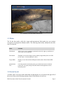
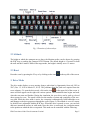
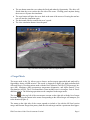
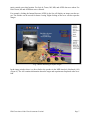
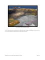
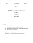
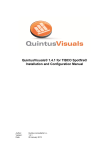
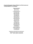
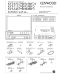
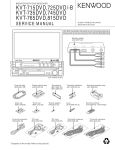
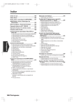
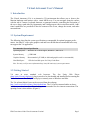
Virtual Astronaut User’s Manual 1. Introduction The Virtual Astronaut (VA) is an interactive 3D environment that allows you to observe the Martian landscape and interact with a virtual MER rover. You can navigate along the surface with the aid of a mouse, keyboard shortcuts, or gamepad controls, controlling the navigation of the rover along a path taken by Opportunity and visiting targets with in-situ observations. Additional capabilities are provided to alter the contrast of the scene, change the terrain, and make measurements. 1.1 System Requirement The following chart lists the system specifications recommended for optimal program performance. An older PC with a poor graphics card and lower RAM than recommended below may not support the VA application. Recommended System Specification Operating System Windows XP 32 bit or higher, Windows 7, Mac OS X System Memory ≥2 GB RAM Graphics Memory Recommended ≥512 MB (A dedicated graphics card is recommended) Hard Disk Space 1 GB free hard disk space for Unity-Cache-Data Note: See unity web for more information http://unity3d.com/unity/system-requirements. 1.2 Getting Started VA runs in most standard web browsers. The free Unity Web Player (http://unity3d.com/webplayer/) plug-in needs to be downloaded and installed before running the Virtual Astronaut. The Unity 3D web player currently runs on Windows and Mac. The VA at Santa Maria Crater can be accessed from the webpage http://wufs.wustl.edu/kvt/Santa_Maria/default.htm. The VA can be streamed online or downloaded to your local machine. Downloading is recommended for slow internet connections. The opening screen is shown below (Figure 1). PDS Geosciences Node Virtual Astronaut Version 1 Page 1 Fig. 1 Opening scene with toolbar at the top left. 1.3 Modes The VA has four modes: walk, drive, target, and measurement. Each mode gives you a unique viewpoint to investigate the Martian surface. The following chart briefly summarizes the function of each mode. Mode Function Walk Mode Allows you to move around the terrain and to look left, right, up, and down as if he or she were an astronaut. Drive Mode Simulates a rover drive along a traverse taken by Opportunity from sols 2450 to 2547 (Dec. 15, 2010 to March 25, 2011). Target Mode Displays in-situ observations with high-resolution data collected from MER rovers. Measurement Tool Gives the position of measured points, gives the distance from a measured point to the view point, and provides the distance and height between two measured points. 1.4 Screen layout A toolbar with 7 icons and a slider underneath for adjusting the size is located in the upper left of the screen. Refer to the following summary chart for the function of each icon. PDS Geosciences Node Virtual Astronaut Version 1 Page 2 Name Function Drive Mode Opens the rover simulation menu with buttons to run, reset, and close. The slide bar controls the speed of the simulation. Target Mode Launches a menu containing a list of targets approached and analyzed by Opportunity. Selecting a target will transport the astronaut to the target location. Measurement Tool Activates the measurement tool that allows you to measure the dimensions of a target. Terrain Tool Opens a menu to adjust the terrain vertical exaggeration factor and control the visibility of different layers in the scene. Help Tool Directs you to the webpage with VA user’s scenario and user’s manual. Contrast Tool Adjusts the contrast/brightness of a scene. Reset Tool Resets the scene to the initial positioning. 2. Walk Mode The walk mode allows you to explore and view the Martian landscape to better understand and visualize the geomorphic and geologic contexts. 2.1 Navigation The VA supports navigation with a mouse, keyboard shortcuts, or a gamepad. Simulate walking forward or backward through the scene by clicking the top or bottom of the screen (or by using E/D). Rotate the astronaut left or right by selecting a point in the left or right of the screen. To move left or right without rotation, hold down Ctrl while clicking in the corresponding side of the screen (Figure 2). The navigation speed is determined by the distance between the center of the screen and the cursor. Clicking on a point near the center of the screen, which is the intersection of two black lines on the screen, will result in little to no movement. Conversely, the farther away you click a point from the center, the faster the navigation. Moving the mouse along the vertical black line on the screen will result in the forward or backward movement. Moving along the horizontal black line on the screen will result in rotate operation. PDS Geosciences Node Virtual Astronaut Version 1 Page 3 Fig. 2 The left image shows the direction of movement using the mouse in walk mode. The right image displays the direction of movement while holding Ctrl. The astronaut’s viewpoint can be changed by using a combination of the keyboard and mouse. You can look around by holding 'Shift' while clicking and dragging the cursor in the direction you wish to look. A summary of the navigation controls can be found in the table below and figure 3. Note that using the gamepad allows for more than one control to be used at a time. Quick Navigation Guide Functions Keyboard Mouse Gamepad Move forward/backward E/D Drag (or click and hold) in top/bottom of screen Left joystick push up /down Move left/right S/F 'Ctrl' key and drag cursor in left/right of screen Left joystick push to the left/right Change altitude R/W N/A LT/RT Button Turn left/right (Yaw) J/L Drag to the left/right Right joystick push to the left/right Look up/down (Pitch) I/K 'Shift' key and drag cursor in top/bottom of screen Right joystick push up /down Reset Y N/A X Button Increase Speed X for translation and B for rotation Drag farther away from center Y Button Decrease Speed V for translation and M for rotation Drag towards the center B Button PDS Geosciences Node Virtual Astronaut Version 1 Page 4 Fig. 3 Functions of shortcut keys. 2.2 Altitude The height at which the astronaut moves above the Martian surface can be chosen by pressing the R/W keys or pushing the Gamepad LT/RT Button. The default height is 4.5 meters for both the walk and drive modes. While in the target mode, the height is initially set at 1.5 meters. 2.3 Reset Reset the scene by pressing the Y key or by clicking on the icon in the top left of the screen. 3. Drive Mode The drive mode displays a rover moving along a path taken by Opportunity from sols 2450 to 2547 (Dec. 15, 2010 to March 25, 2011). The positions along the path were acquired from the rover telemetry. To open the drive mode, click on the icon in the upper left of the screen. A menu will then appear on the right with various options. The simulation timer begins and ends when the run starts and finishes. During the simulation, the rover drive can be sped up, slowed down, paused or reset. The speed is based on the number of points and complexity of the traverse path. While the drive mode is active, the viewpoint is automatically fixed behind the rover and changes as the drive progresses through the scene (Figure 4). The altitude is set at 4.5 meters by default, but is adjustable with the R/W keys. When the drive is paused or reset, you can look and move around the surface in walk mode. Once the drive is reactivated, the viewpoint returns to the position at which the drive was paused. This mode can be controlled with the following: PDS Geosciences Node Virtual Astronaut Version 1 Page 5 The run button starts the rover along the fixed path taken by Opportunity. The drive will finish when the rover reaches the east side of the scene. Clicking pause anytime during the traverse will pause the simulation. The reset button will place the rover back at the start of the traverse. Pressing the run button will start the simulation again. The horizontal slide bar controls the rover’s speed. The close simulation button closes the panel. Fig. 4 A rover driving a path taken by Opportunity. 4. Target Mode The target mode in the VA allows you to observe surface targets approached and analyzed by Opportunity during a MER mission. This mode is designed to display the high-resolution data collected from in-situ observations made with the Rock Abrasion Tool (RAT), Microscopic Imager (MI), Mössbauer (MB) spectrometer temperature diagnostics, and Alpha Particle X-ray Spectrometer (APXS). The VA at Santa Maria Crater includes two in-situ targets: Luis de Torres and Ruiz Garcia. The following operations can be completed in the target mode: The icon in the top left of the screen opens a menu on the right side with the list of target locations. Selecting the button in the menu corresponding to the desired target will transport you to the location (Figure 5). The menu on the right side of the screen expands to include a list with the MI focal section merge and Hazcam images that portray both the selected target and the experiments that OpporPDS Geosciences Node Virtual Astronaut Version 1 Page 6 tunity carried out at that location. For Luis de Torres, MI, MB, and APXS data were taken. For Ruiz Garcia, MI and APXS data were collected. For example, clicking the button Hazcam (APXS) in the list will display an image near the target. The window can be moved for better viewing. Right clicking on the rover can also open the images. Fig. 5 Rover observing a surface target. In the image window there is a direct link to the product in the MER Analyst's Notebook (AN) (Figure 6). The AN contains information about the target and experiments completed at the location. PDS Geosciences Node Virtual Astronaut Version 1 Page 7 Fig. 6 Rover observations archived in the PDS Analyst’s Notebook. 5. Measurement Tool The measurement tool can be opened by clicking on the icon This tool can: in the top left of the screen. Give the position of measured points, Give the distance from a measured point to the view point, and Provide the distance and height between two measured points. There are two ways to use the measurement tool depending on how the cursor is used. A single left click on the screen returns the position of a point and its distance to the view point. Another way to use this mode is to determine the distance and height between two points. Left clicking on the first point and then dragging to a second point will bring up a window near the cursor with the distance and height measurements (Figure 7). To close the measurement tool, click on the icon in the upper left of the screen again. PDS Geosciences Node Virtual Astronaut Version 1 Page 8 Fig. 7 An astronaut making a measurement. 6. Scene Adjustments You can adjust scene contrast and the visibility of the mosaic layers forming the scene. Both of these adjustments can be accessed from the toolbar in the top left of the screen. 6.1 Scene Contrast The contrast of the scene can be adjusted in order to highlight targets on the surface. Dragging the horizontal slider above the icon in the upper left of the screen will increase or decrease the contrast of the scene. Clicking the sun icon under the slider will reset the scene to the default contrast setting. 6.2 Surface Layers The 3D terrain in the VA includes multiple surface overlays on a digital elevation model. In order to alter the surface, click on the icon in the upper left of the screen. The layers are made up of image mosaics at various resolutions and an orbital HiRISE image. The surface areas covered by the mosaics include Luis de Torres, Ruiz Garcia, and the southeast crater. Visibility of the layers can be controlled by switching between turn on and turn off in the menu on the right side. The vertical exaggeration can also be multiplied or divided by two by clicking the button *2 or /2, respectively (Figure 8). If you observe an empty scene after the process, press the reset button in the upper left of the screen to reset the scene. PDS Geosciences Node Virtual Astronaut Version 1 Page 9 Fig.8 Surface layer adjustment menu. The Virtual Astronaut is produced by the PDS Geosciences Node at Washington University in St. Louis. Send comments and questions to [email protected]. PDS Geosciences Node Virtual Astronaut Version 1 Page 10